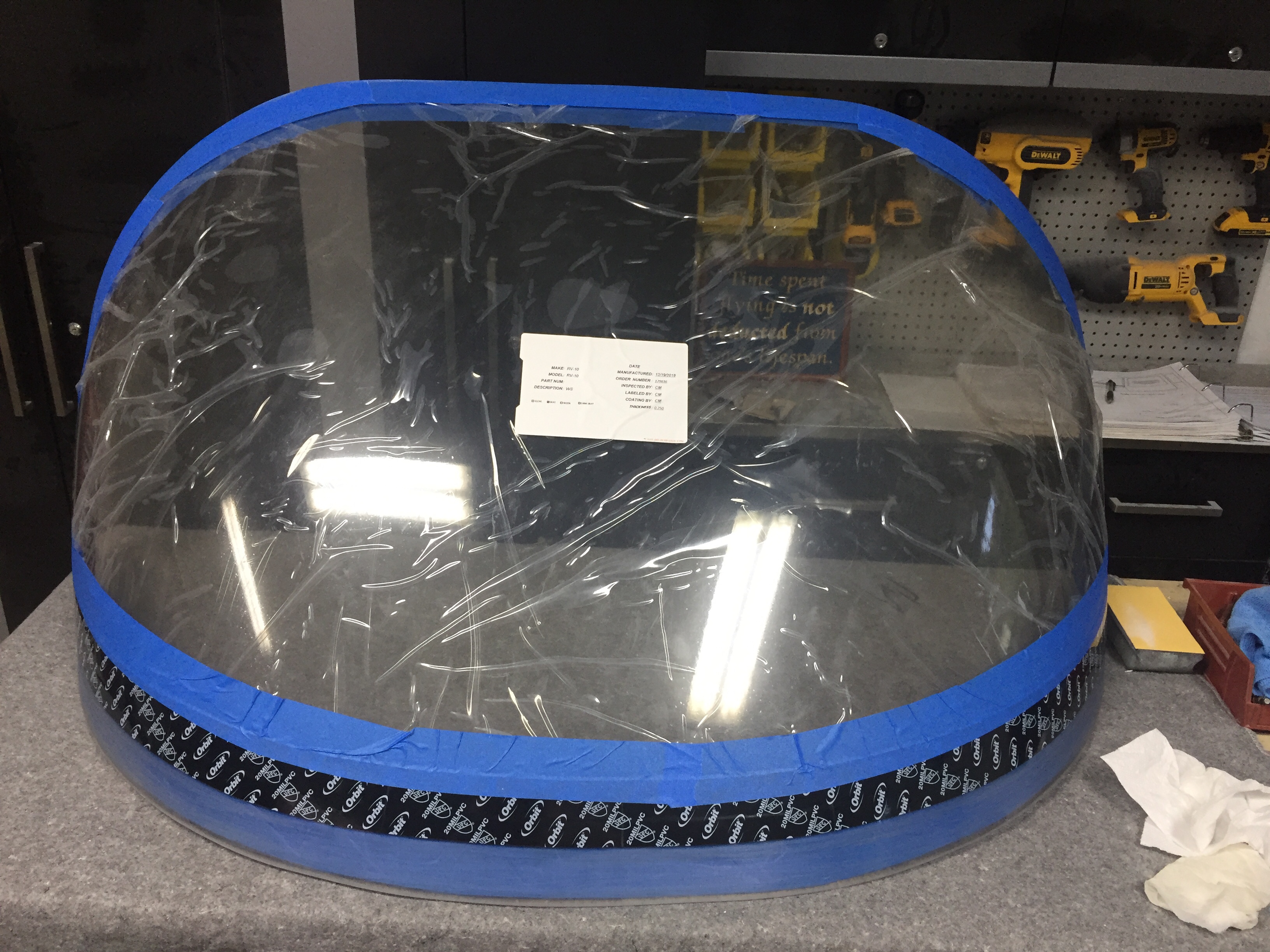
I continue to empty my parts inventory which is nice to give the space back to what it should be such as guest bedroom and bonus room upstairs. A big chunk of floor space has been taken up by the windscreen. Now, the story is I received my order from Cee Baileys many months ago but the box was damaged and the thoughtful FedEx driver decided to take the bundled plexi out of the damaged box and simply lay on the diamond plate steel floor before continuing the route. Needless to say, my brand new windscreen was no longer brand new. It’s not to say that it’s ruined, it just didn’t meet my standards. I was lucky to only have a few tiny nicks that won’t even show up on a camera picture, but are visible if you look hard enough. A claim and call back to Cee Baileys had a replacement in a better box on the way to me. I plan to sell the original one at a good discount and it may work for someone building on a budget or as a repair, who knows. Either way, my fuselage was ready for a windscreen.
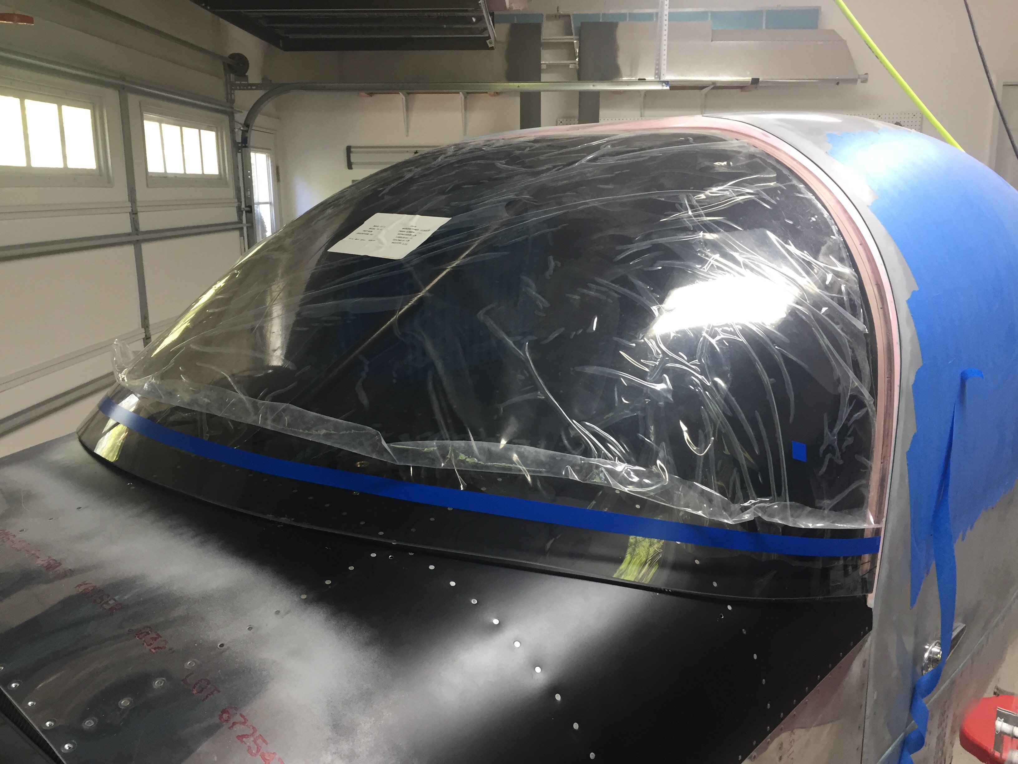
I prepped it just as I did on the windows and since I had already rough trimmed it, I was able to get the final fitment completed in just one evening. I’ll be using a mix of methods to install it, following the plans on the lower edge and using the Sikaflex method around the cabin top. I again traced the edge of the cabin top onto the plexi so I could tape it using the sportsman method. It was actually easier since I only had half the area needing taped.
I also ground down the two side corners of the plexi to allow a nice flat surface once the fiberglass layup is applied. I’ve seen and heard others having a buldge on either side of the fuselage and most women find buldges unsightly and moderately annoying. This is all about impressing the ladies, so no buldges on Tess! I decided to apply the Sika primer on the outside of the bottom area to help hide the fiberglass overlay. I also have black die for the epoxy. Once the skin was roughed up, I laid a good bead of Sikaflex down and Laura helped me set the screen in place.
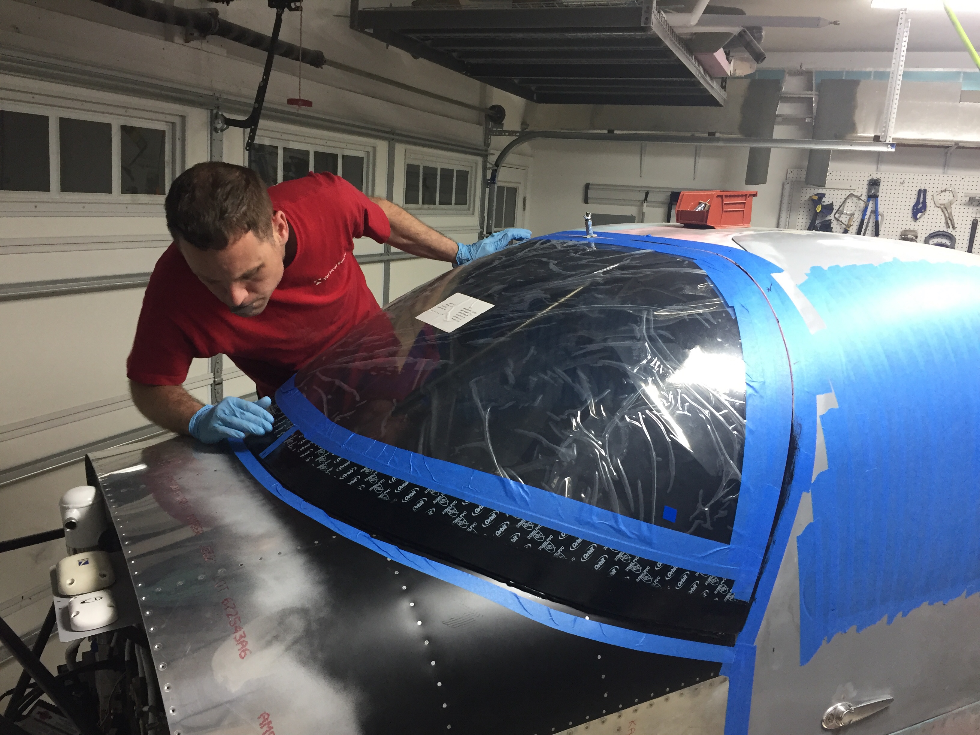
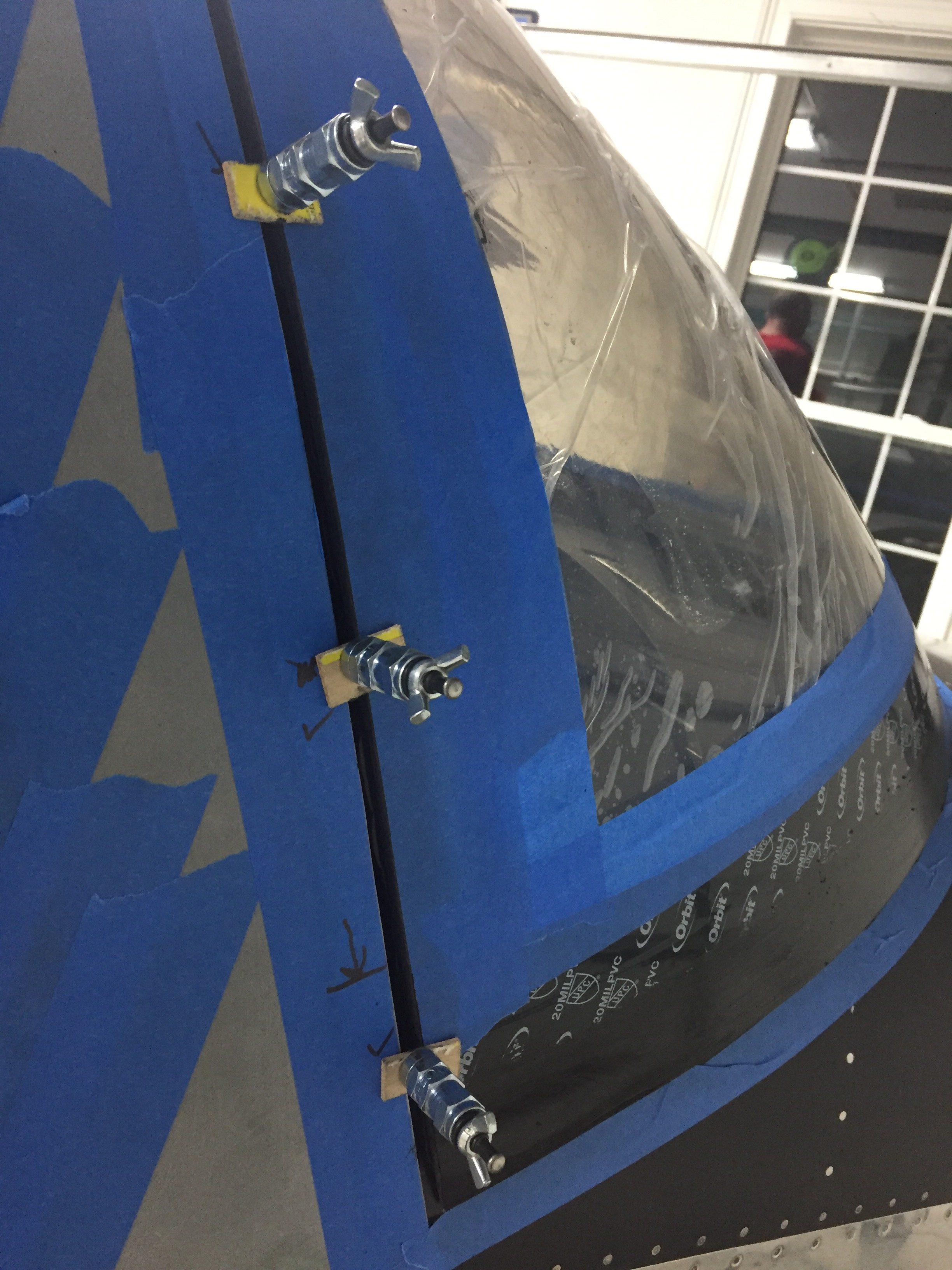
I worked quickly again to put the wing nut clecos in and level out the screen to the cabin top. It went well and soon enough it was time to clean up the inside. Again, time spent prepping the tape proved to be priceless, as the inside of the screen came out perfect and professional looking. I didn’t have any sealant on the plexi at all nor did any get on the cabin interior paint. All in all, I’m really pleased with it. Once the Sika cures, I’ll start on the fiberglass fairing at the bottom. Again, the Sika will fill in the gap around the rest of the windscreen after paint is completed.
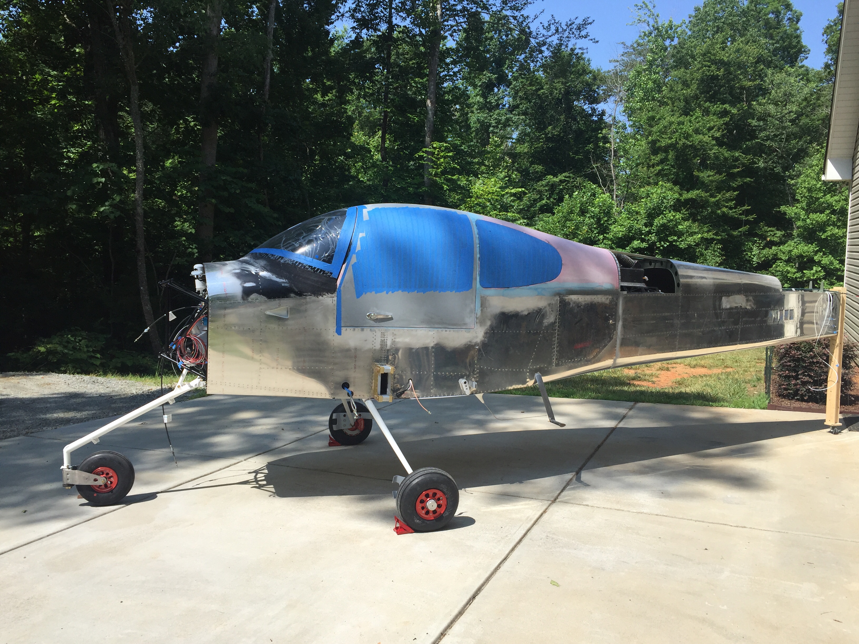
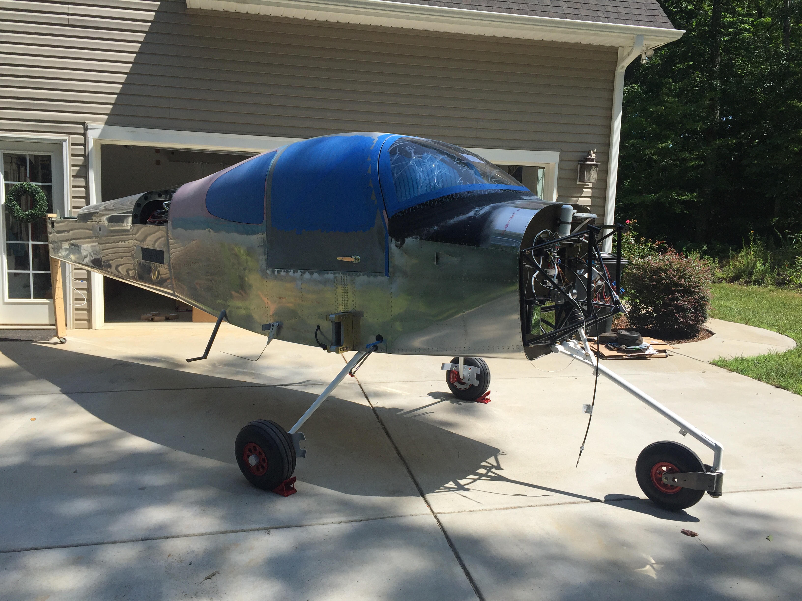
The next project and main goal before the engine arrives this summer is to get her up on the landing gear. I bought a fancy Harbor Freight engine hoist to assist in the task and after some usualy frustration at assembling a HF tool, it was ready to roll. I had a friend who’s building a Glasair come over and help with the lifting of the fuselage. It was nice to have a extra set of hands besides Laura’s and my own. He hooked up the chains on the engine mount as I padded a workbench and got the components ready. The lift was really a non-event but nerve wracking none the less to see the fuselage hanging in mid air!
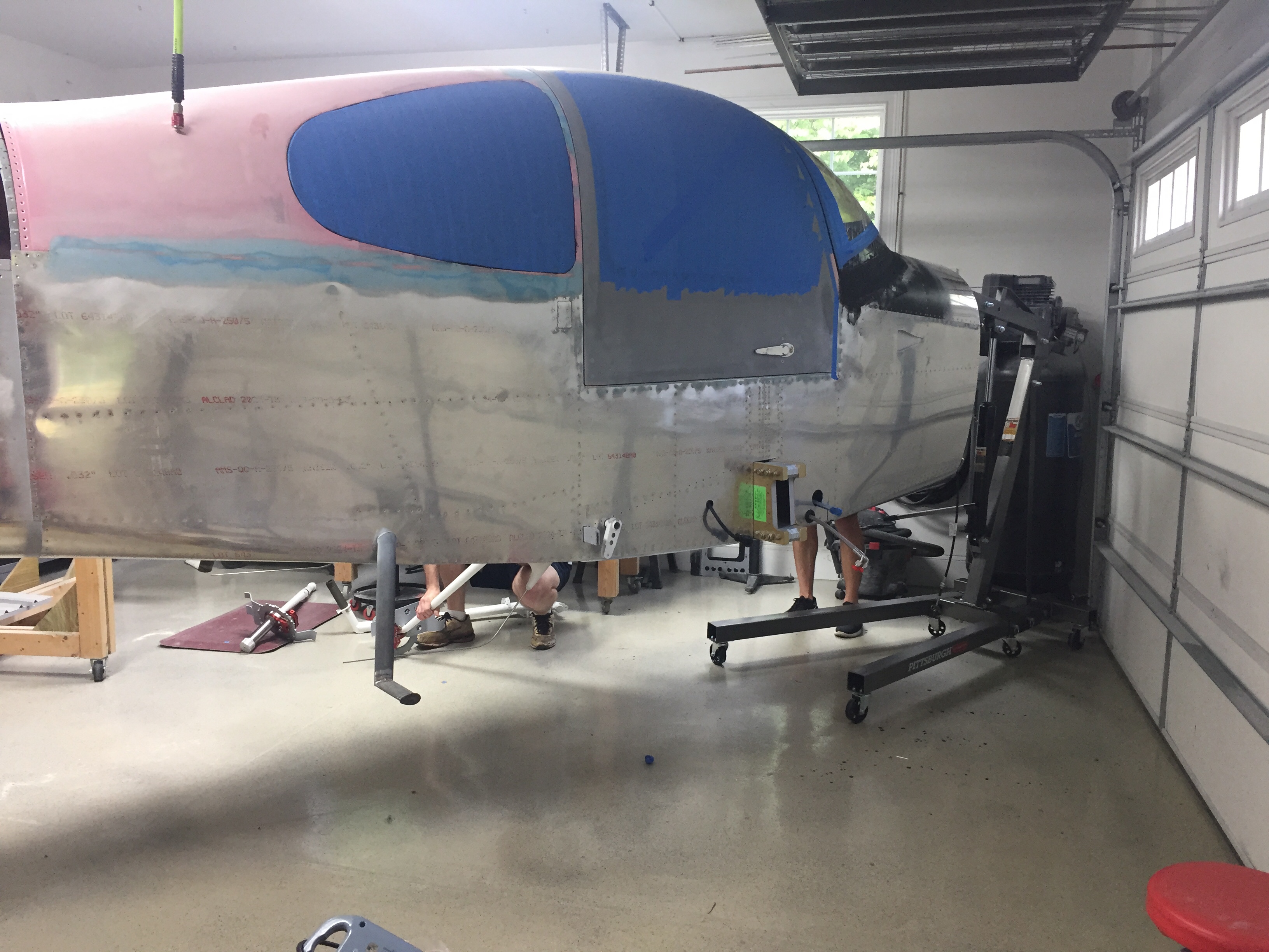
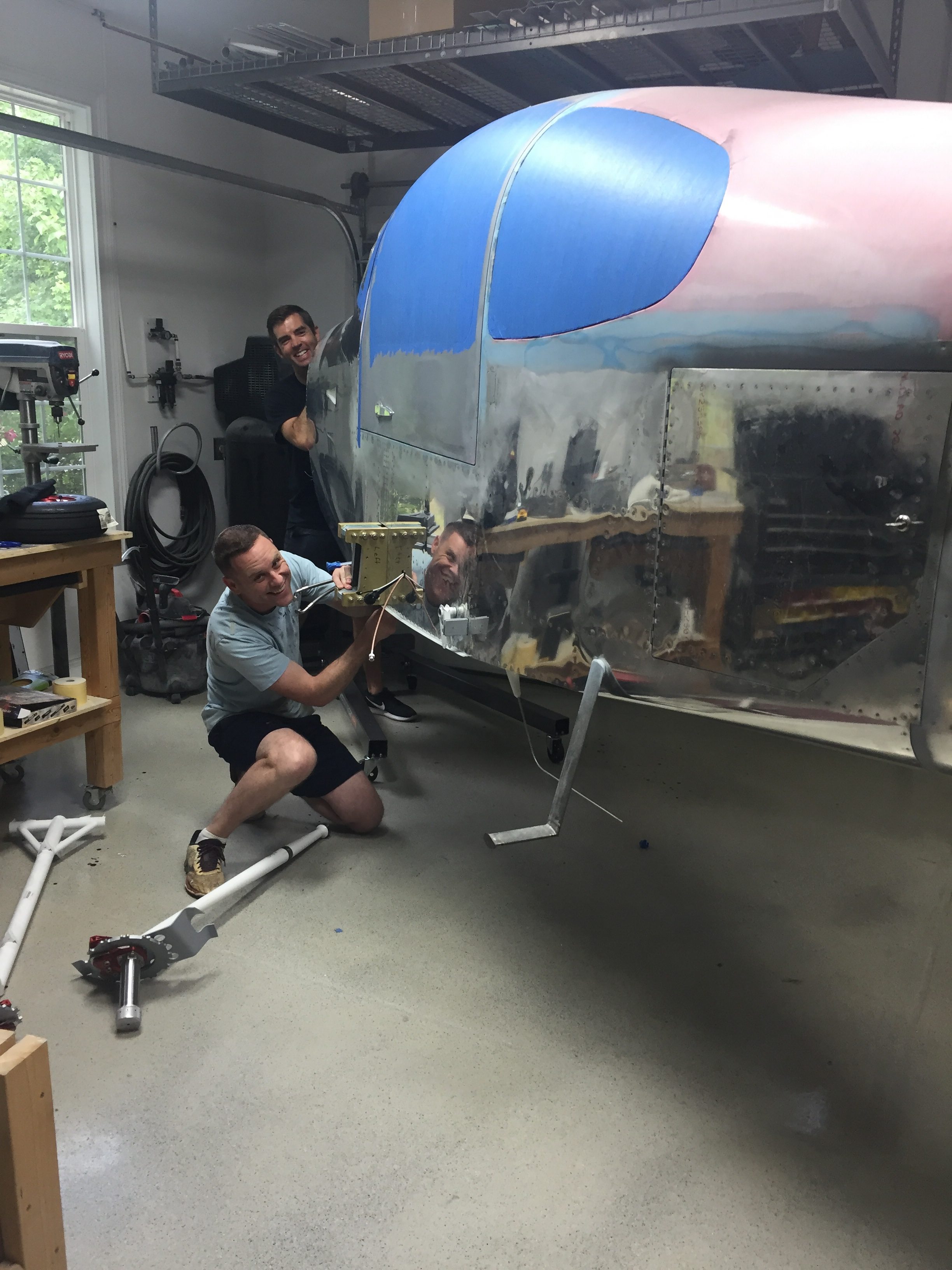
I had already built up the brake calipers and wheel pant mounts to be ready for the install and to be able to do that on the bench vs on the floor. With the Beringer setup, a lot of the setup is different but ends with the same result. The spacers are all machined and an extra hole has to be drilled in the wheel pant mount. A larger hollow axle slides over the stock axle area and a pin is used instead of a through bolt. The Beringer items are such quality and fit great. I did have to dremel a bit of the pant mount to clear the gear leg since it’s slide inboard a little bit.
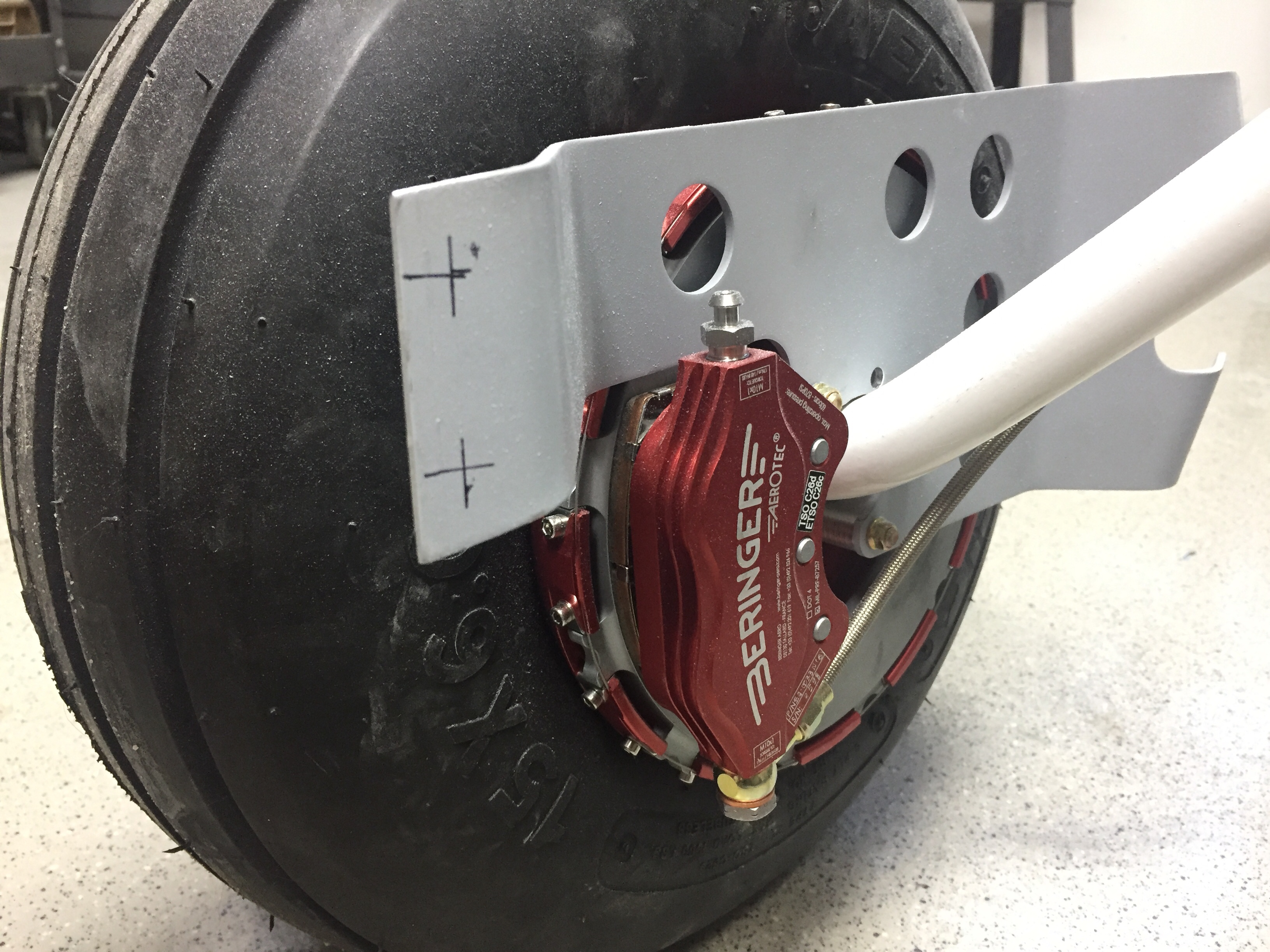
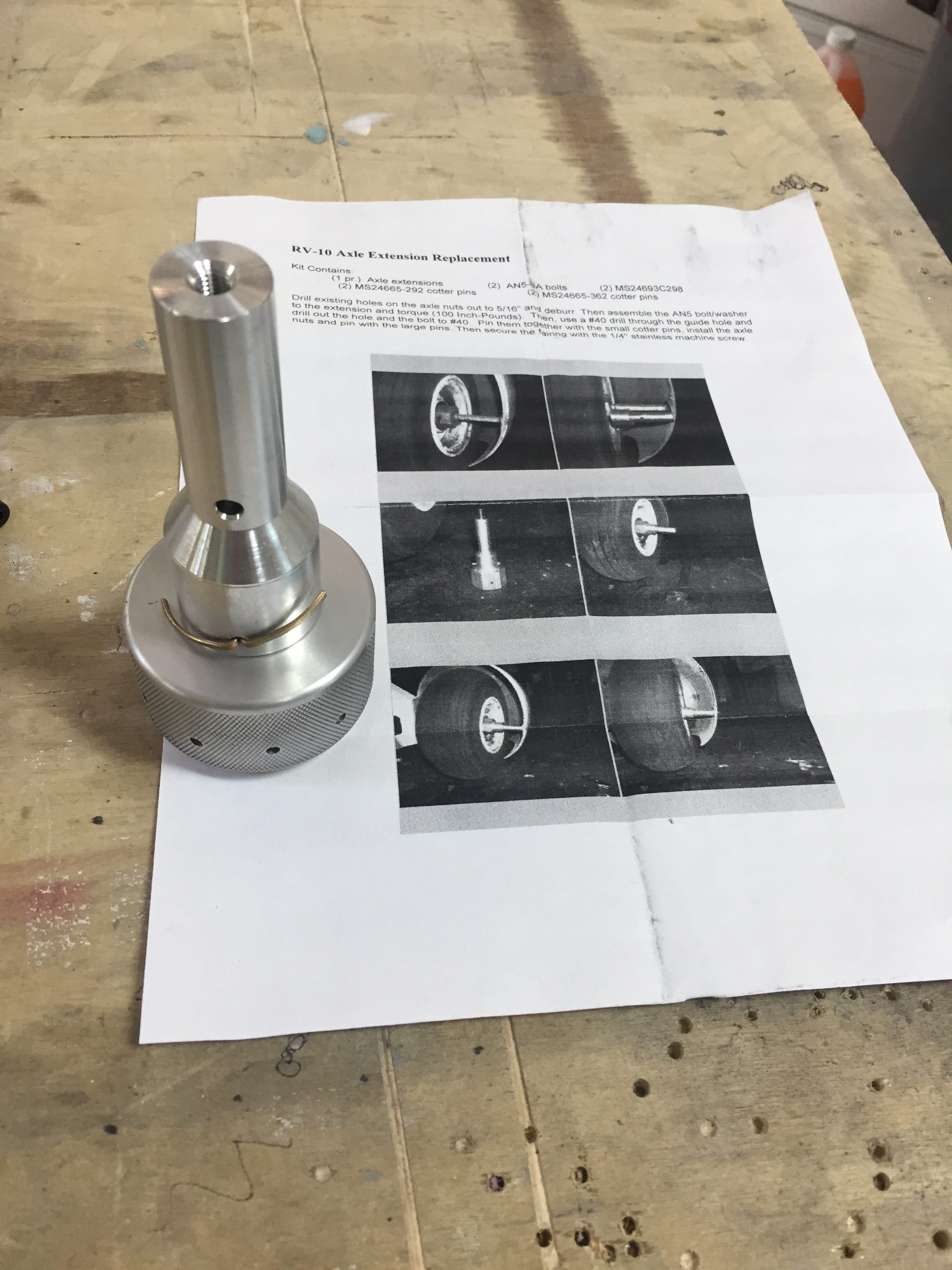
The left leg put up a bit of a fight, as I didn’t sand down the edge of the powdercoat so it didn’t want to slide all the way into the mount. Once I figured that out, I made sure not to learn from it and pressed on drilling the hole for the bolt. Yet again, very anti-climactic for such a momentous achievement! We slid the main wheels on and lowered it down onto the gear for the first time.
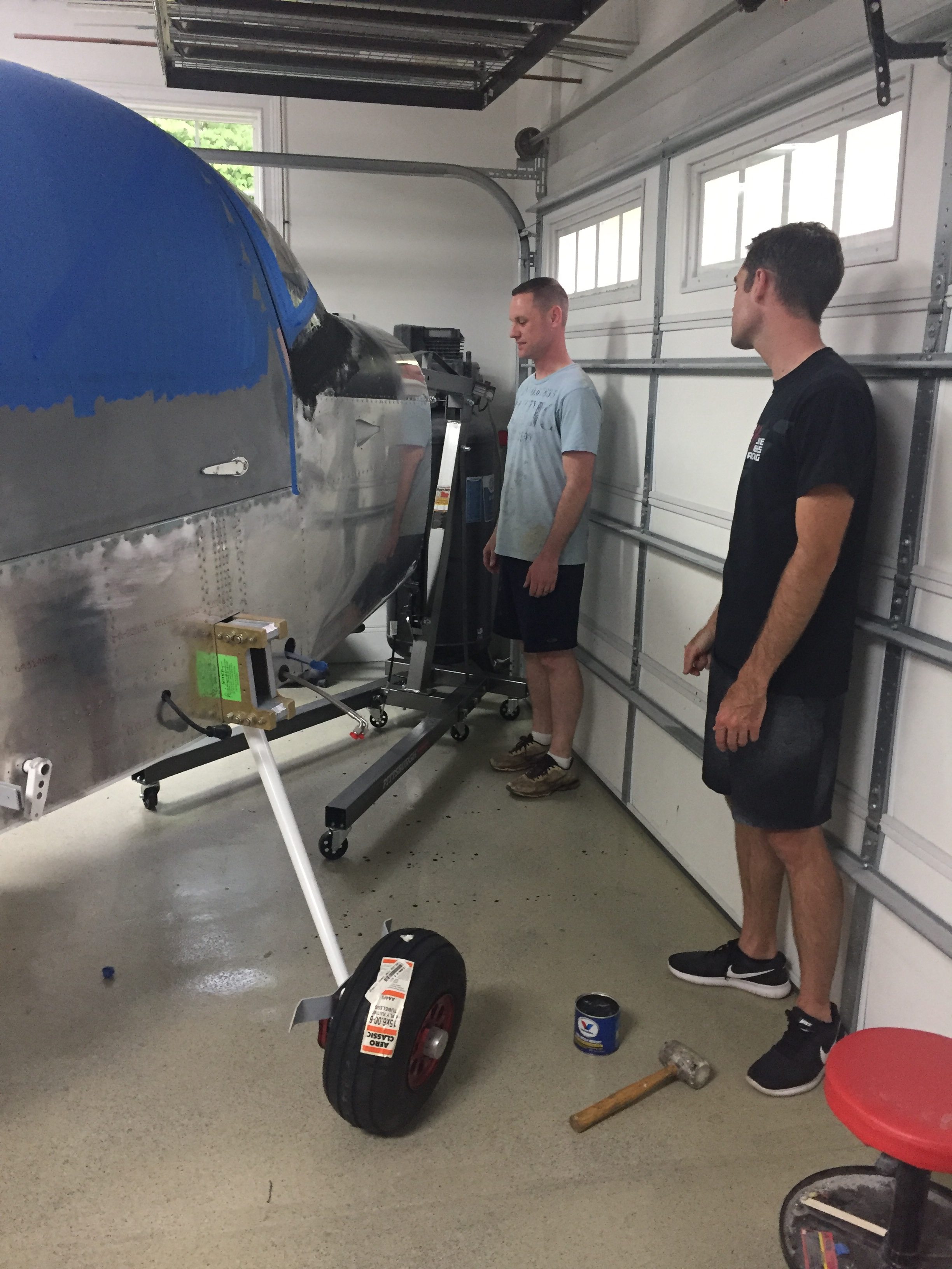
The nose gear leg was bolted on pretty easily and we were ready to compress the pucks/strut to get the cap and bolt on next. Remember when I said I was sure to not learn from the powdercoat edge? Yeah, we spun our wheels and cranked on ratchet straps for an hour with no luck getting the strut cap to aling properly. Clearing my head for an hour to go get more tools helped me finally learn and the lightbulb popped on to sand the strut a bit. The cap fell into place easily after that and didn’t require nearly as much compression as we had initially put on the gear leg.
The next bit of ignorance on my part came in putting the bolt through the cap. The plans called for it to be inserted from the starboard side. I thought, it doesn’t matter. Well, Tim, it does matter. Follow the plans! The hole is slightly twisted to clear the heat vents. I wound up getting it in from the port side but made it difficult for myself.
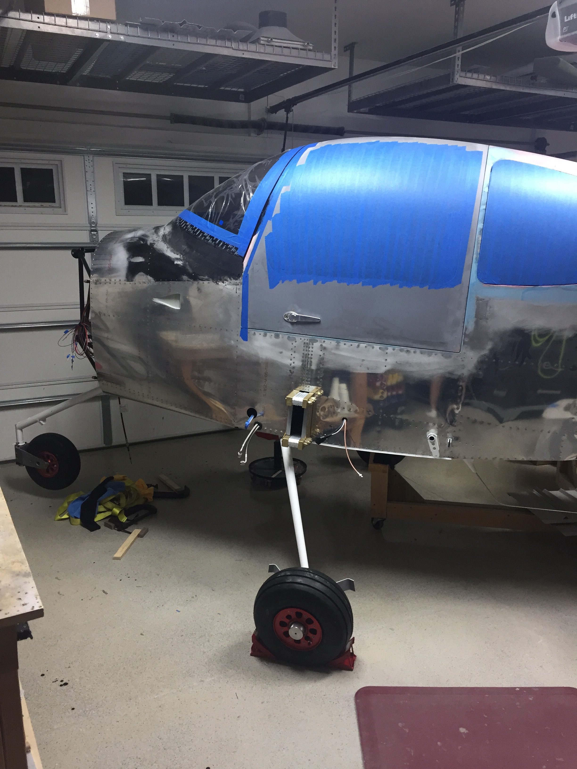
With that complete, the nose wheel went on and she now has her legs under her! The Beringer wheels look amazing, too bad they will be hidden under wheel pants. I left the tail stand on until the engine is hung but still had to chalk the mains since it rolls so easily! I took advantage of the new mobility to roll Tess outside for some sunshine and a good shop cleaning.
