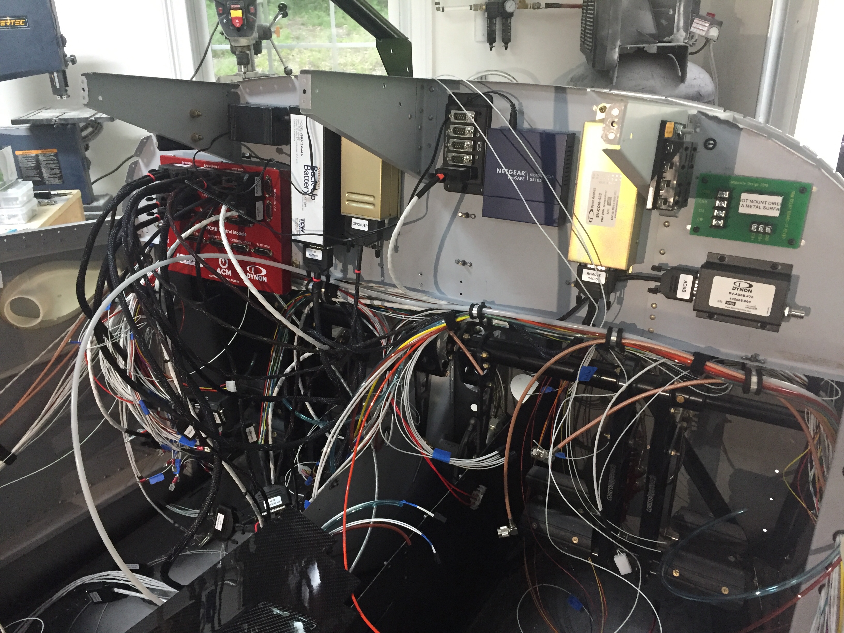
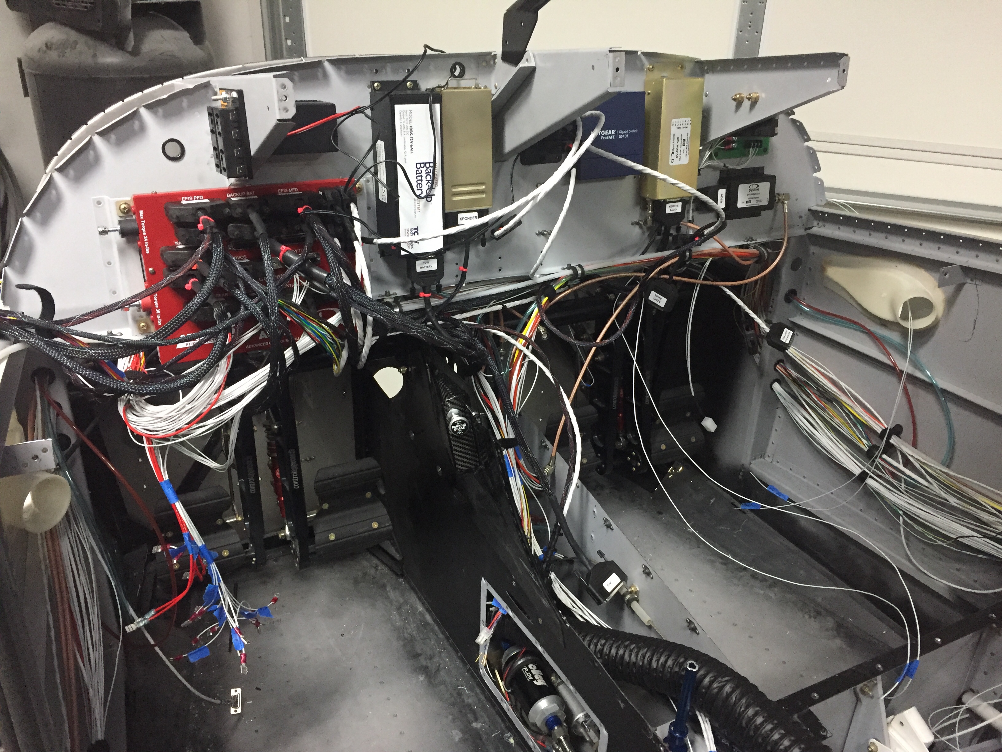
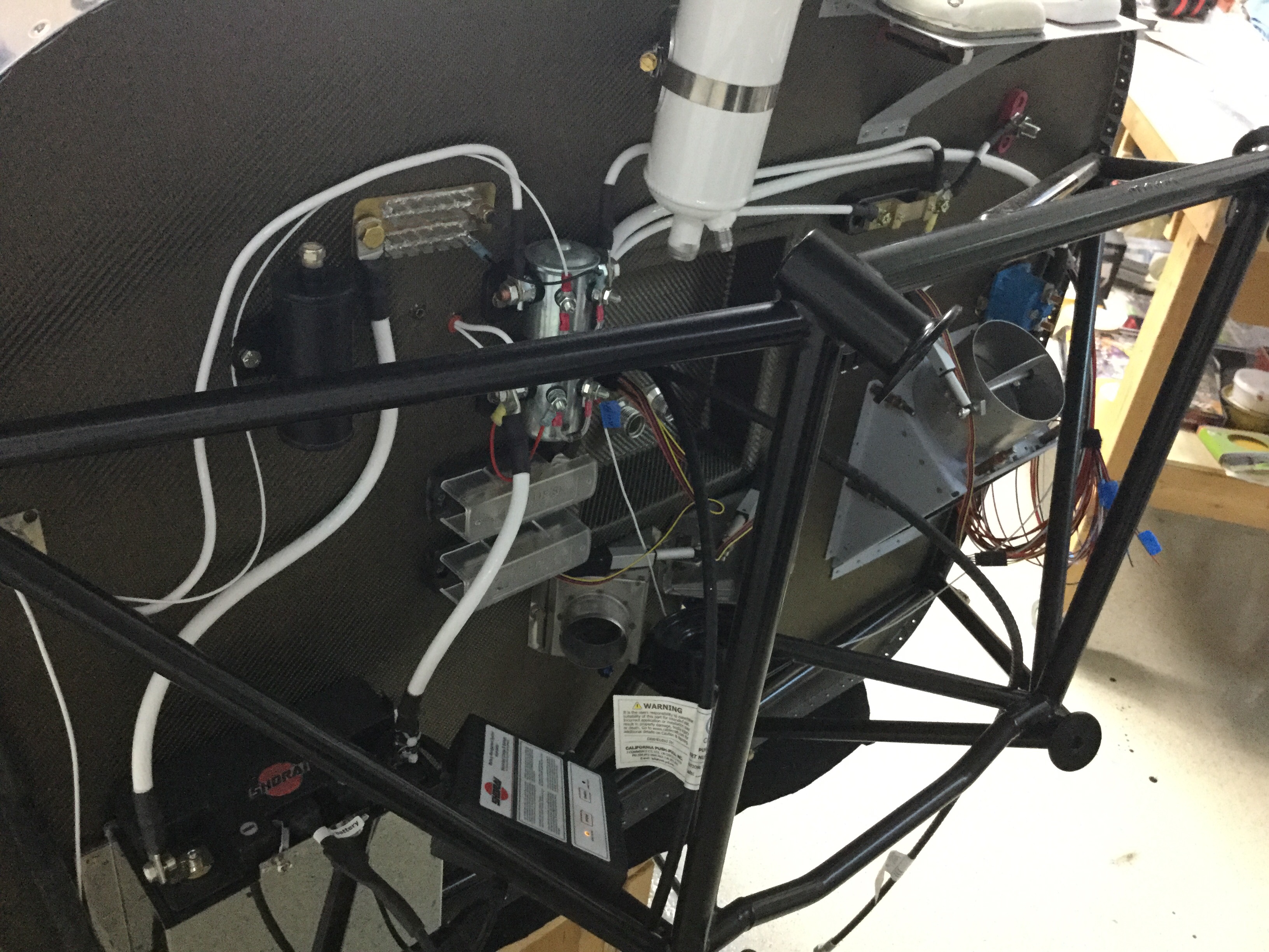
Wiring continues as I think I’m nearing the end only to discover more runs that need to be installed. I reworked the nutplates for the back up battery on the subpanel and have the subpanel back on the fuselage temporarily to continue bundling wire runs. The amount of wire I hadn’t thought of is a little higher than I was expecting, as I thought I had a good handle on the “pre-work” for the avionics. Rudder trim board, a few relays, the lighting control module, and a few others all popped up as I put components in place. I’m working hard to keep the runs neat and tidy as I go. I’ll ziptie everything in place once I feel that I’m done with wiring but I’m sure I’ll forget one or two and need to redo the zipties.
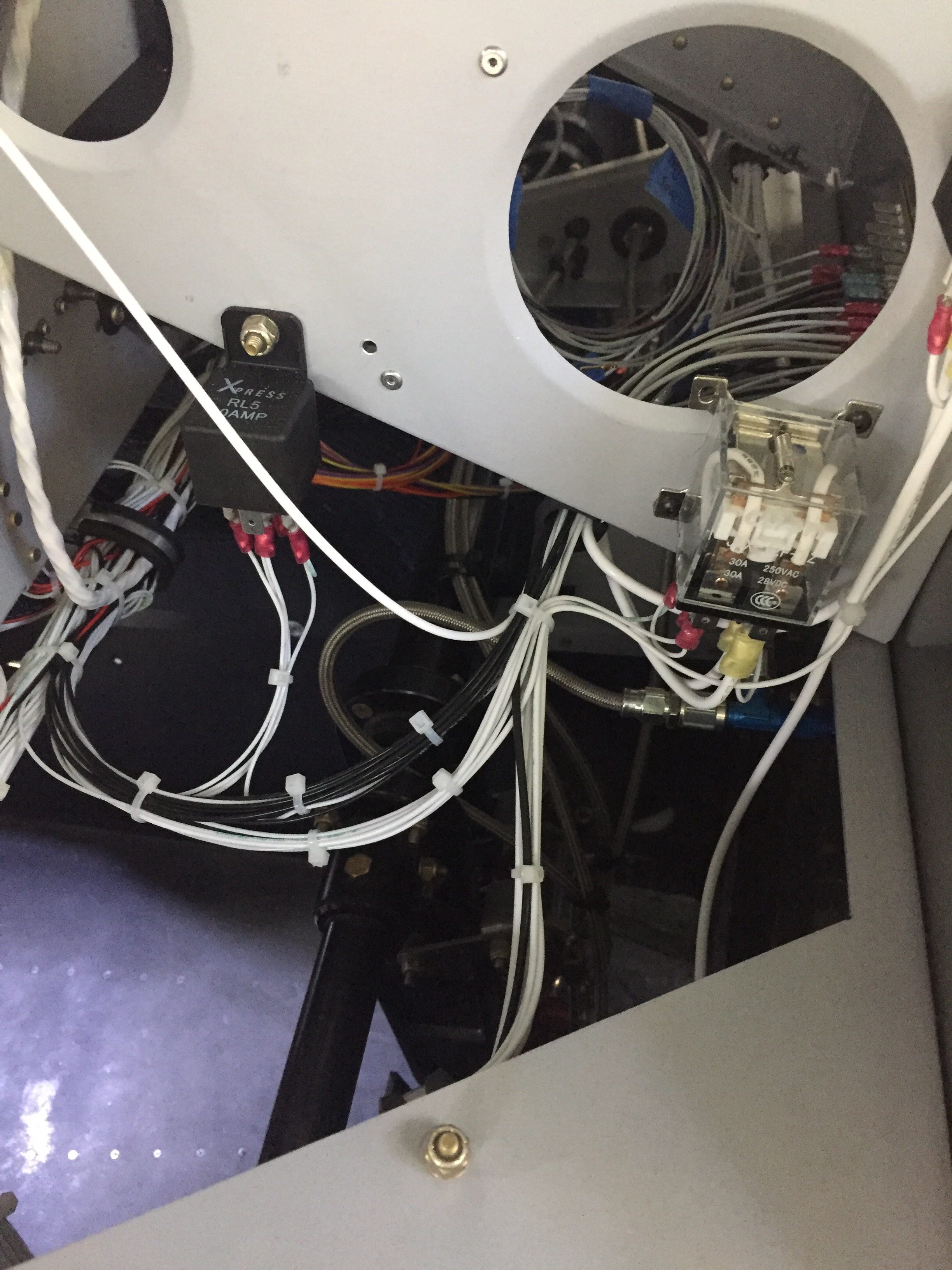
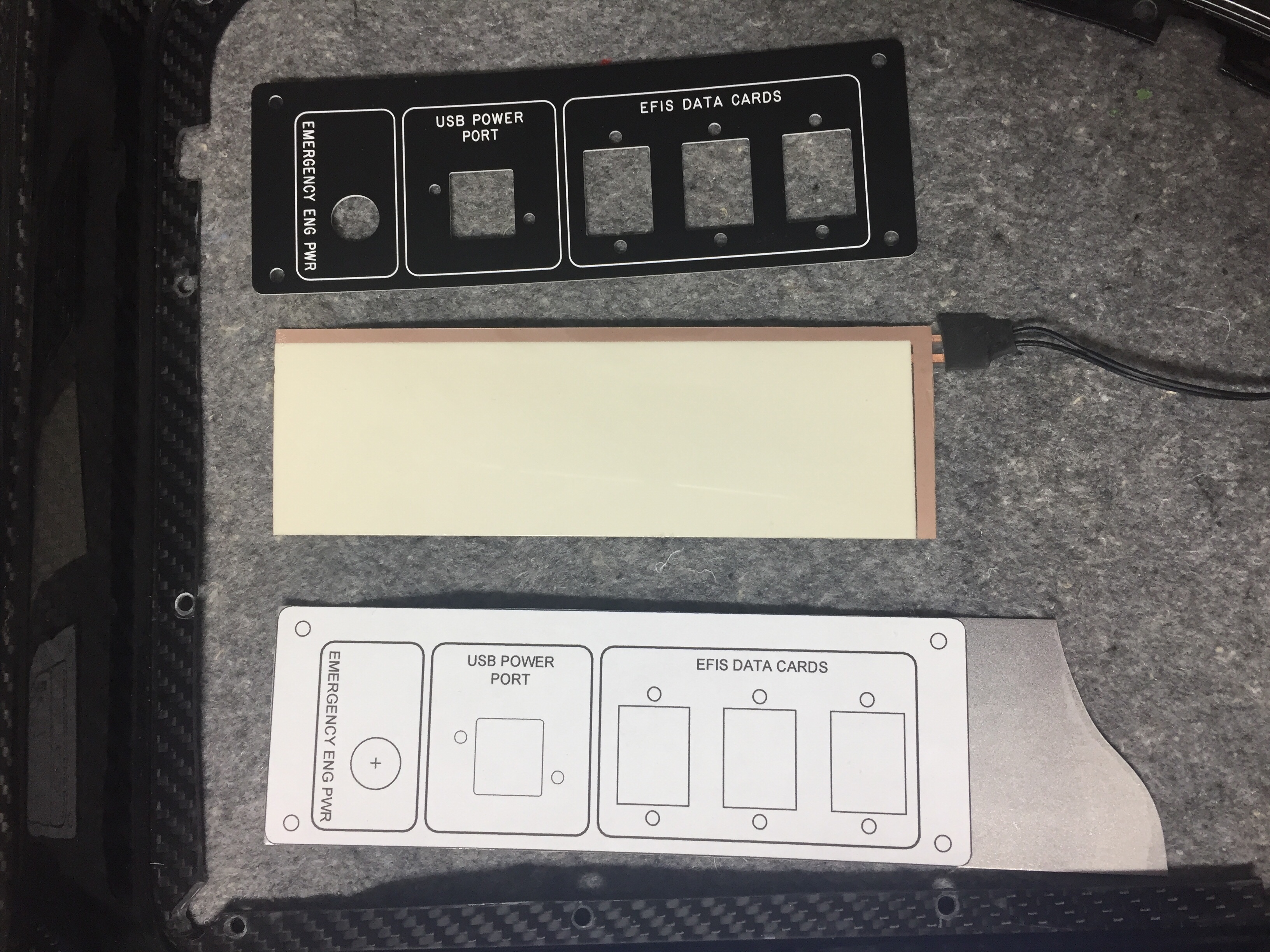
I had to have one of my panel overlays re-etched since I decided to add an emergency power switch for the engine bus. I had originally designed a two relay system that would automatically provide backup power directly from the battery to the engine fuse block (bus) should the main power supply fail (master contactor, etc.). A three position switch would be off, armed, and test allowing the system to be tested before flight. I decided it was too complicated and didn’t design the panel or schematic for it, but now regret that. Essentially, it is only redundant for the master contactor, but now that I’m visually seeing the path of power all going through the contactor as a single point of failure, I want a backup. So I’m running a DPDT 40 amp relay from the battery to the engine buss. I had considered a diode which would isolate a short in the main system but decided to not plan for multiple modes of failure. The switch will be red guarded and the second pole will have be an input for EFIS annunciation to verify the relay’s activation.
I also forgot about the control stick wiring, which is the last connector needed for the ACM to be fully plugged in. I don’t want to fit my control sticks until I rig the surfaces, as the throw of the stick as is now is greater than when properly rigged. So I pulled wires, labeled them, and terminated them on the ACM side. This is when I realized I went a bit overboard on the number of switches on the sticks. I had planned on the typical Coolie hat trim switch, PTT, AP disconnect along with a TOGA, rudder trim toggle (horizontal orientation), and possibly a IDENT or comm swap. It’s a lot, I know. The Tosten grips have all that but I found out that I can’t use all of them! The AFS/IFD setup doesn’t have an input for a TOGA as discovered after a lot of research and question asking. The AP simply auto sequences the MAP based on the flight plan so no need for a TOGA. The downside is not being able to go missed earlier than the MAP while on AP, something I’m used to in the Diamond with the G1000. Not the end of the world. I decided against a IDENT and comm swap switch as I just think they are not needed since I have to touch the panel anyway and I mean seriously, am I that lazy?? Ha, yes I am, but those two features still didn’t make the cut. So, I wound up with three axis trim, PTT, and AP disconnect (AFS calls this CWS which it’s not but whatever). A TOGA is reserved as a coming feature from AFS.
The GPU receptacle is also wired up now in its hidden location under the copilot’s seat. I wired the GPU contactor such that it will power the full system but not charge the battery, as the Shorai will have it’s own balanced lead to connect the dedicated charger on the ground if needed. Because I’m electron dependent, I will never jump a dead battery and take off, so no need for external access. The GPU will be in the hangar for maintenance and/or learning the avionics. I cut a little flap in the seat foot well wall and mounted the receptacle to the seat rail support. It worked great and will have one bolt on the seat bottom to help secure once that area is all complete.
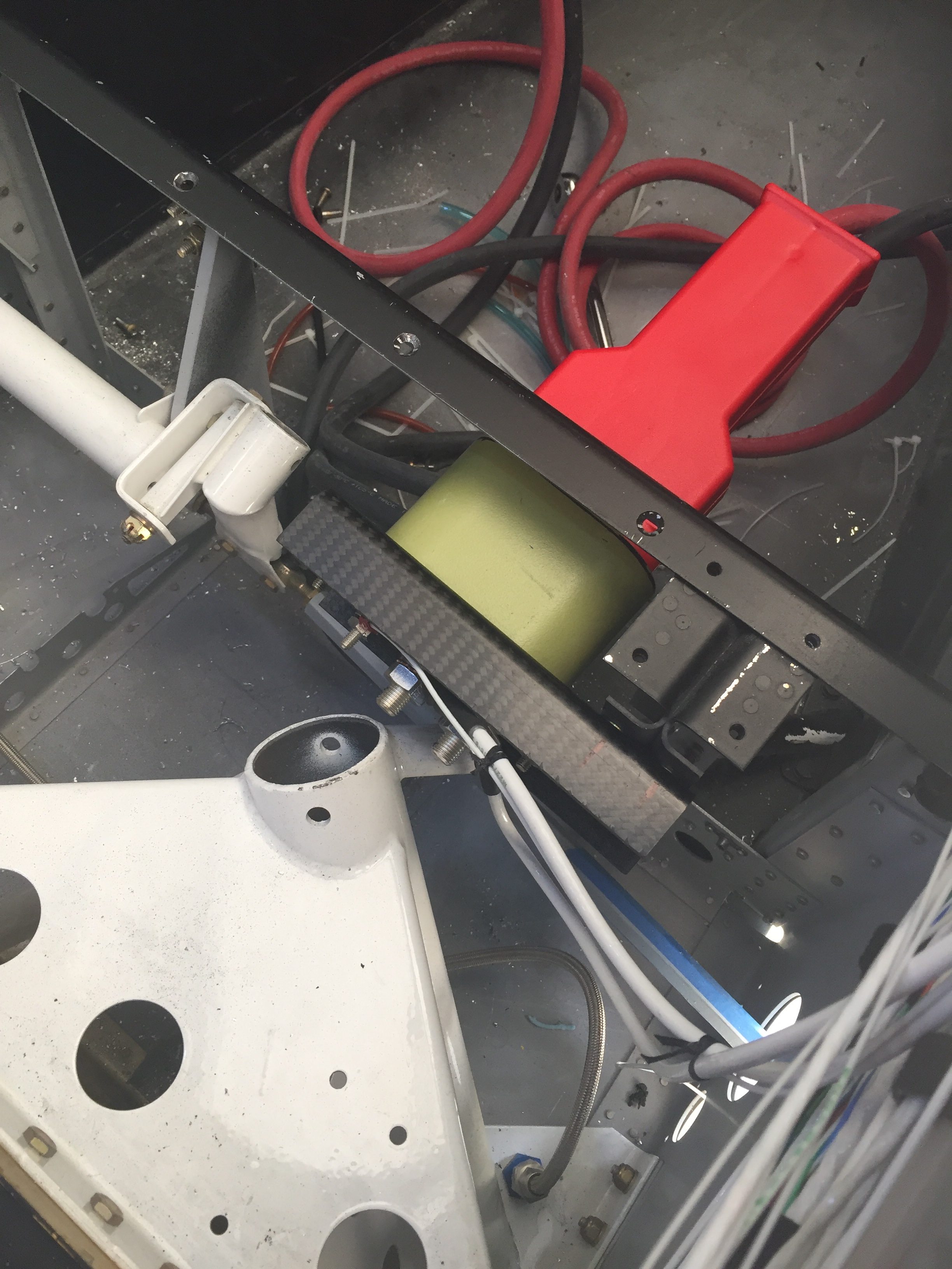
The big wires were taking up a lot of room on the shelf and with the components on the firewall all mounted, I could get the thick stuff installed. I took some time to determine what size lug would be needed at each end of wire and ordered all the supplies in. Great move because I had all I needed plus a few spares of everything. The crimper I bought from Amazon worked well and it was a pretty easy, fun job overall. It helps me visualize the power system now even better and I’m happy to say that I feel safe and secure with the architecture providing power for the plane.
After receiving the newly etched panel, I could fabricate the last of the switch panels so the avionics would be ready for final install. Just like all the others, I started with a printed 1:1 image of the panel I had designed spray glued onto the aluminum sheet. I cut that out then final trimmed it using the acrylic overlay before painting it black. The back light panel is placed on the aluminum panel and positioned using the overlay to get it just right before trimming for the switch and USB ports. This one was pretty easy with large cut outs. I use 3M double sided tape to secure the back light panel then lay the adhesive backed overlay on top to finish it all out. I use a Sharpie to color the white on the edges of the overlay to help control bleeding from the back light and give it a nice finished look. I did have a little trouble with the wires on this panel and wound up replacing it all together with 22 AWG Tefzel soldered on the panel itself. I wish I had done that with all the others, as the wire used from the panel is crappy and hard to terminate using the micro-molex connectors. It turned out great, though, and is the last piece of the instrument panel.
Finally, I worked up two brackets for the micro switches on the doors and wired those along with the one on the baggage door for the lighting control module. I also used the micro switch on the baggage door as the safety switch input for the EFIS annunciation. More wires to run, oh boy. A pretty quick job that should work just fine. I did have to run an additional wire up to the overhead as I had picked up power and ground for the door lights from the overhead lights and that’s not how the lighting control module is set up.
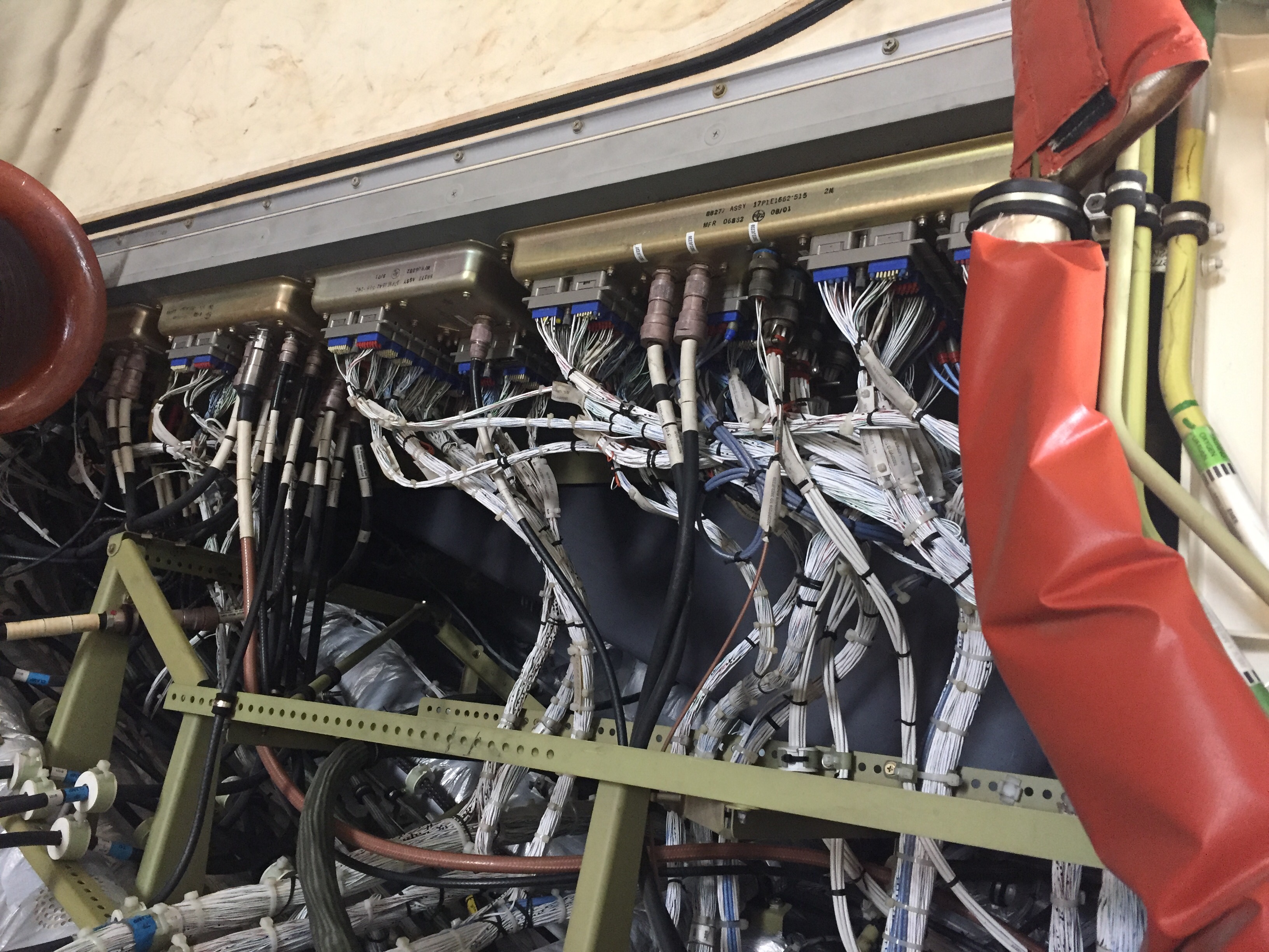
While my plane does have a lot of wiring, it’s nothing compared to the big boys at work. This shot is behind the port side avionics bay in the C-17. Now that is a lot of wires!
