This Bird is Squawking

I will document the biggest and most annoying things wrong with the airplane during the test flight here but do not plan on blogging about every repair or modification to the airplane. Mainly because I’d have to become a full time writer.

The flight tests went fairly smoothly and I finished the 40 hour phase 1 in under a month. Most of my issues were builder caused, I must admit. Either a rework or bad soldering, decision making or lack thereof, and a few “that’s good enoughs” that came back to haunt me were to blame.

I tracked these by creating a list in my phone/iPad that I could check off as I corrected the issues. The list kept growing for some time before it started getting checked off. It’s worked really well for me and actually motivates me to complete all the repairs or adjustments to get the check boxes checked. I can also make group entries into the logbook to keep track of the work.

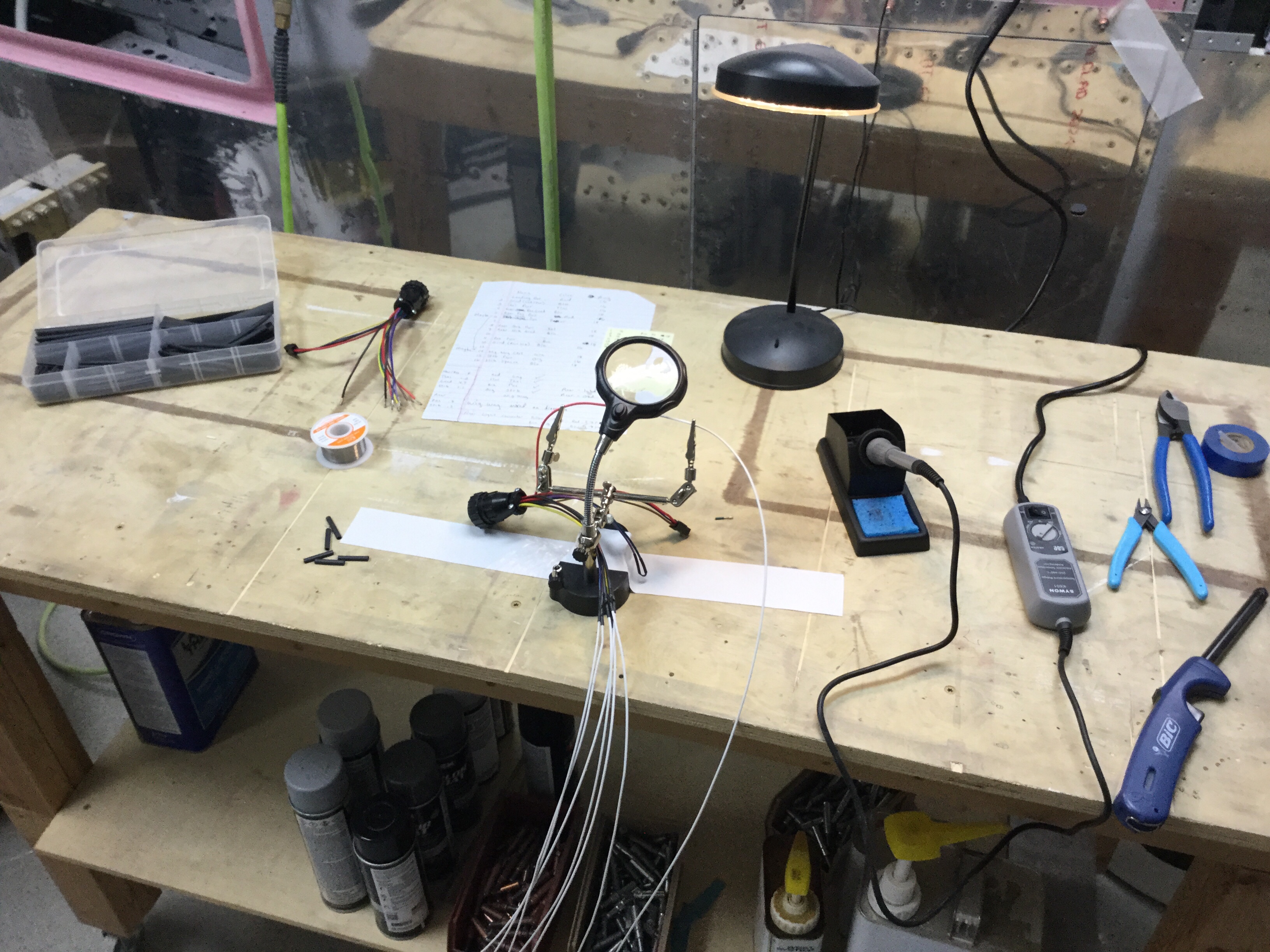
I found that I had a lot of electrical gremlins throughout the first bit of flying. Solder sleeves are amazing little buggers that are notoriously difficult to use correctly. I used sparingly while building, but they still bit me a few times. The problem is you think the solder ring has melted completely but it hasn’t. The connection will be good until it’s subject to some vibration and then all kinds of weird things happen. My oil pressure spiked to 200 PSI, multiple random annunciations based on my discrete inputs, and a few others due to the solder sleeves. And I only have about 10 in the whole plane! I will use them now if I have good access to the connection, but if not, I’ve found using Dsub pins and heat shrink as more reliable.

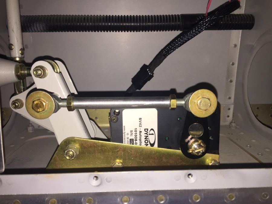
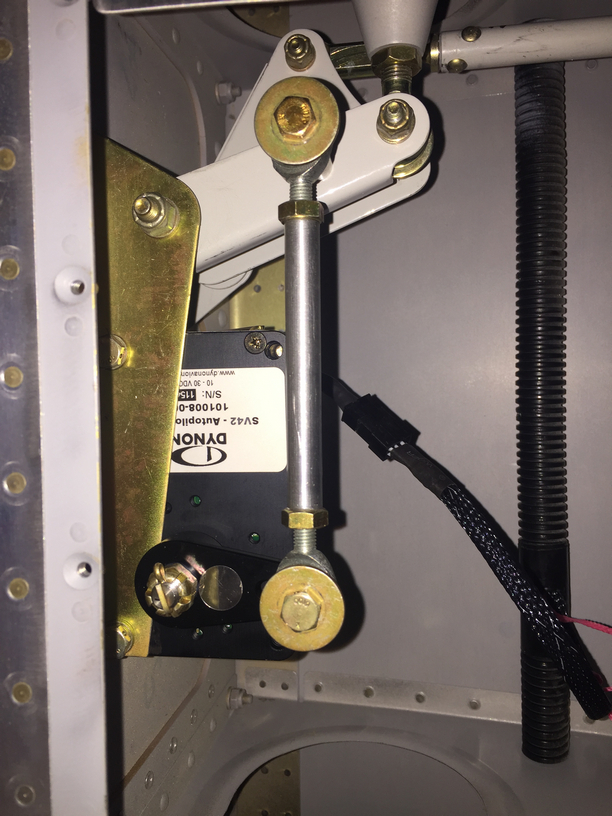
I had to reposition my EGT probes, as I realized they blocked 5 out of 6 spark plugs. I had a master cylinder bolt leaking just a bit. Lots more clamps and zip ties were installed, mostly firewall forward, to avoid chafing after a few oil changes and seeing where things moved a bit too much. I had to replace the autopilot pitch servo due to a service bulletin, roll servo due to slipage, and had to reinforce the rudder trim tab mount to get it to work effectively. I chose to rewire a few engine switches and add a engine master switch, which I should have done in the first place. That all neccessitated under the panel work, a new switch panel overlay and backlight sheet. The oxygen system leaked above 1200 psi (loose connection), and a few adjustments to the door light switches have been made.
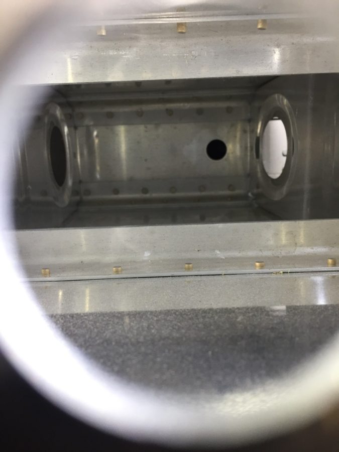
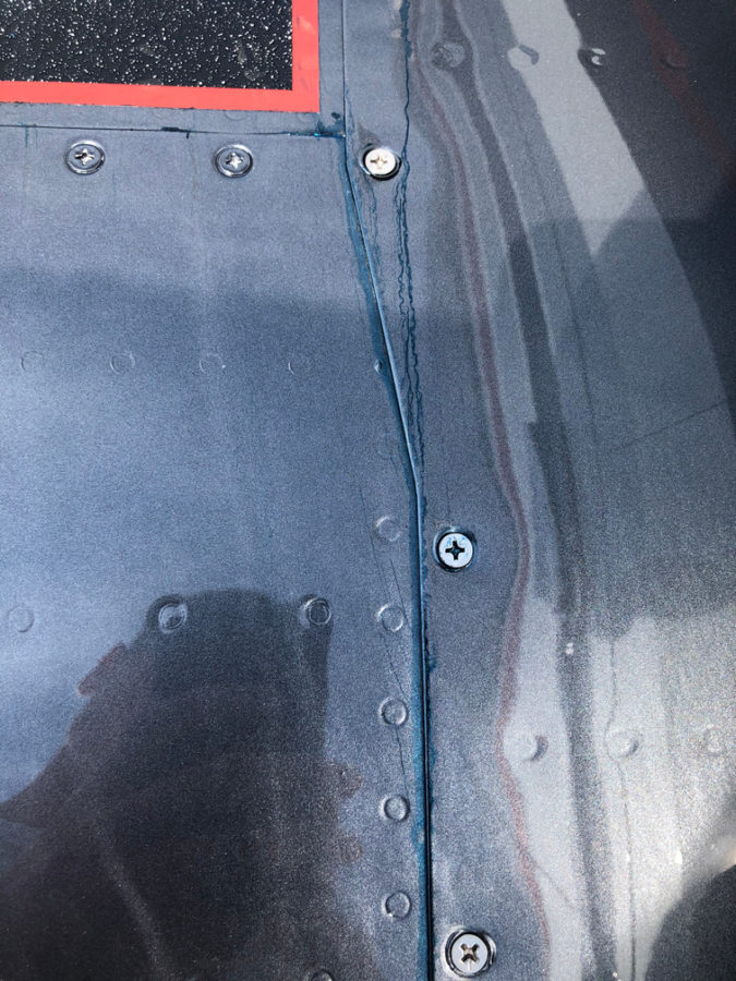
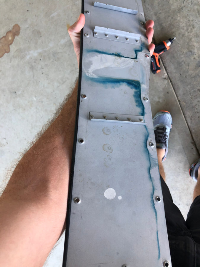
The biggest squawk is a leaking fuel tank. I am getting ahead of myself on the blog, but this was discovered post paint unfortunately. Turns out a little weeping rivet that I discovered prior to paint and thought I had fixed with the Loctite trick wasn’t fixed. In fact, it wasn’t a weeping rivet, but a pinhole in the sealant on the rear baffle. Fortunately, I spent an entire day and was able to use my borescope to provide a view and a coat hanger/tube of pro seal to apply sealant and fix the leak without taking the tank off. Not a fun job.
The engine ECU tweaks were pretty easy, although I’ve gone through four O2 sensors (leaded fuel doesn’t make them last long). I removed the air filters and just installed a mesh screen over the intakes. Speaking of intakes, one was too close to the exhaust header and a hole burned through it so that required a bit of glass work along with better heat insulation and a bit more clearance.

Lots of other tweaks and adjustments were made and most of these delayed discrepancies were taken care of during the first condition inspection performed in November last year. I do have a few more items to check off the list including new door hing covers, some finish rework on the interior windshield pillars, an intake plenum on the air conditioning condensor (more on that later), and adding a second tunnel access plate are all on the list for 2021.

Bottom line, you’re not done building when you’re done building. Flying brings on new stuff that you can’t forecast on the ground so it’s a continuous process to keep it in tip top shape. I also put some of this stuff off, as I wanted to get it flying so its been a challenge to get caught up after flying so much. I am now at a point where the regular maintenance time is decreasing vs the flight time increasing. The check boxes are all most all filled in!

Stabilizing success

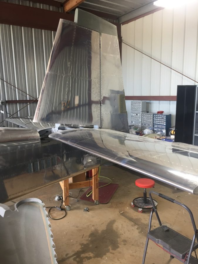
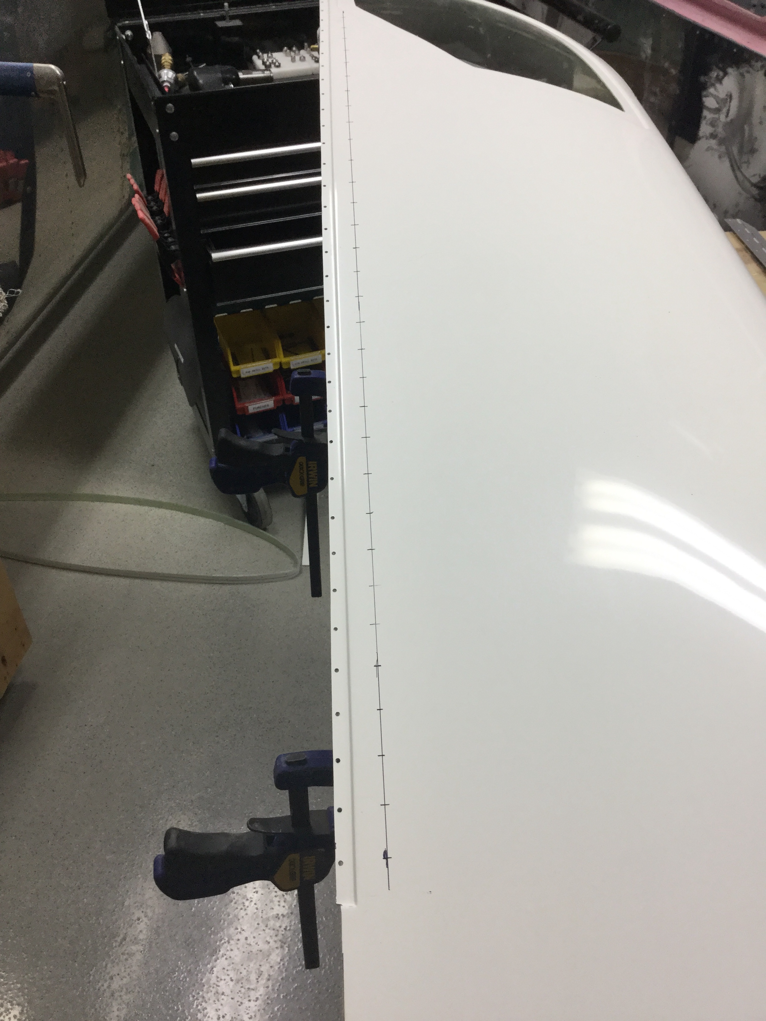
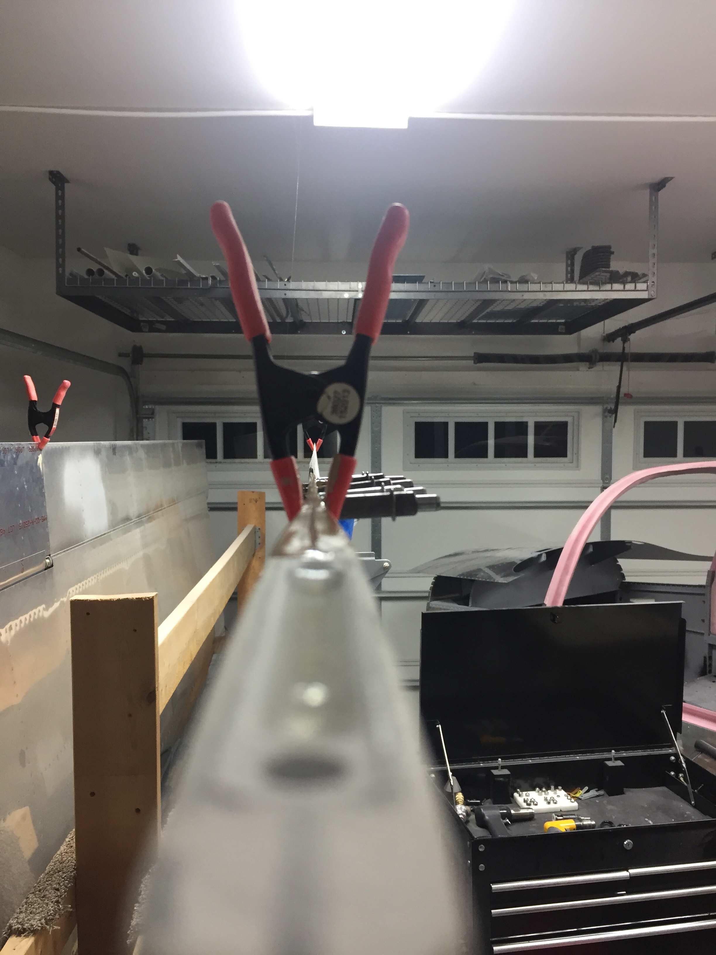
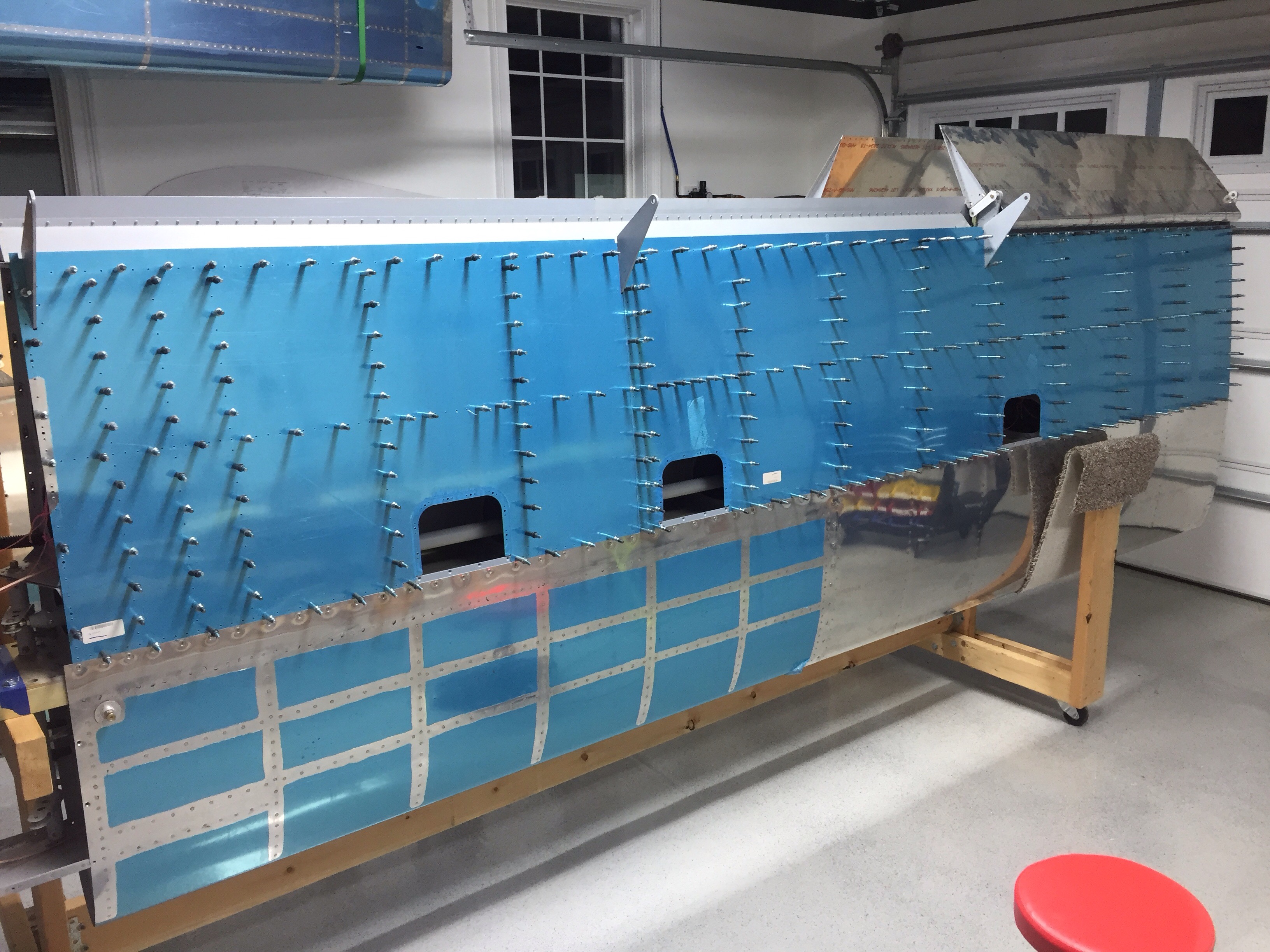
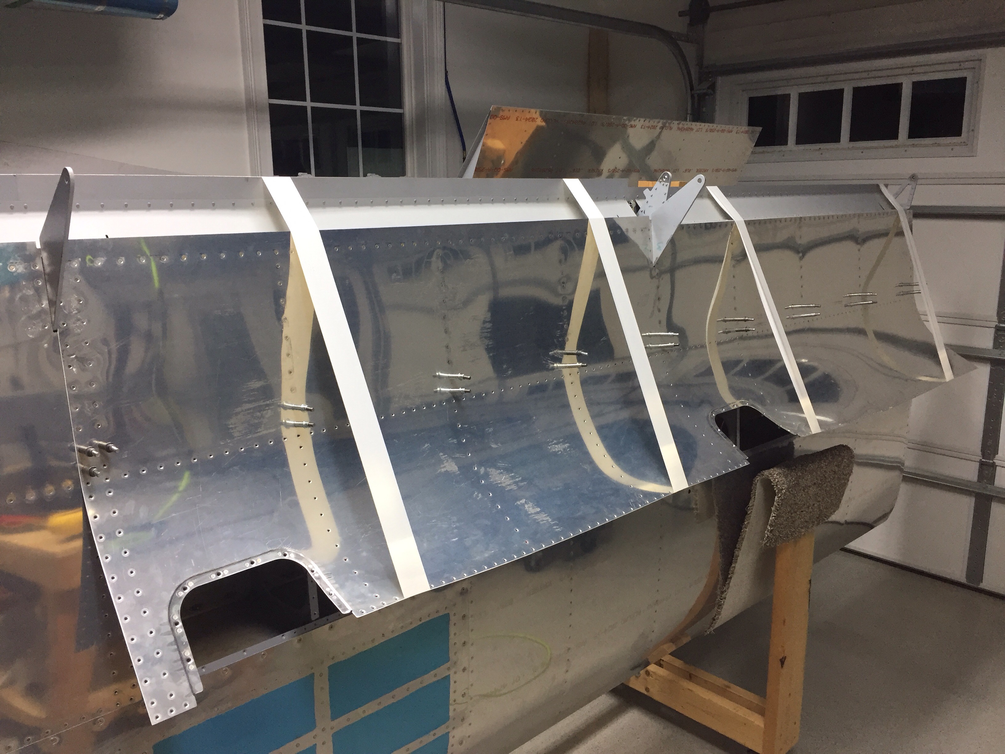
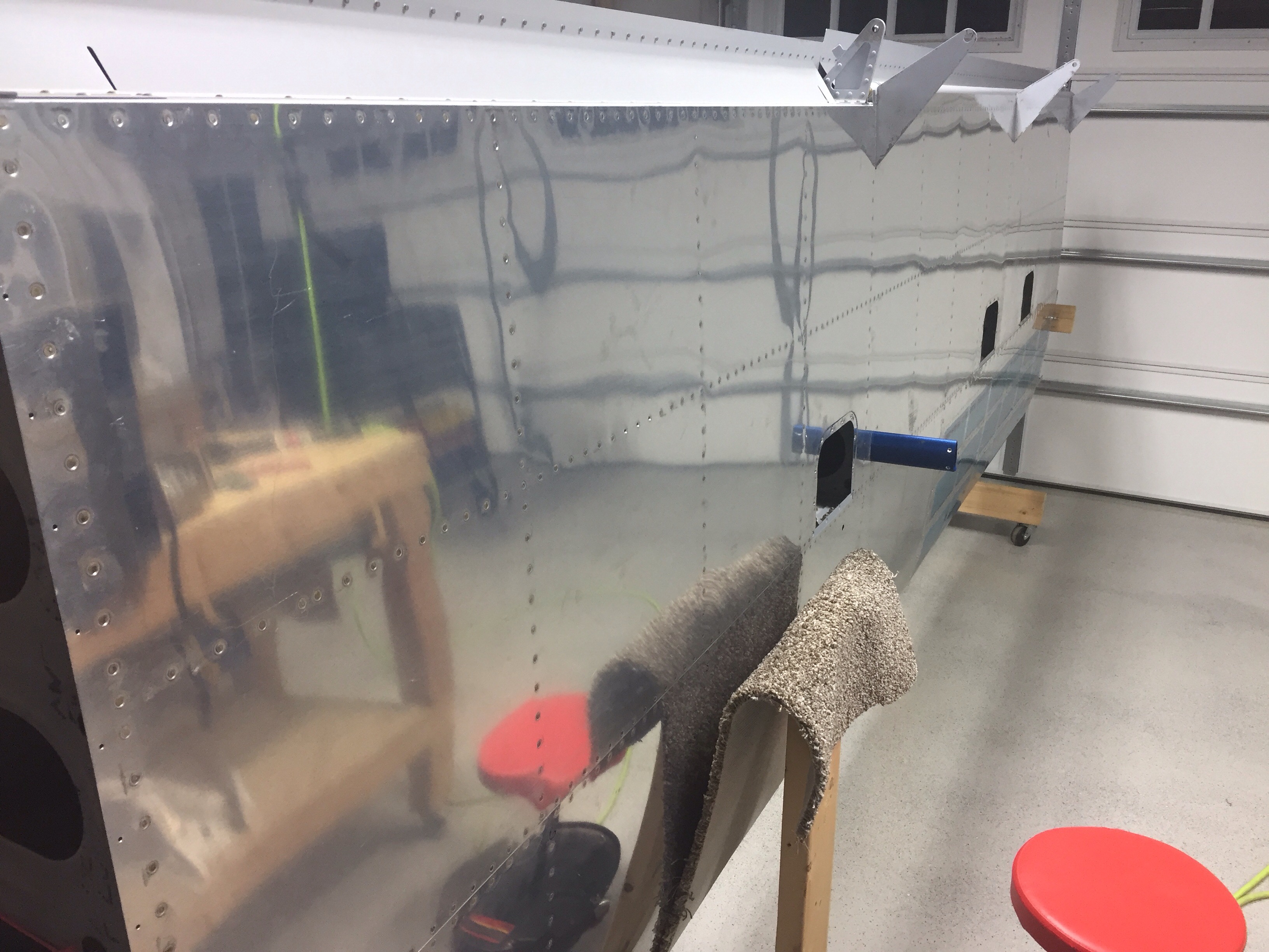
I skipped a major step during the tailcone build sequence by never installing the horizontal and vertical stabilizers onto the tail cone. I didn’t see a point of doing that in the garage just to take it all apart again for storage for years. Now that I’m in the hangar and have the room, no excuses are left. I didn’t build either stabilizer, as the original tail kit owner built them. After looking over them and cleaning them up, I “touched up” a few of the rivets I felt were under squeezed. They aren’t primed on the inside either but even after 10 years of sitting around, they are looking good and corrosion free.

The process went as planned and I spent the better part of one full day getting it all drilled and bolted on. I had purchased the CNC brackets from somewhere to mount the horizontal stab so I didn’t have to make them. I have no clue where I got them from, however, as I bought them on a whim years ago. Either way, they’re nice and you should buy them.

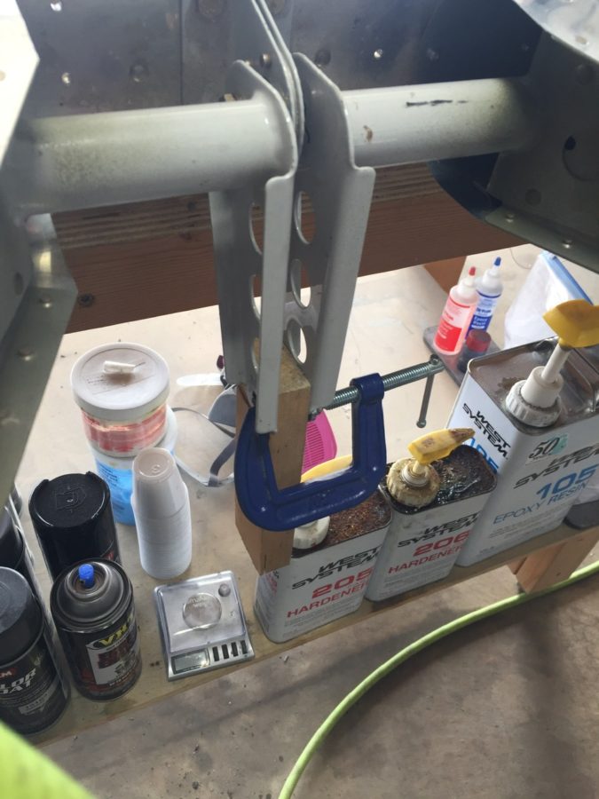
The only hiccup came when working on the elevator trim cable. The original builder had installed the plastic snap bushings the trim cables run through while building the stab. Unfortunately, he put the wrong size bushing in one of the holes that was buried in the spar. The cable wouldn’t pass through. Fortunately the hole was the correct size but man was it a pain in the ass and fingers getting that old one out of there.

Laura helped me bolt the rudder on next to set the rudder cables up and do some trimming for the rudder trim wires and tail light wires. All easy stuff and its really exciting to see the tail feathers finally get attached.

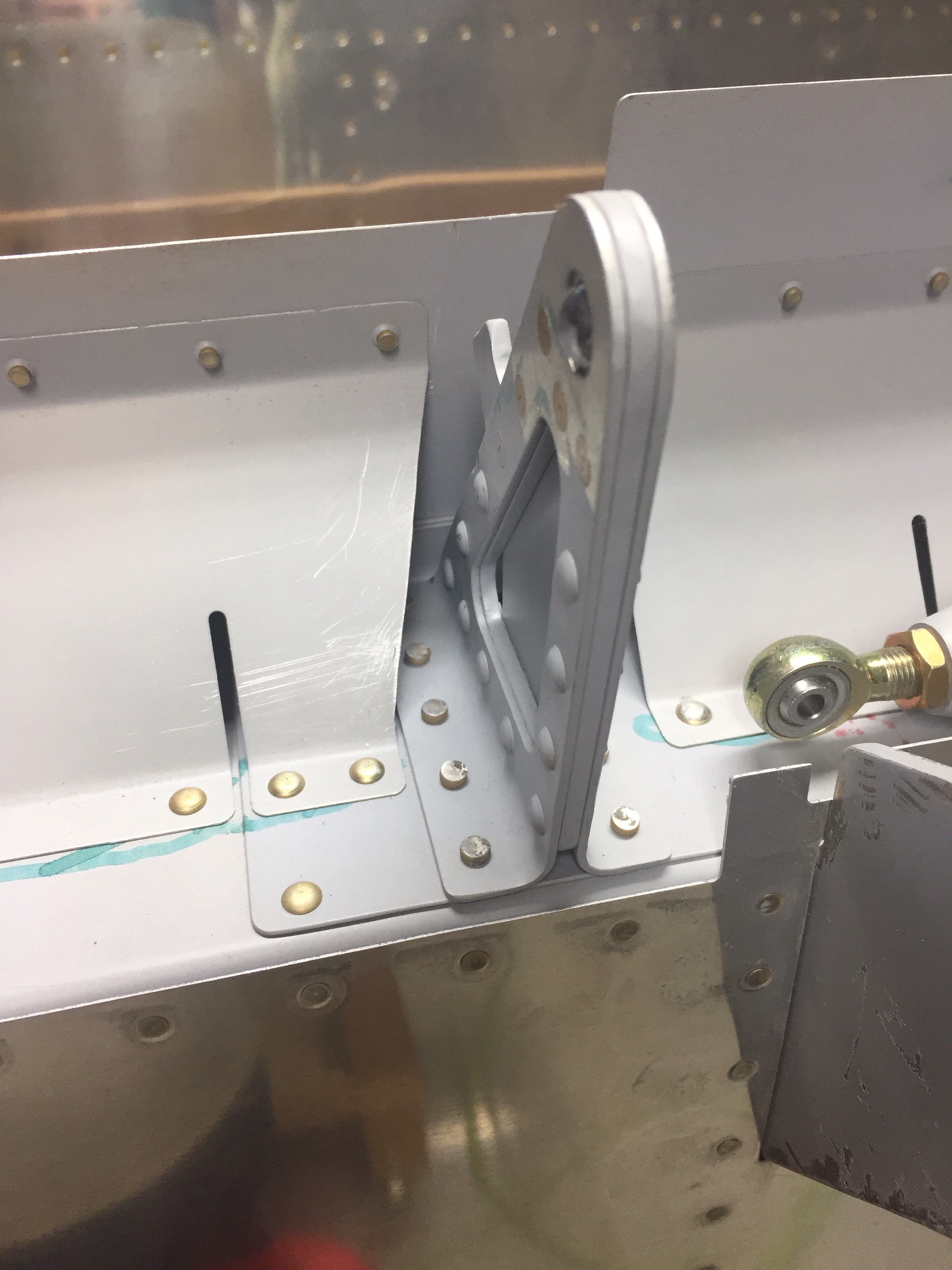
I was able to finally hook up the elevator torque tube after drilling the horns. I was careful to get them lined up accurately and am pretty happy with the end result with the right elevator being lower on the trailing edge by about 1/16″.

I then set out to start the rigging process by centering the stick and adjusting pushrods to get the control surfaces all lined up. It takes quite a bit of stick movement to get the control range established by the plans and I found some interference with a bolt on the aileron rods under the seat pans. I was able to switch the bolt orientation and it cleared right up.

The autopilot roll servo went into the right wing pretty easily as well. I had the mount installed during wing construction, so it was a matter of bolting it in and attaching it to the aileron bell crank. The wiring hooked up quickly since I had already ran the wires and installed a connector.

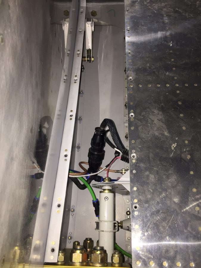
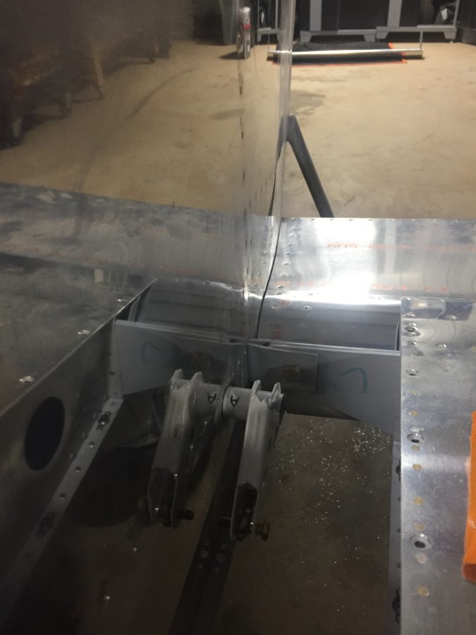
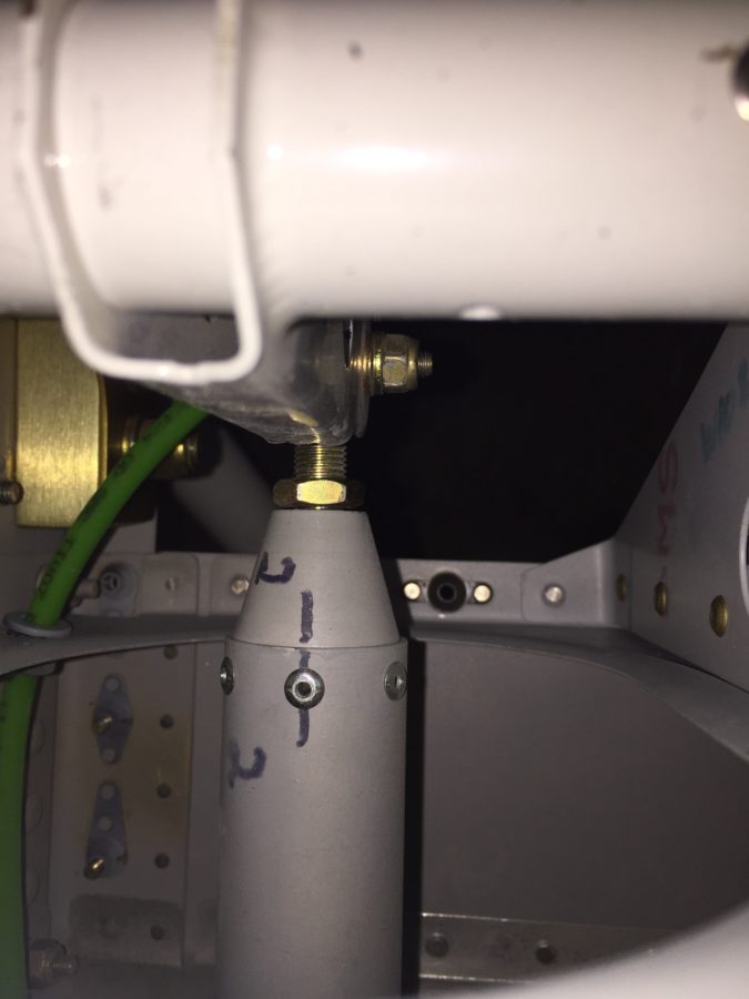
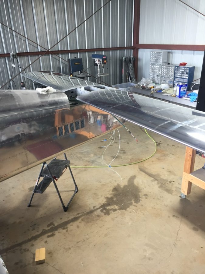
I cleaned up a bit of the wing root area as well, hooking up the CPC connectors, pitot/AOA tubing, and ensured it all cleared the control rods inside. I had planned to mount a bracket holding the CPC and pitot/AOA tubing somehow, but the whole bundle is so stiff, I’m not too concerned with securing it further. It’s also well clear of the torque tube despite the appearance in the picture.

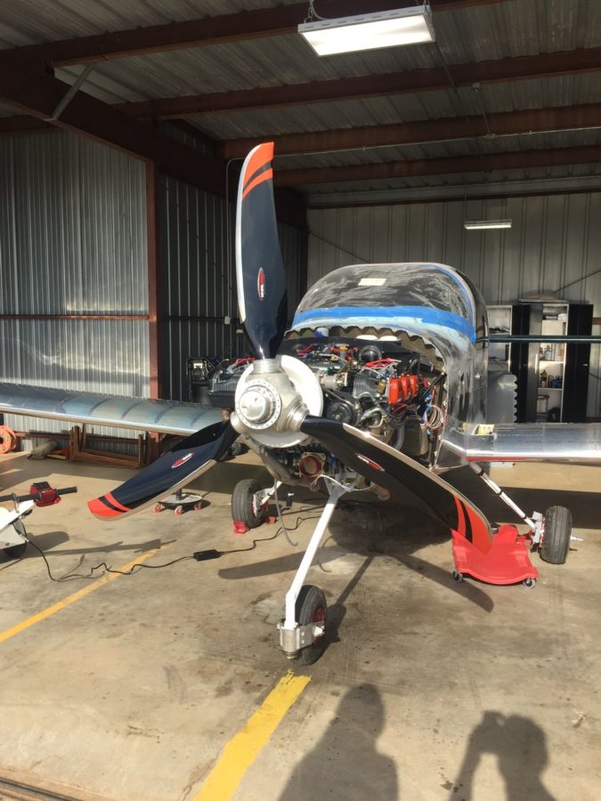
Finally, we had some good light from the sun on the propeller and I couldn’t help but drool over it for a few minutes. The orange over black with the polished leading edges are just too damn cool looking. The scimitar shape is sexy too!

Throwing gas on a fire

I’m getting bad at taking progress photos, as quite honestly I’m under the gun on getting this thing airworthy and ready for inspection by November 12th.  So I’m really powering through a lot of tasks and am so exhausted by the end of the night I just forget to document it all.

We got the wings back on and permanently bolted on.  I had to order a few washers as the nuts bottomed out on the threaded portion before they should have.  I just added one washer on each bolt and got the proper torque value with no spinning in the hole.  I did the same with the main landing gear bolts on advice from another builder who had a bugger of a time replacing the bolts after the holes elongated.

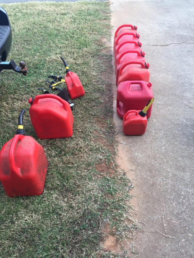
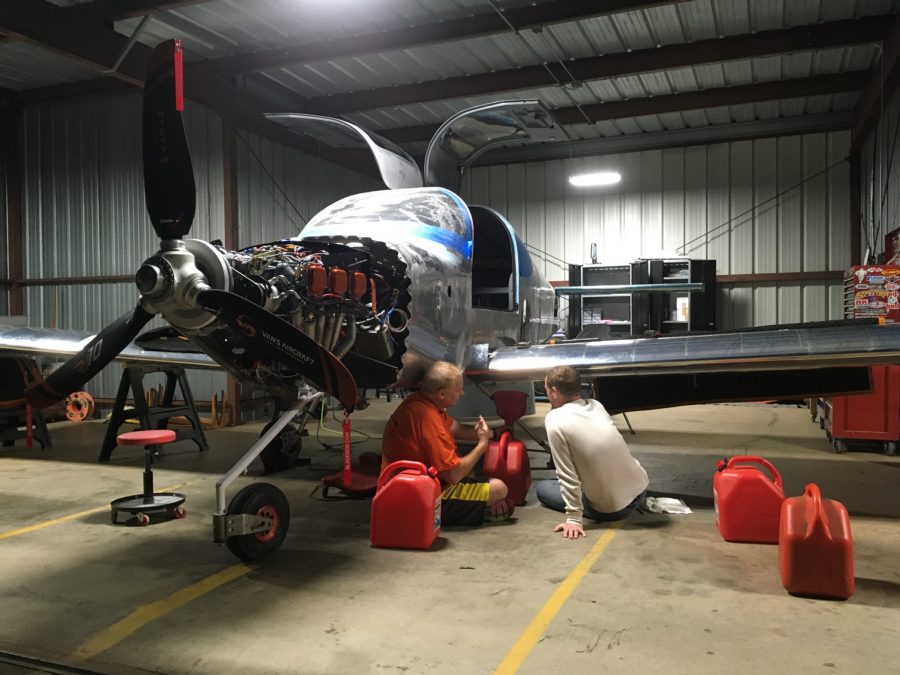
Fuel testing is next on the list and a big hurdle to climb over.  We had pressure tested the tanks, but I was still a bit nervous to put avgas in them for the first time.  I collected all the gas cans I could muster and had enough to hold 36 gallons for the first fuel tank test.  I also bough two two-gallon cans to calibrate the fuel senders.  This test is not only for the tanks, it will see if I have leaks in the lines and will finally show what fuel flow the pumps provide, a key test point for first engine start and flight.

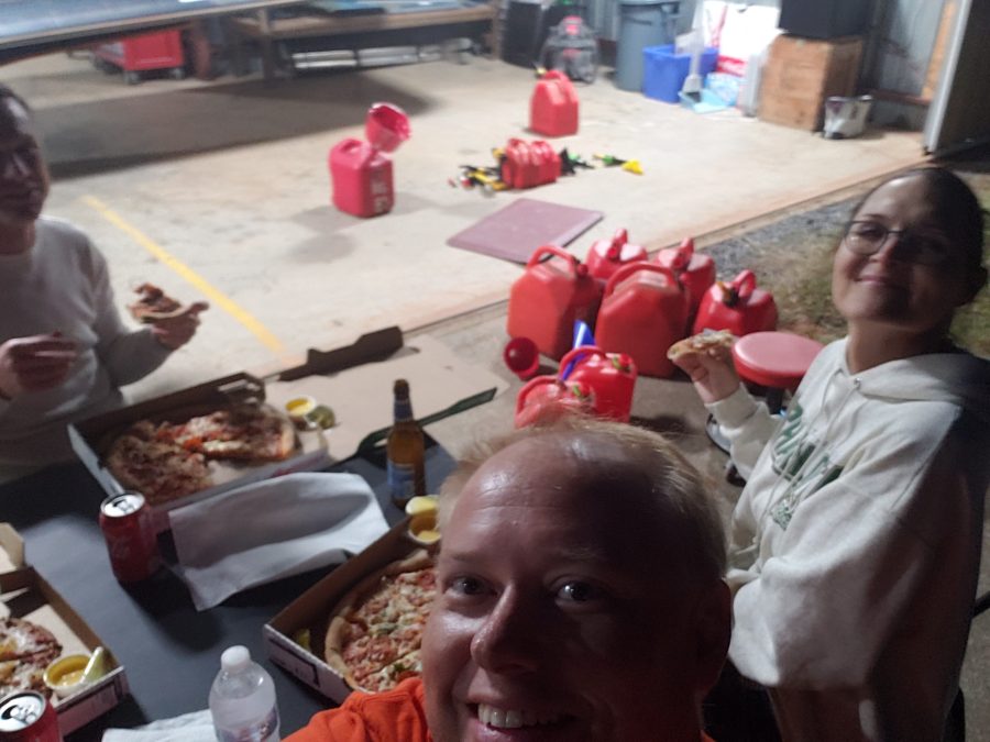
We started by filling the left tank at two gallon intervals and capturing the value on the avionics to create the level points.  The cans nor the amount in them were exactly precise, but it was close enough.  Parish and Jacquie came over and helped us with the reward of eating pizza on the ramp after filling the tanks.

We did 30 gallons in the left and then removed the sump drain to empty the tank and prepare for calibrating the right tank.  The right went pretty easy and we had no leaks on either tank!  I was nervous about leaks but the tanks held great.  Parish and I worked out a good technique of draining the fuel and switching gas cans.  Much easier with two people!

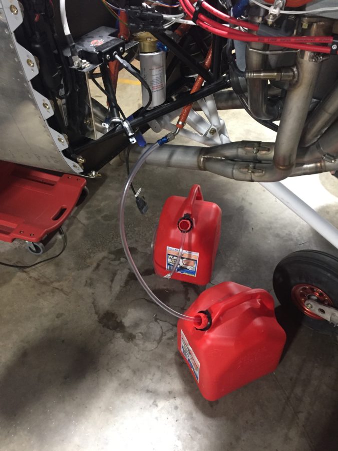
After the right tank was calibrated, I removed the return line from the firewall and put in an empty can to get ready for the flow and pressure test.  It took a few long seconds for the pump to purge air and draw fuel, but after what seemed like eternity, the noise changed and the pump got a hold of liquid.  Unfortunately, that liquid came spewing out of the firewall instead of the hose!  Turns out I mixed the fuel supply line and return line on the tunnel side of the firewall.  That caused a big oh shit moment!

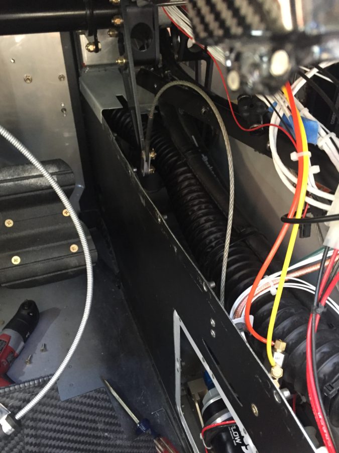
A bit of head scratching and cussing lead to digging in the already disassembled tunnel even more to get at the firewall.  Folks, not an easy task.  Two extensions, crowsfoot, and a lot of scratches, but I was able to get the lines un-crossed and hooked up on the tunnel side correctly.  

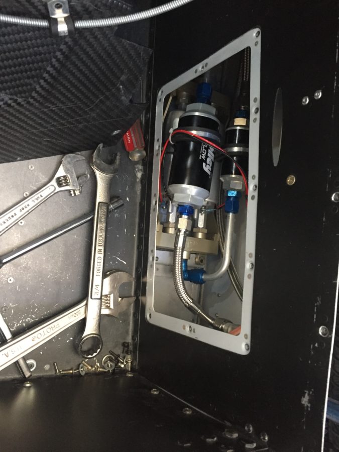
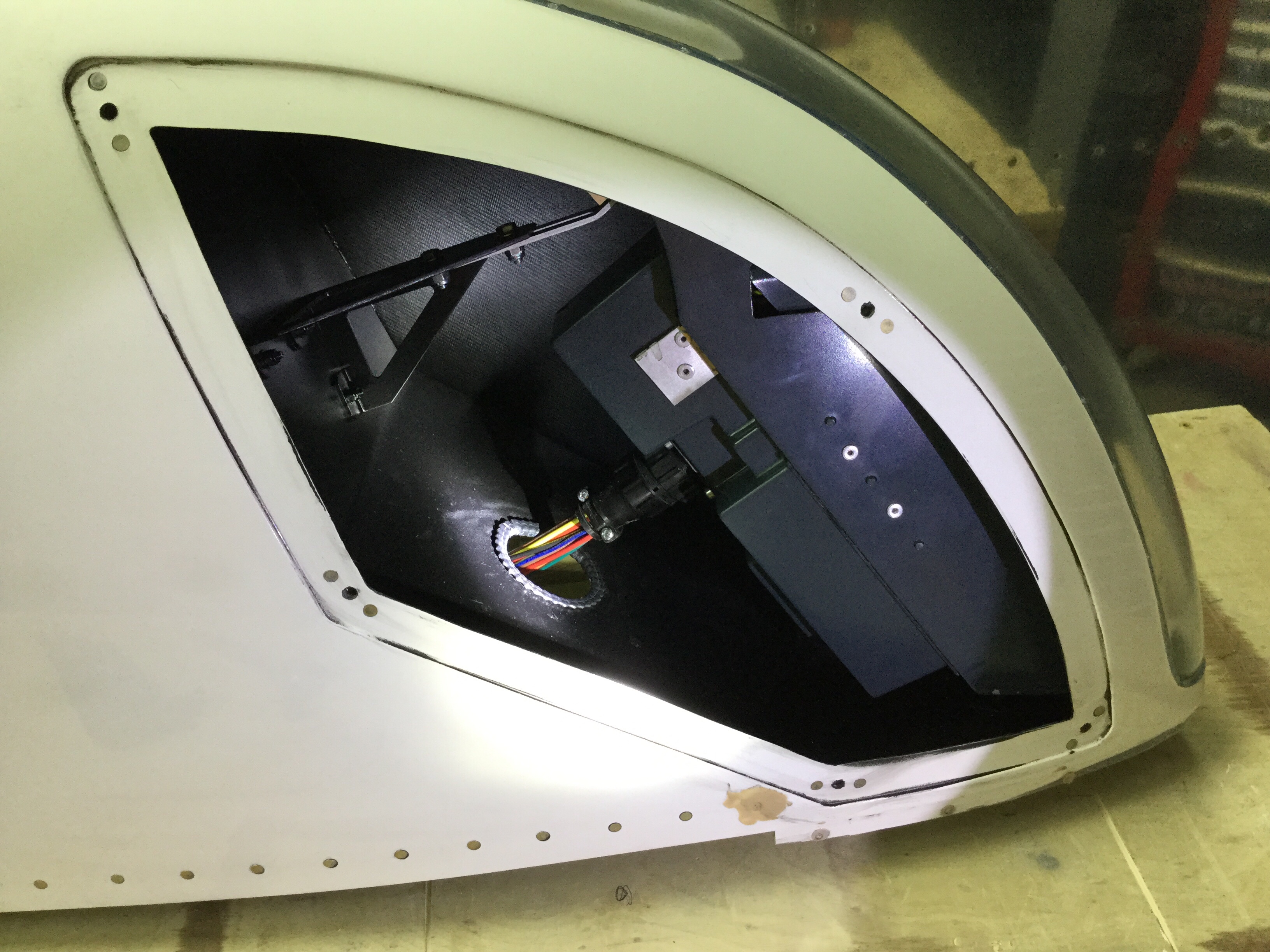
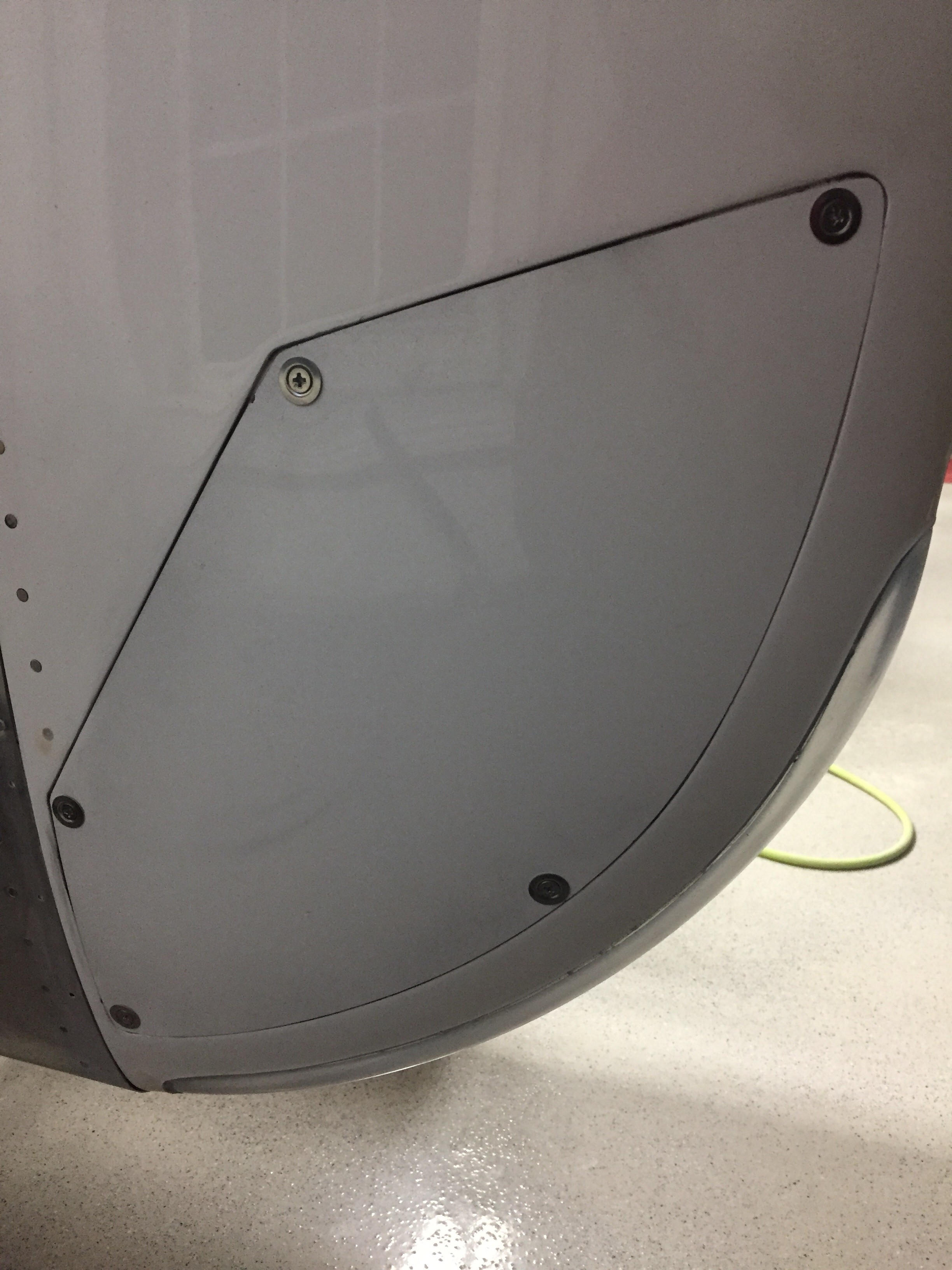
We flipped the fuel pump on again and had fuel coming out of the correct line.  We also had fuel coming out of the filter fittings.  Yup.  So, back in the tunnel I go.  Like an idiot, I didn’t use fuel lube (EZ Turn) on the AN NPT fittings into the fuel pumps.  I did for the fuel pumps manifold, but not the filters.  Gah, idiot.  So I had to take the whole fuel pump/filter module out and get at it on the bench.  While it’s not impossible, it’s not easy.  I’m definitely putting another tunnel access panel on the copilot’s side during the first annual.

Fittings were properly lubed and torqued, so the module went back in and we turned the pump on for a third try.  That was the ticket, as we got good pressure readings and good flow.  I turned the pressure up a bit to 45 PSI on the regulator and we did flow tests equaling 45 GPH on a single pump and 75 GPH with both on.  Plenty of fuel to feed the thirsty engine on take off!

Tess had one more surprise for me, though, when I attached the return line back to the firewall and found one more leak, this time at the outlet of the pressure regulator.  Seems that I didn’t torque that line at all.  Oops.  Again, this is why you extensively ground test!  Got that one all fixed and ran the pumps for about 30 minutes, just recirculating fuel with no issues.  She’s ready for engine start!

Back to my roots

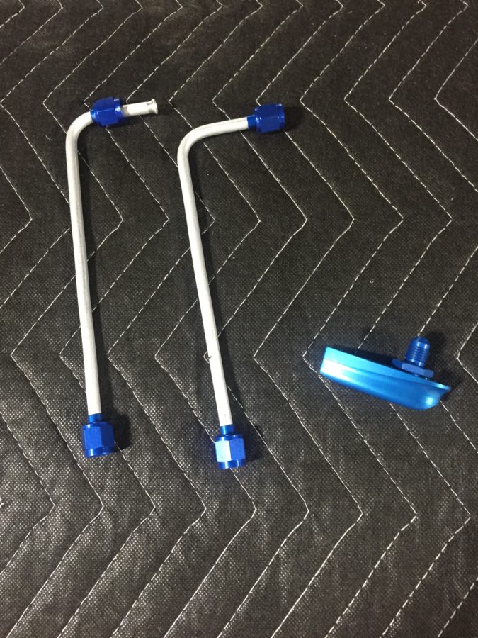
The wings are initially fitted to get the wing root covers installed and hook up fuel lines, vent lines, while getting the flight controls initially rigged.  The wing root cover brackets went on quickly and I fabricated the two fuel vent lines that exit the bottom of the wing root cover.

You also drill the bolt hole in the rear spar and work out a few other fasteners.  I installed the flight controls and worked out the stick to the plans while adjusting the rigging and pushrods.  It wasn’t too bad of a process with a little patience and double thinking before adjusting a rod end the wrong way!  In an afternoon, I had all the controls lined up nicely with the wingtips and fuselage just as described in the plans.

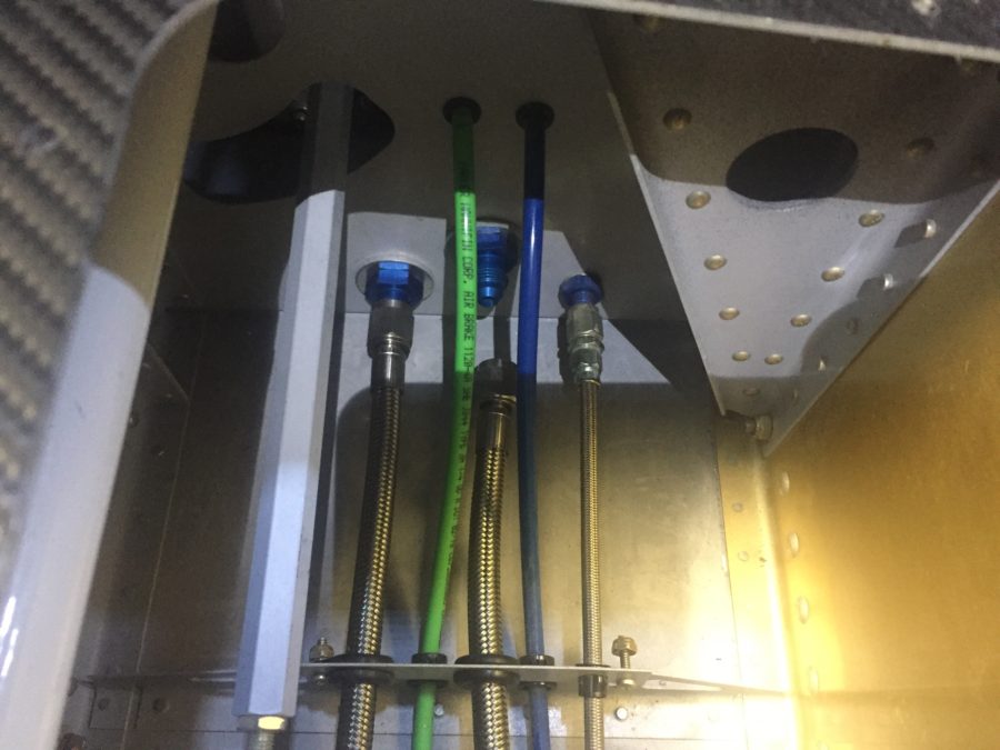
I also finished up the fluid lines up front.  TS Flightlines really came through again on an awesome product.  I had one line that didn’t quite fit to standards and the return lines for the fuel tanks from the tunnel had the wrong fitting (my fault) on them, so those went back for modification.  If you don’t know, TS will rebuild the lines for free until they are correct.  You get what you pay for and I’m glad I spent the money knowing I’ll have lifetime quality hoses.

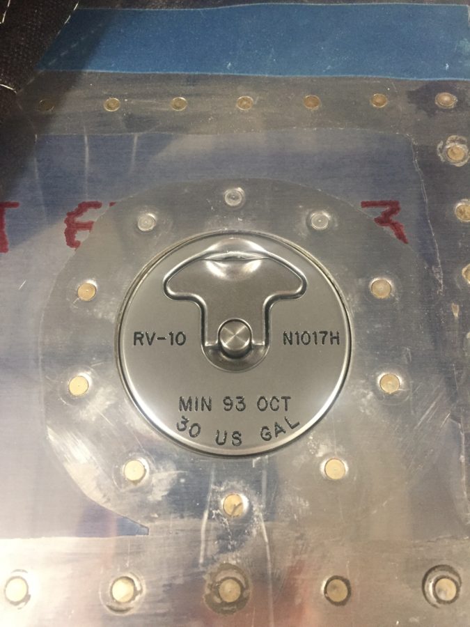
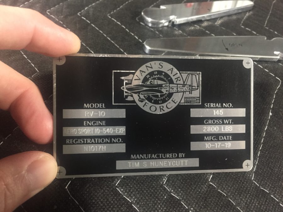
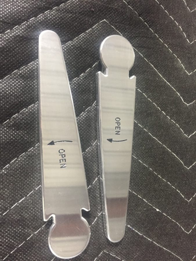
On a side note, my engraved parts came back looking fan freaking tastic.  The door handles are an extra set that I had and will go on after paint.  The data plate turned out perfect, as did the fuel caps..

Speaking of fuel, a while back I misdrilled the holes in the tunnel on the right side for the fuel line.  I decided at that time to just use a 90* elbow but that made torquing and replacing the incorrect fuel line difficult to say the least.  So I broke down and ordered 90* bulkhead fittings to do it correctly.  I had to dig into the tunnel to put the proper spacers (covering up the now too large hole) and secure the lines from the fitting to the fuel valve.  Boy am I glad I did this, because while looking around since I was in there, I discovered a cross threaded line on the fuel valve that would have made a mess come testing time.  I was able to clean the threads on the fitting and got it on correctly.  I took my time to reinspect all other fittings and lines.

With the airworthiness inspection scheduled for early November, I am shifting into inspection mode so try to check everything I can while working in an area.  It just so happens that the 137 articles Vic Syracuse has written for KitPlanes all mention loose jam nuts!  I want to break that chain but came close to being a statistic in your next bathroom reading material.  The left aileron jam nut had just enough space that it caught my eye while working the fuel lines.  Ha!  Not today, Vic, not today!

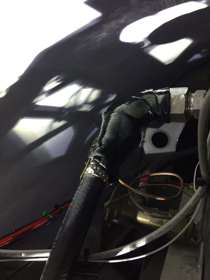
Another little side job that had been lingering was wrapping the aircon line with insulated tape to ensure the thermostat coil was in good contact with the line.  I had ordered this sticky tape months ago and finally crawled into the baggage area to finish that up.

Finally, Laura came over to help me pull the wings off so we could prep and install the wing root brackets and finish up the few tasks before permanent install.  This coming weekend will be critical for staying on track towards inspection, as I need to get the entire tail surface wrapped up and the fairings done.  Fingers crossed!

I give you wings, Red Bull gives you diabetes

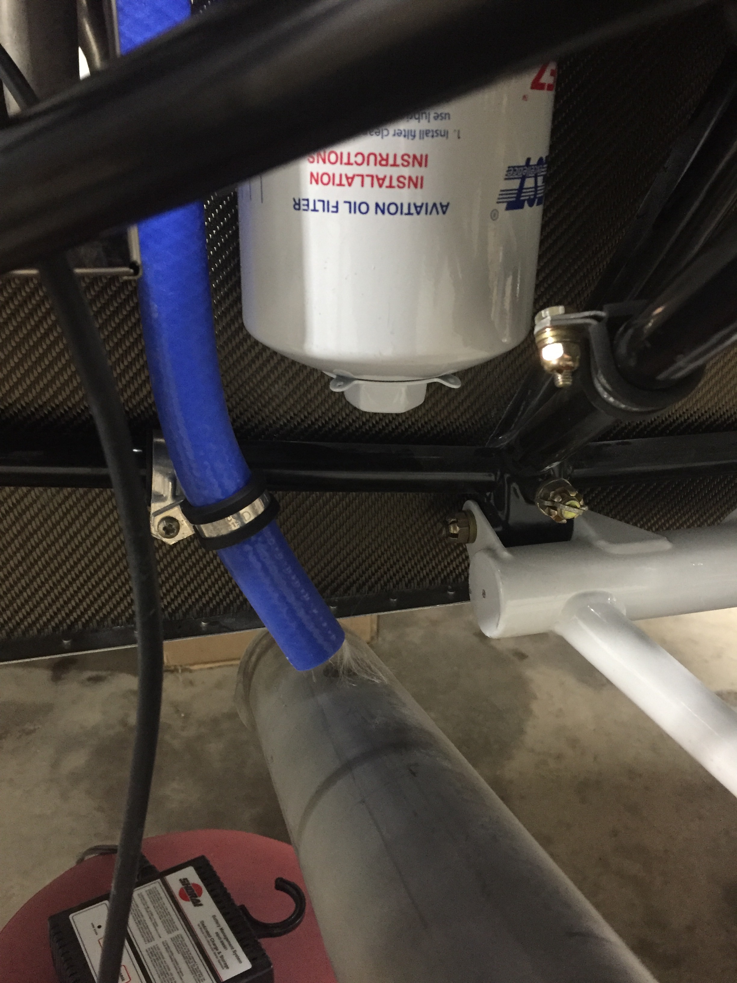
Before the wings go on, I finished up a few odd jobs since the parts came in from various suppliers.  I ordered enough hose to route from the air oil separator to the cowl exit and secured it in place.

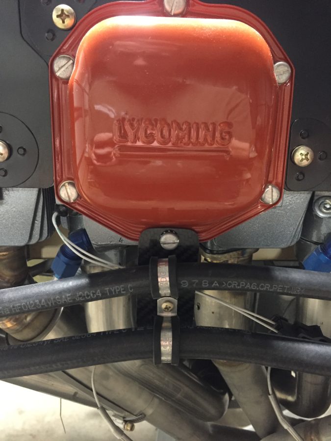
I also finished securing the air con hoses from the firewall to the compressor.  I made a bracket to hold hose clamps on the bottom of the valve cover and it keeps the hoses from flopping around the side of the engine.

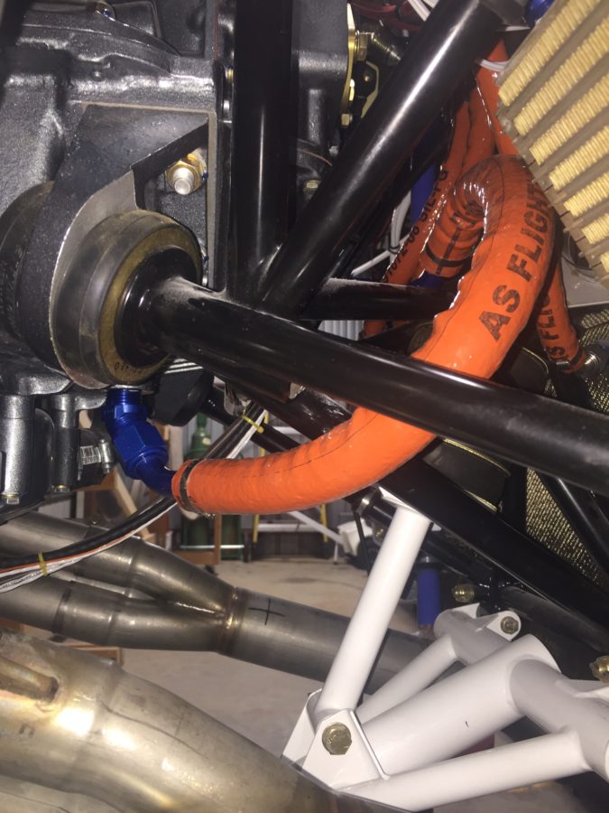
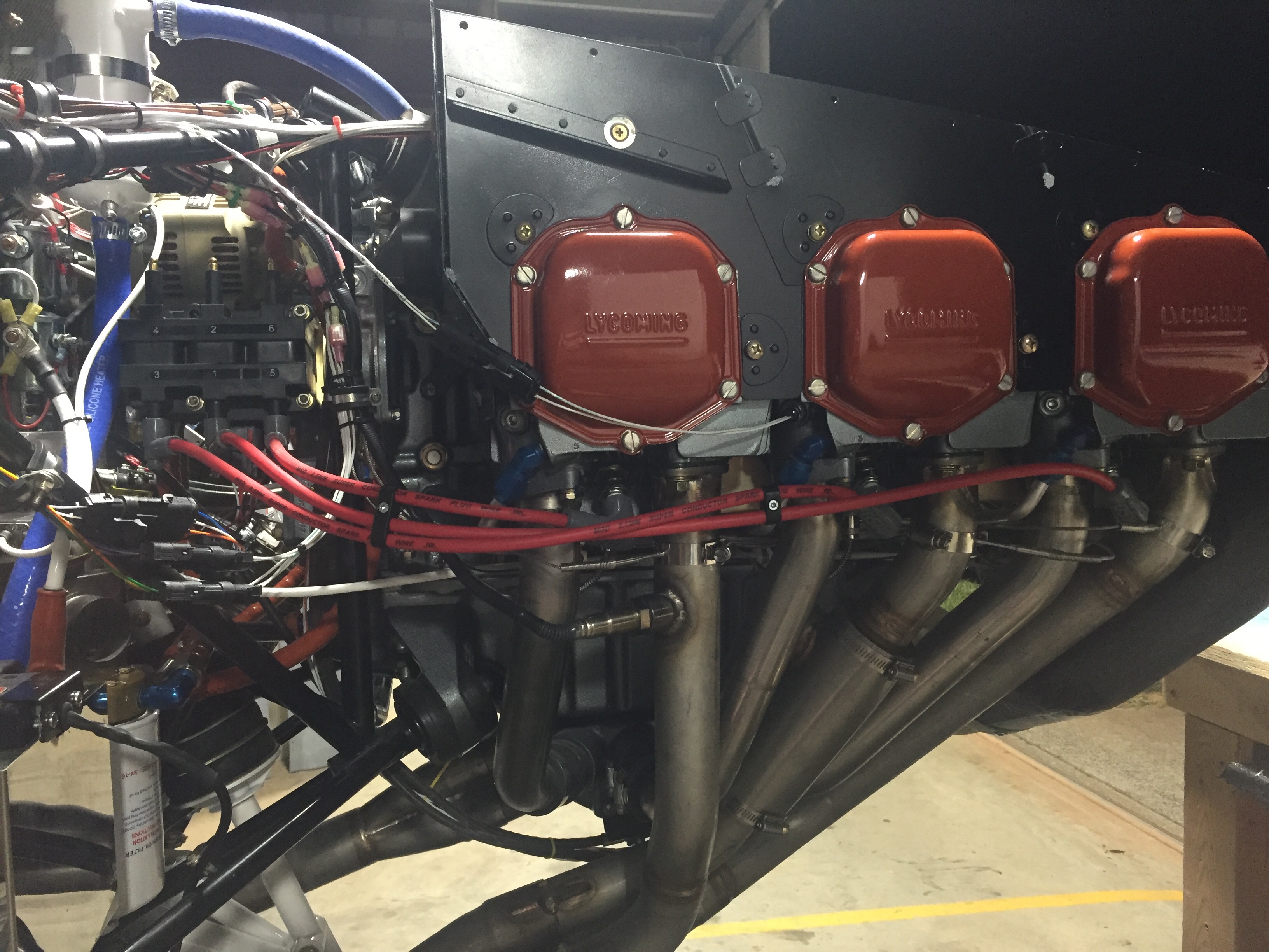
I also did something on the right side of the engine.  I don’t know what I did, but I took this picture which meant I did something over there.  I know I secured a few wires, added a ground from the engine to the mount (which I may have mentioned before, I don’t know), or maybe I just felt it looked pretty.  Either way, here’s the right side of the engine and the mass of wires; enjoy.

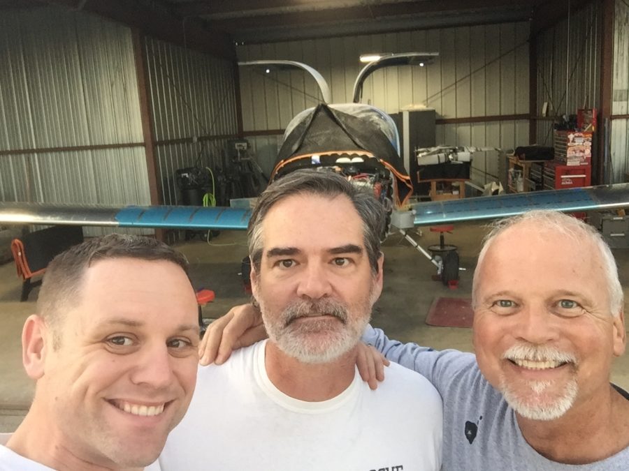
Tapping into my network of gulible aviators, I ropped two guys into helping me install the wings for the initial fit.  I must admit, I typically don’t read ahead more than a few steps in the plans so I was pretty dissapointed to find out the wings go on then have to come back off before getting bolted on for good.  It figures, though, you wind up doing everything twice on this airplane so why would the wings be any different?  We got a few sawhorses and a plan together and according to the time lapse video shown below, we installed the wings in about 27 seconds!

Really, they went on a lot easier and smoother than I expected.  I ordered new nuts for the wing attach bolts but will reuse the original bolts used during construction of the fuselage.  I did get the suggested hardware store bolts to align the wings initially and they worked very well.  I also felt better seeing the good fit between spar components, as I had a scary moment a few years ago when I realized my spacers weren’t the proper combination even though the dimensions worked out in the end.  Either way, everything fit snug and as it should, so all is good.  Great job Steve, smile for the camera.  Or not.

It’s pretty bad ass to see wings on the plane after 6 years of telling everyone you’re building a plane but it actually looks like an enclosed canoe.  So I decided to have a bit of fun and hook up the ZipTip lights.  Combined with the gull door lights, it looks like a space ship!

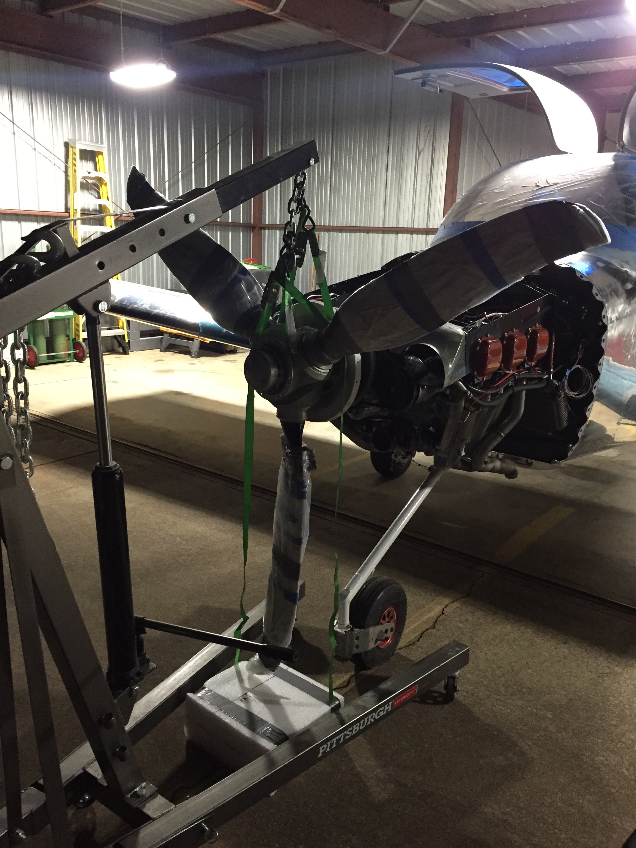
The evening was getting late, but the big triangle box was too tempting for me so I pressed on with hanging the prop.  Following the manual, I inspected and oiled the critical o-ring on the hub and ensured no damage as it slid on the prop flange.  Again the engine hoist came in handy as I secured the prop to the hoist and used it to lift in place without asking for a third back surgery.

The bolts for the propeller are rediculously stupid and hard to get to.  Once I got each one threaded, a challenge in itself, they can each be turned about one revolution at a time before all the others have to be tightened in sequence.  There just isn’t much room and you want the prop to go on evenly.  An hour later, I had the bolts hand tight and the prop was on.

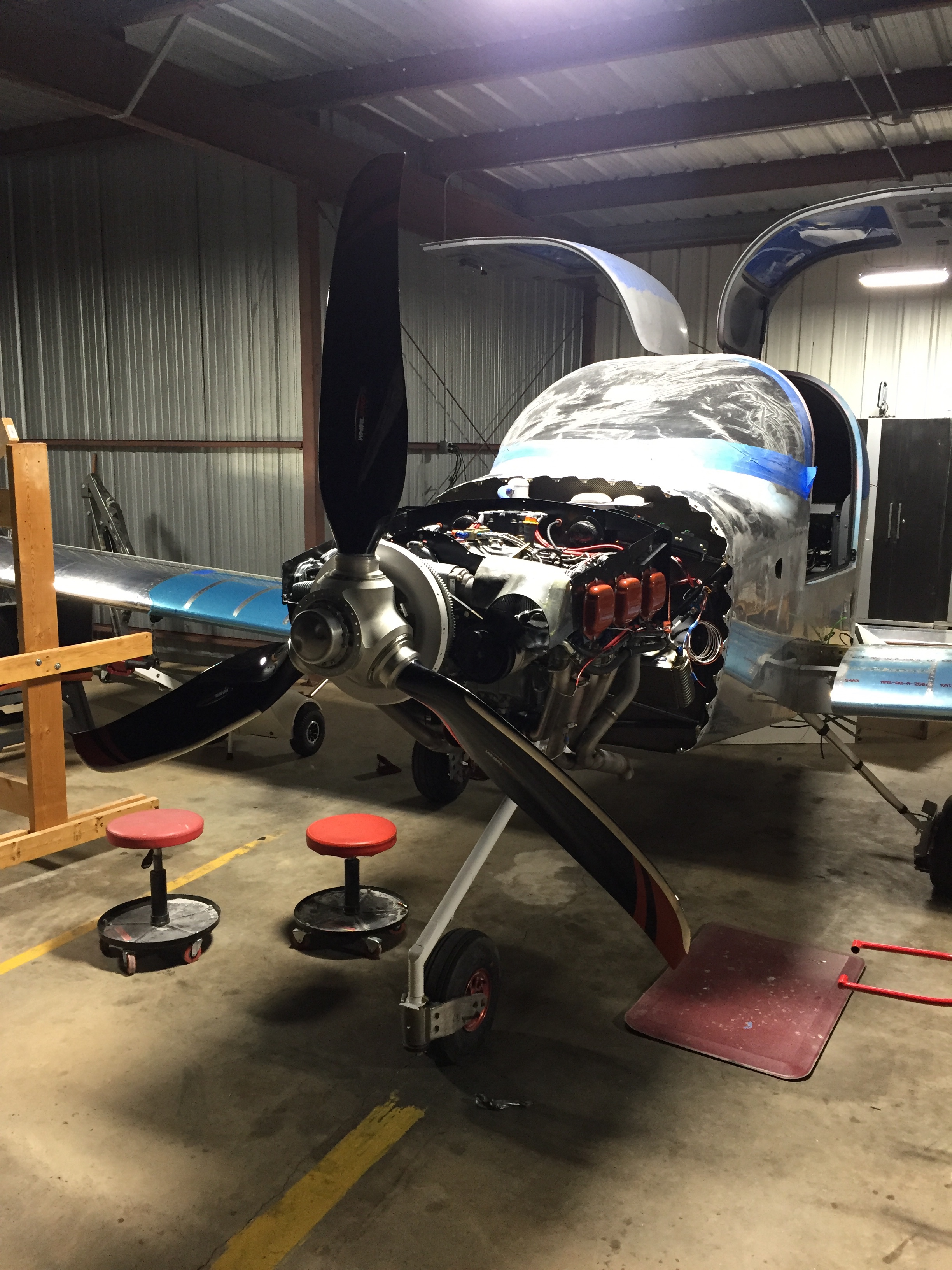
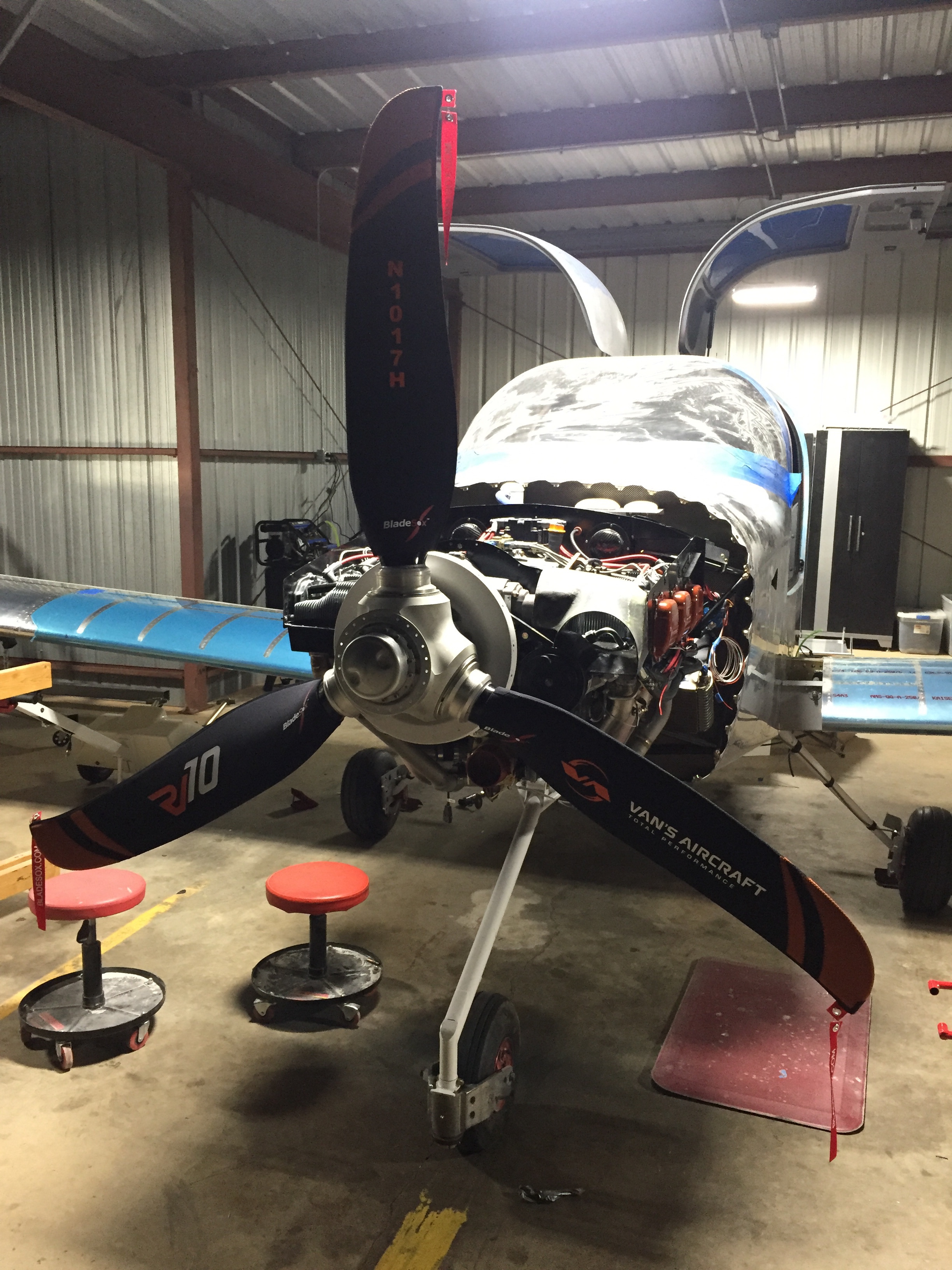
I realized quickly by my goose bumps and those on the propeller blades that it was chilly, so I went and got some socks for her.  David makes these as a business (search BladeSox on Facebook) and they are just the bee’s knees.  I don’t care if they make me a super dork.  I had him do the tail number, Van’s new logo, and the best – our RV10 logo created by Sam at Plane Schemers.

It’s really starting to look like a plane now!

Wired for moving day

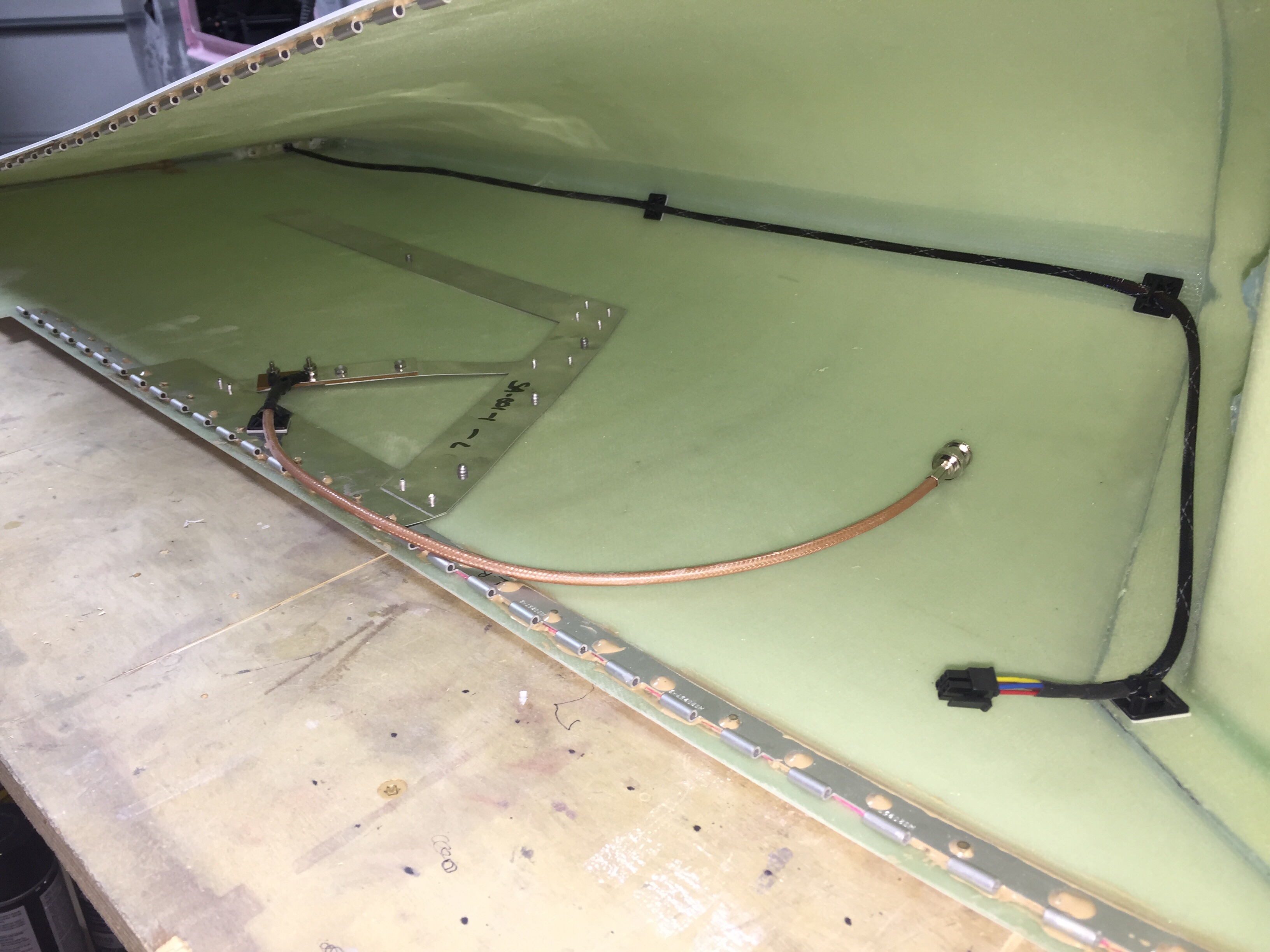
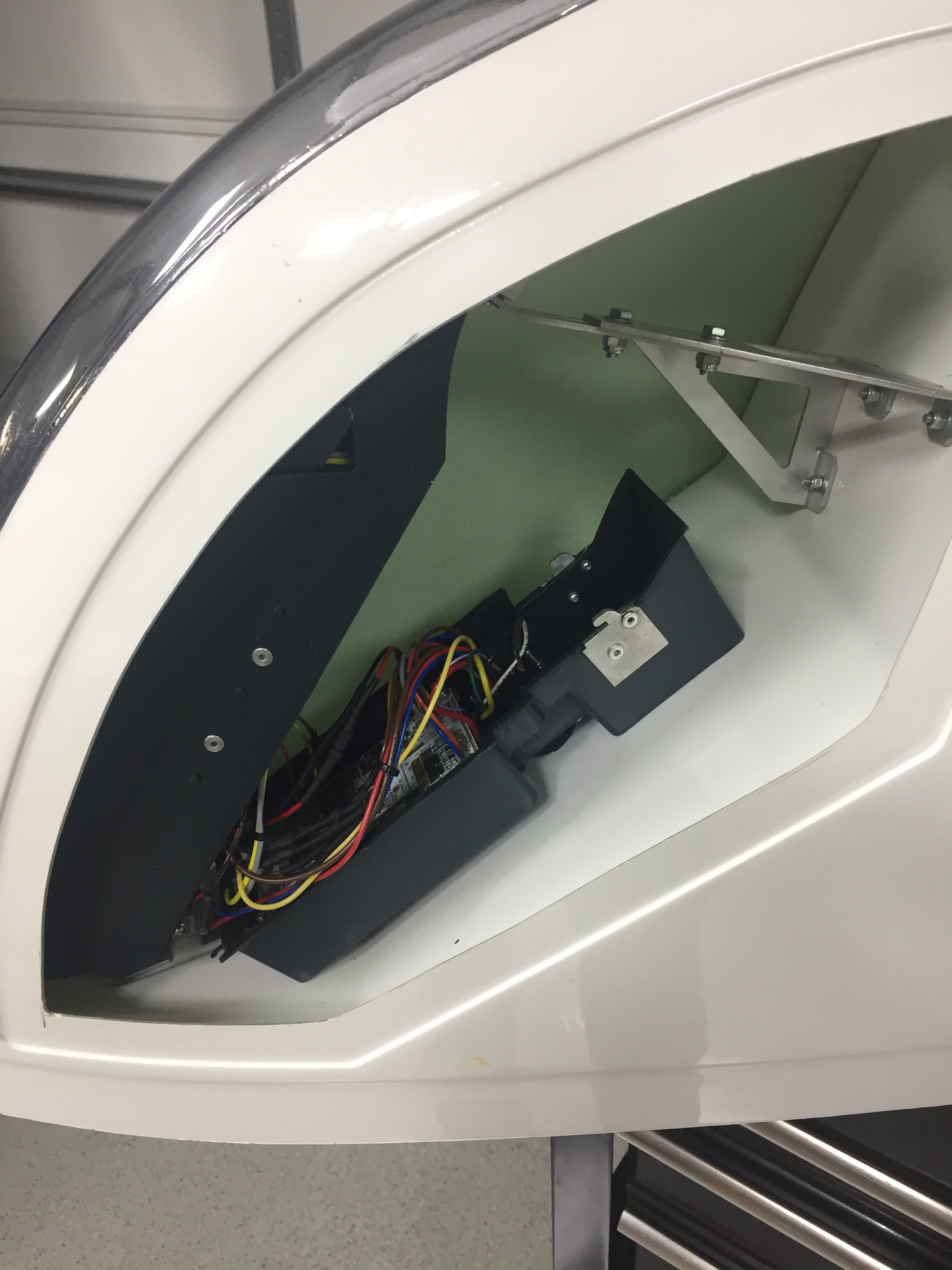
With the tips fitted to the wings, it’s time to run some wiring and finish up the wings. I integrated the Archer nav antenna into the tip mounting hinge which thus links the antenna to the wing for a proper ground plane, per the plans. I used a few pop rivets through the bottom of the tip to secure the antenna in place. I wanted to make the tips easy to remove, so I used bulkhead BNC fittings for the coax on both end of the wings.

I also ran the wires from the trailing edge position / strobe light up towards the main lighting modules and installed a micro fit connector so that the lighting module can be removed for future maintenance / replacement should the need arise. Again, all of the wiring has been documented in Visio including pin outs on each connector so I’ll be able to reference it long after I’ve forgotten how or why I did it this way!

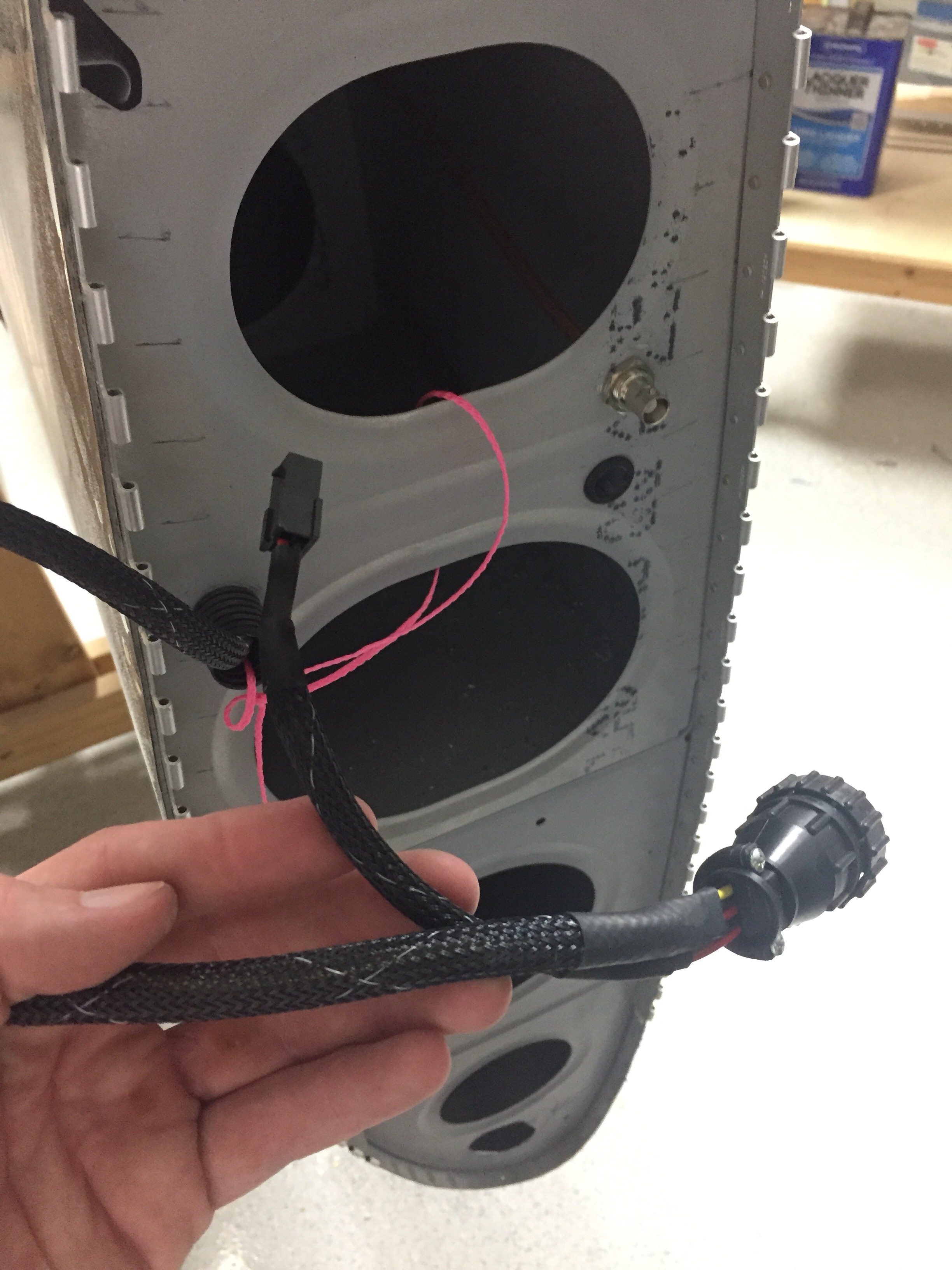
I used CPCs for the main wiring runs and am very pleased with the setup. Some folks avoid connectors like the plague, but I don’t see them as failure points if they are done right and properly tested / treated. I checked continuity of each wire after running them all so I know everything is ready for plug and play. The wing root connectors include those for the pitot heat and AP servo on their respective wings. The aileron trim servo is on it’s own micro fit connector due to the small wire size. I’ve gotten really proficient at the micro Molex connectors and really like them.

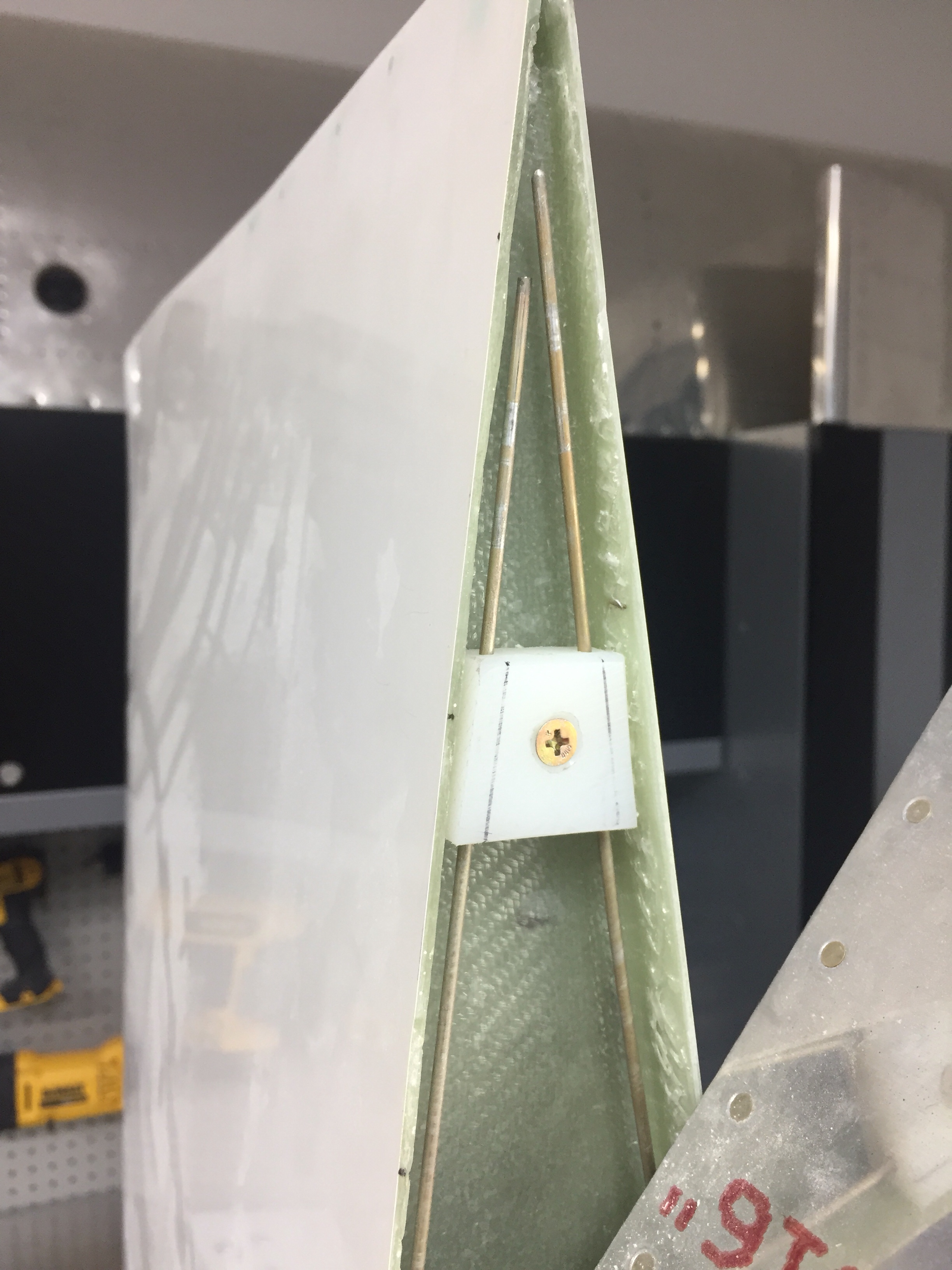
I also had to layup a small rib on the trailing edge to not only support the shape of the tip, but also provide a mounting surface for the hinge pin retainer. I used a trimmed block of delrin and nutplate to secure the pins. This keeps the pins inside the tip profile and thus unable to work themselves loose. They also butt up against a stop on the leading edge. I didn’t want to put a bend in them, as it’s very easy to use a drill and spin them in / out.

The only system component not installed in the wing is the OAT sensor which I’ll get with the avionics in a few months. That’ll be simple to put into an access plate and a string is still waiting to pull wires through the wing root.

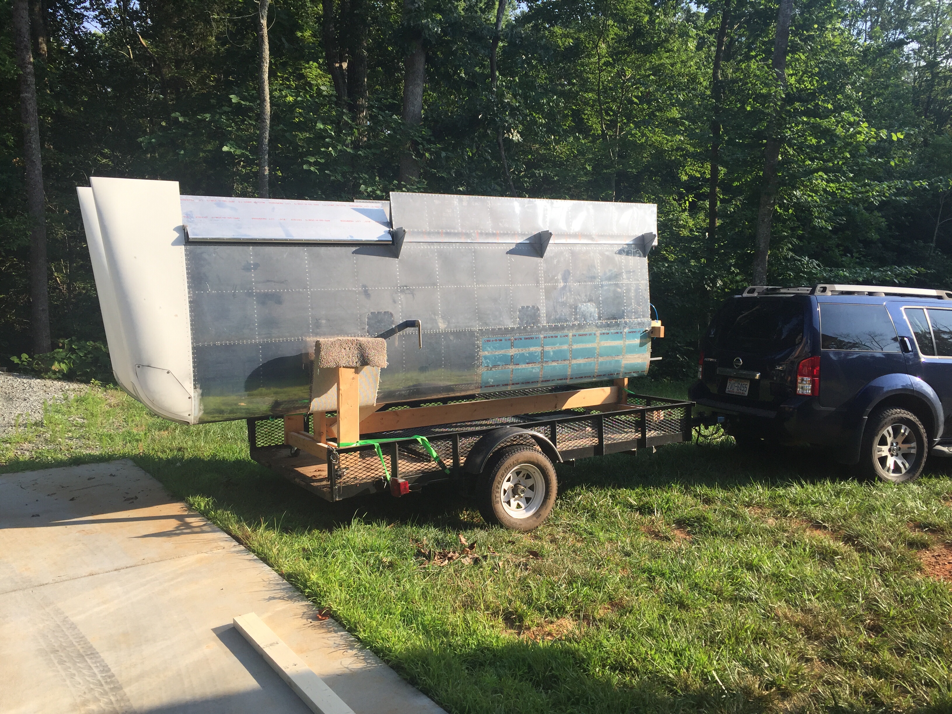
Since the wings are all complete, I need to get them out of the garage to make way for the finish kit and make me feel like I have real airplane parts in a hangar. My Diamond bros graciously offered a corner of their hangar for me to store the wings in until our hangar is available. So moving day came and anticlimactically went! It was like I designed the wing rack for the trailer and with Ron’s help, they rolled right on and off. We used a few tie downs and took our time on the 10 minute drive to the airport with no damage reported. I hope the fuselage move goes this smoothly!

Bonnie the Bonanza is now babysitting RV wings. Meanwhile, back home the shop has so much room for activities such as finishing the cabin top and getting ready for the finish kit and cowling which are due to arrive early August.

Success hinges on the tips

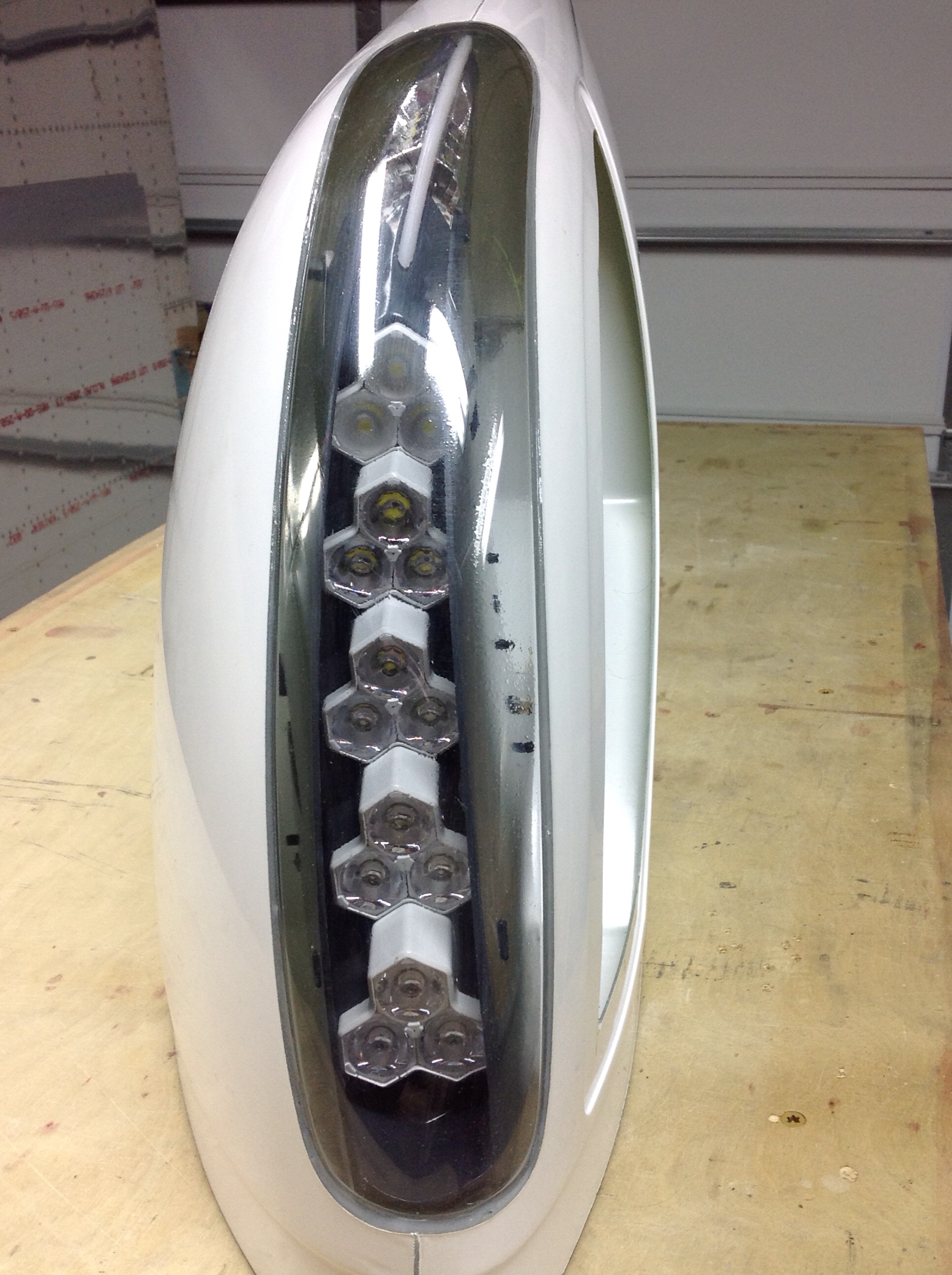
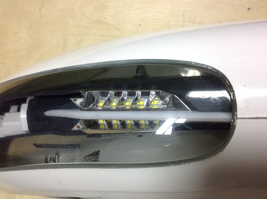
Some time ago, I received a large package from Aveo containing a brand new set of their ZipTips, wing tips with slick looking LED’s. I’ve been waiting on these things for years, ever since I saw them at Sun ‘N Fun in 2013. I’ve hounded poor Damien at Aveo relentlessly but it paid off with an opportunity to help them out with profile shaping and some prototype testing. In the end, I think it was worth the wait and I’m really looking forward to seeing these things all completed.

Now, because I was helping out, I received the prototype of the light modules and to say it nicely, they’ve been through a tough time. Unpacking the box, there were a few things rattling around and the back of the light module had come off.

First order of business was to test out the light modules. There is a 16 pin CPC with pigtails included, but the wires weren’t pinned out accurately causing me a few scares that I had shorted out the board or LEDs. After a few emails and testing, I was able to re-pin and document the proper wiring schematic. I did this for both sides and then took the time to re-seal the modules closed using some silicone and fresh hardware.

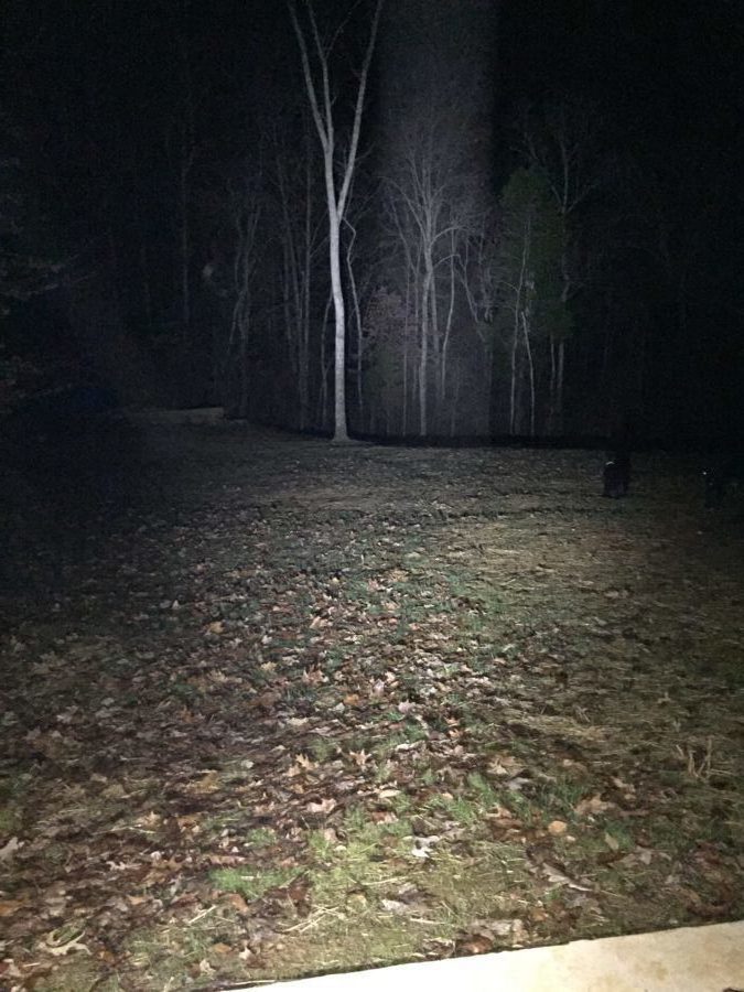
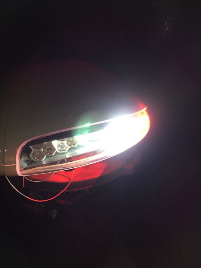
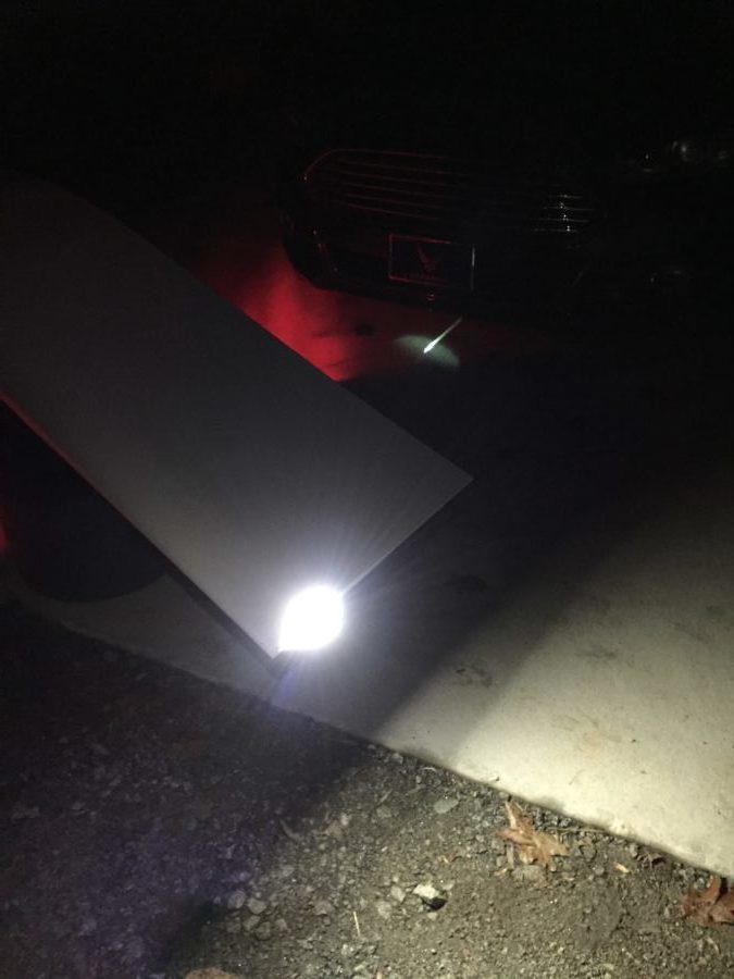
As others have said, these things are crazy bright! I hooked them up outside just to see what could be lit up and man, I am really impressed. Pictures and video don’t really do justice, but let’s say that I’ve flown many Pipers and Cessnas that have less than half of even one of these landing lights. Combined with the Aerosport taxi light, I think I’ll be able to light up the night just fine.

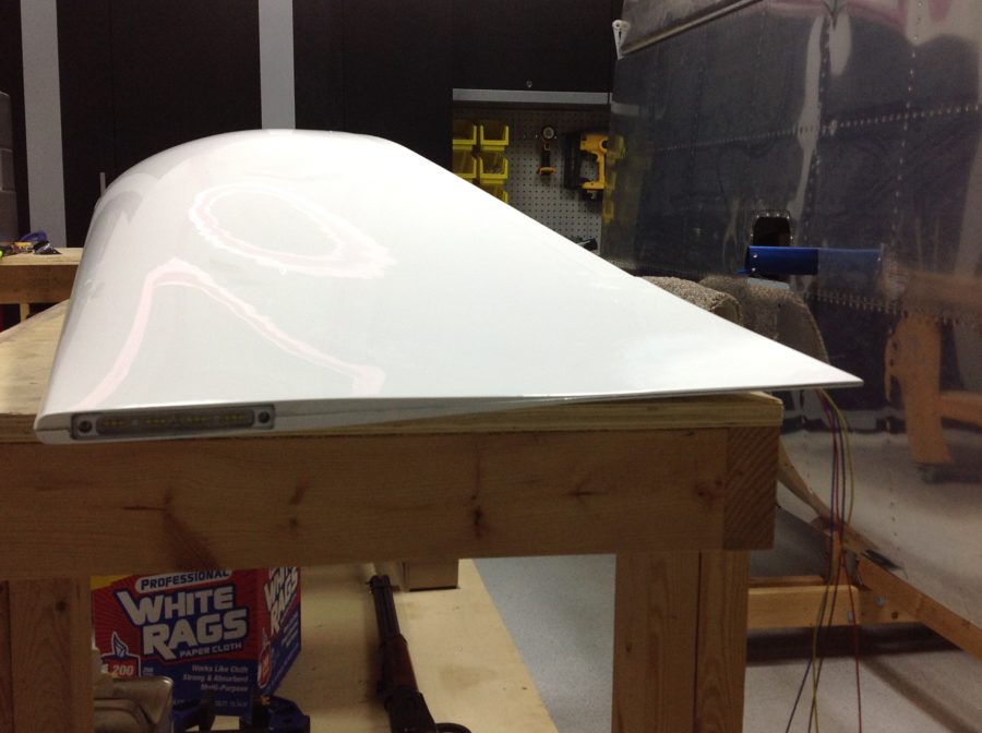
After testing, I started to do a rough fit and trim, but then they got put to the side waiting on the piano hinges that I planned to use to mount them. A year later, it’s time to finish them up so that I can call the wings complete. The first step was to complete the trim using the methods followed by others to install the tips with hidden piano hinges instead of screws and nut plates. I won’t go into detail as it’s documented on plenty of other build logs and forums out there such as VAF. Taking my time, I was able to get a really nice fit and used the cut off wheel on a die grinder just as I did with the cabin top.

I did run into some interference with the light module mounting hardware that butted up against the end rib. After talking to Van’s support, I drilled an accommodating hole in the rib to allow the hardware to protrude inward through the rib and let the tip sit flush against the skin. Once I had the hinges on, I split the trailing edge to reposition and line up with the ailerons. This is a common practice, even on the stock tips and was fairly straightforward. After a bit of work, I had a nice straight line from flap to tip.

Finally, I received some stainless steel hardware in for the light module access covers and mounted them with nutplates. Others have used a lot more fasteners than I did, and I’ll probably go back and add a few more before first flight. I painted the inside of the light area black to give the lights a meaner and cleaner look. I also painted the outside of the light reflectors, again, just for cosmetic purposes. Next up will be to run the wiring through the wings, mount the archer antenna, and make a pin retainer for the hinges.

Quit flapping around

One of the last projects before the cabin top section is the flap torque tubes and motor.  Switching gears back into progressively drilling holes in steel is a bit tough and time consuming.  Lots of oil, lots of shaving, and patience is needed.  I had to open up the holes with a deburr tool through the side panels which the tubes pass through.  All fairly straight forward, however, and everything lined up very well in the end.  The motor was an easy mount and at the end, I had to hook up a 9 volt battery to test it all out.  Pretty cool seeing systems start working in the airplane!

This was several evenings in the shop getting it all fabricated and I quickly realized that there is nothing left to do than put the cabin top on!  I also realized that while the cabin top is a massive amount of work, it’s also a good time to order the finish kit since having the doors is key to getting all the big work done on the fuselage.  I’m looking forward to getting the big pink thing down from the ceiling and on the fuselage!
Bite my shiny metal bottom…skin

After a visit from my EAA chapter tech counselor and a great report card, I was confident in buttoning up the wings with the bottom skins.  It takes a lot of clecos to position the skins and a lot of time spent drilling and deburring.  Then the dimpling fun begins and priming.  


The riveting process is another dreaded task, besides building the tanks.  You have to start with the rear spar and bend the skins up.  I used duct tape to help hold them in position and allowing me to rivet a few rivets at a time working from the rear down each rib.  


Overall, it really wasn’t bad.  I managed to get the entire skin done alone except for three rivets where my arms just weren’t long enough.  I had the wife man the gun for those on the j-channel.


On the left wing, I installed the pitot mount. I also got the aileron trim servo hooked up mechanically and electrically with a micro Molex connector.  I was worried that the springs on the setup would be a pain to install, but again, it wasn’t too bad.  No picture, as once the springs are on, the access panel goes on.

Finally, before replacing the aileron and flaps, I complied with the service bulletin regarding the aileron mounting bracket. Other builds have suffered cracking and the gap fairing must be cut back to allow inspections at regular intervals.  Replacing it is not recommended per Vans, as it can cause more damage trying to remove the rivets than replacing it.   A quick job with the Dremel tool.

Excuse me Sir, but your pitot is showing

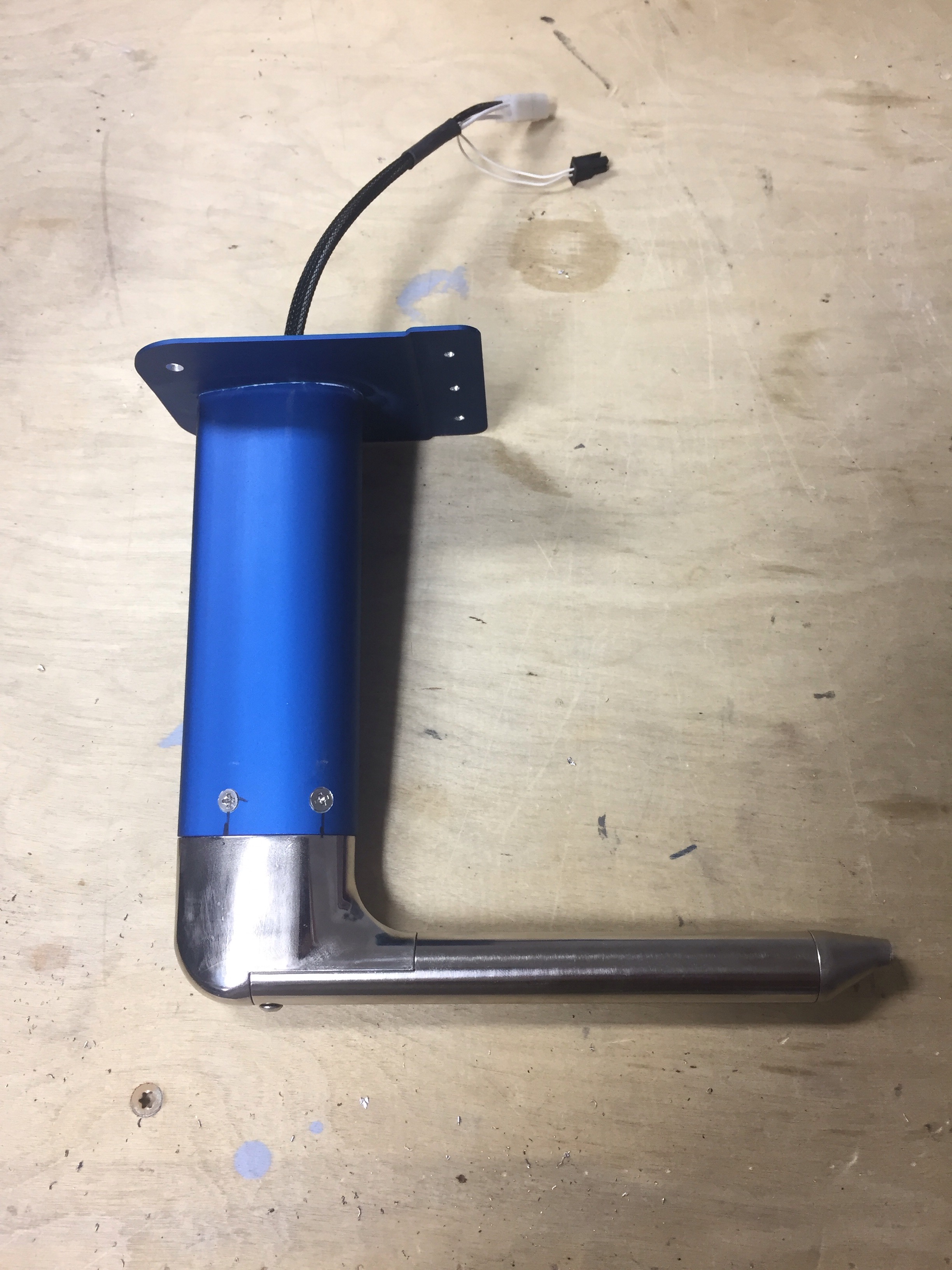
Turns out, the pitot is much easier to install before putting the bottom skins on.  I learned this thanks to the great info from other builders’ blogs.  Check out the link Other Build Logs for some of my go to’s.  It’s good advice, as it gave me a lot of room to mount the heater controller and the actual mount itself.

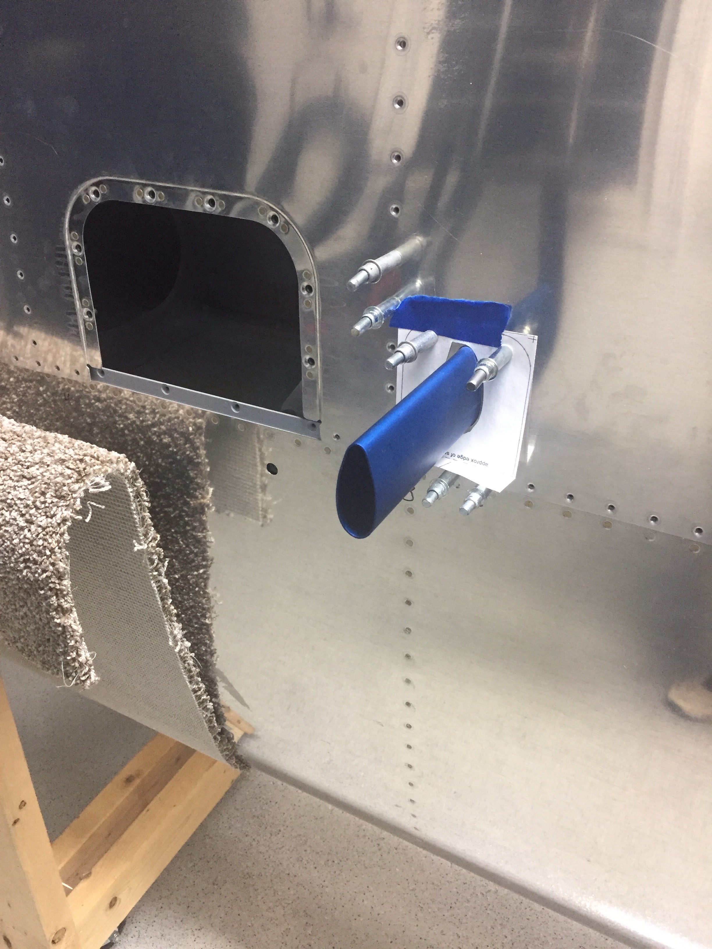
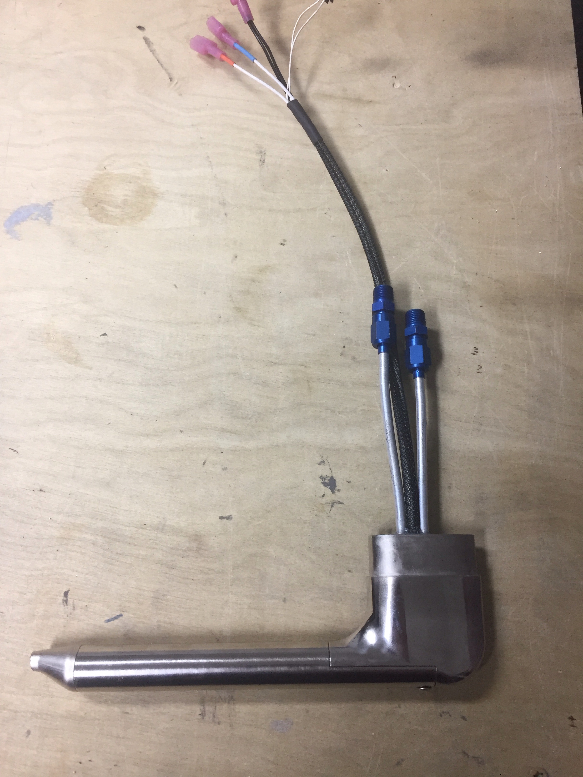
I’m putting in the Dynon heated AOA and pitot tube along with the Safe Air mount.  Great products all around and the process wasn’t too bad.  First step is marking and cutting the hole in the skin.  Safe Air provides a nice template for this and a Dremel makes quick work of the task.  I chose to use the standard Van’s location just inboard of the tie down location.


I used a bottoming tap to carefully cut threads in the pitot tube, making sure the drill and tap stayed clear of the tubes.  I also installed the fittings which allowed me to use the new crows foot wrenches.  It did surprise me how much torque they require, as I was afraid of ruining them.  But they shouldn’t leak now that they are good and tight per the specs.


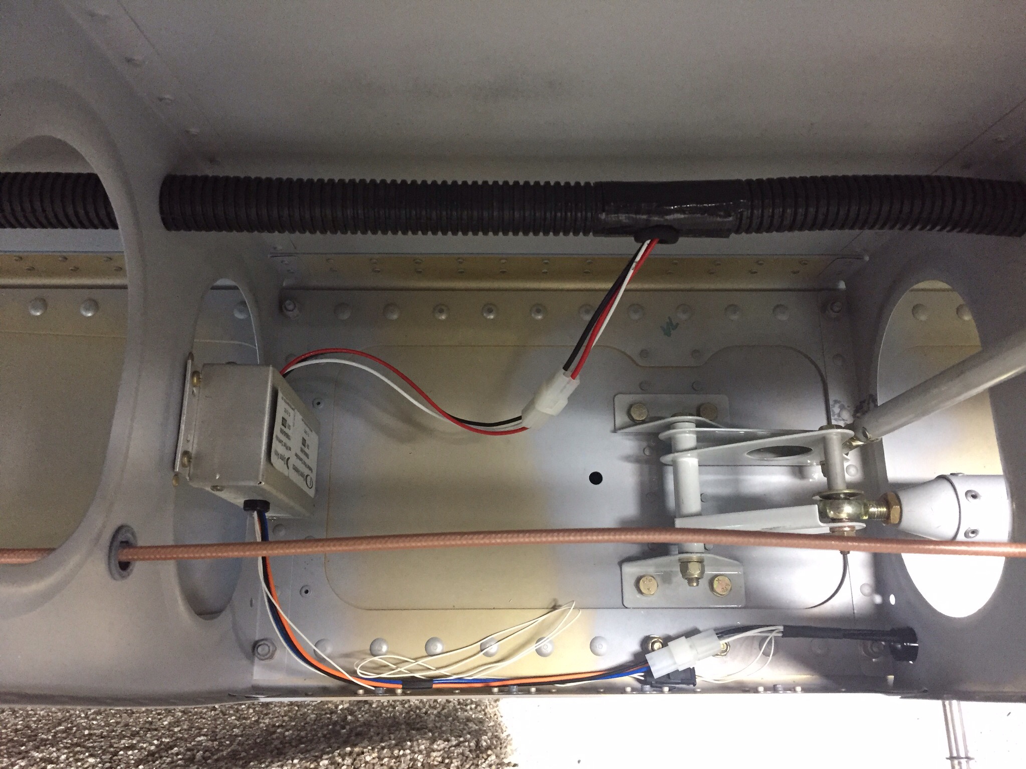
I also got to break out my Stein wiring kit for a connector and pins.  I’ve used a similar crimper before, so the hardest part was figuring out which pins went into which side of the connector.  I shortened the wires to reduce the amount of slack wiring inside the wing and put the pins on with ease.  The only thing left to clean up is putting some braided sleeve on the wires to provide some abrasion resistance and spruce them up a bit.


One piece of advice is to mark the wires coming from the pitot itself before cutting off the spade connectors.  There is a blue and orange connection from the controller but both wires from the pitot are white with a corresponding piece of heat shrink on them.  I had to email Dynon and get a trick to identify which wire went to blue / orange.  They advised a great trick to freeze the pitot and determine which is blue / orange by seeing which side of the tube heated up first.

I originally mounted the controller to the access panel as others have done, but didn’t like that with having to tuck wires in so I decided to follow another builders idea of putting it on a rib.  Adding four nut plates makes it a clean instal and still allows easy to access once the bottom skin is on.  Overall, I’m very pleased with the install and looking forward to having the integrated AOA display in the cockpit.