Are you a bit warm? Turn on the A/C

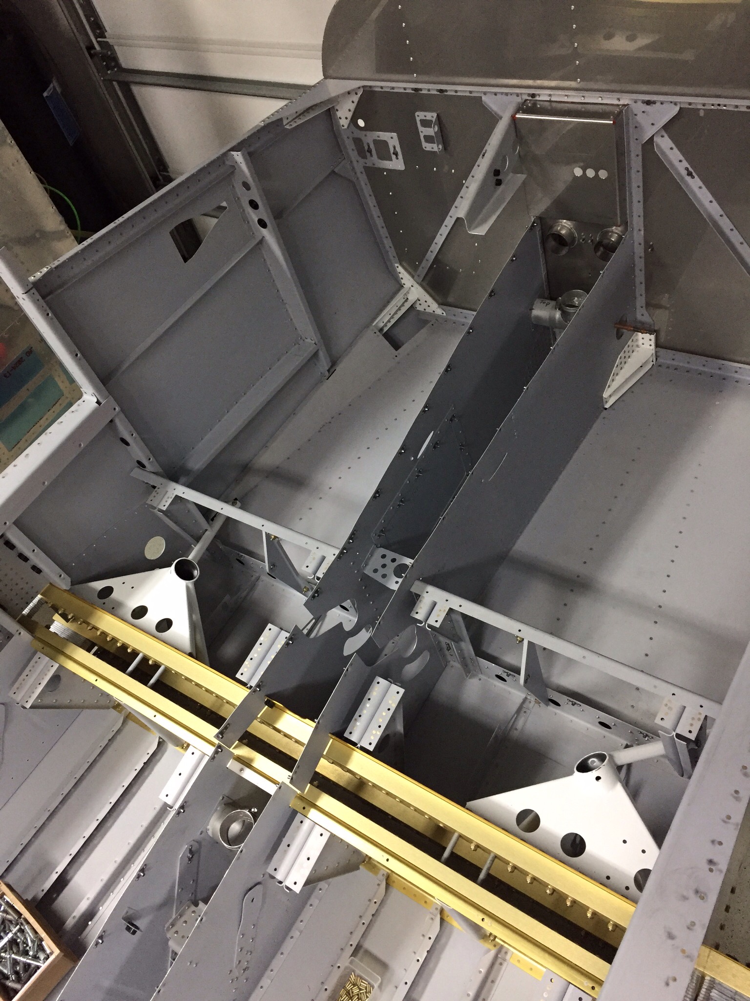
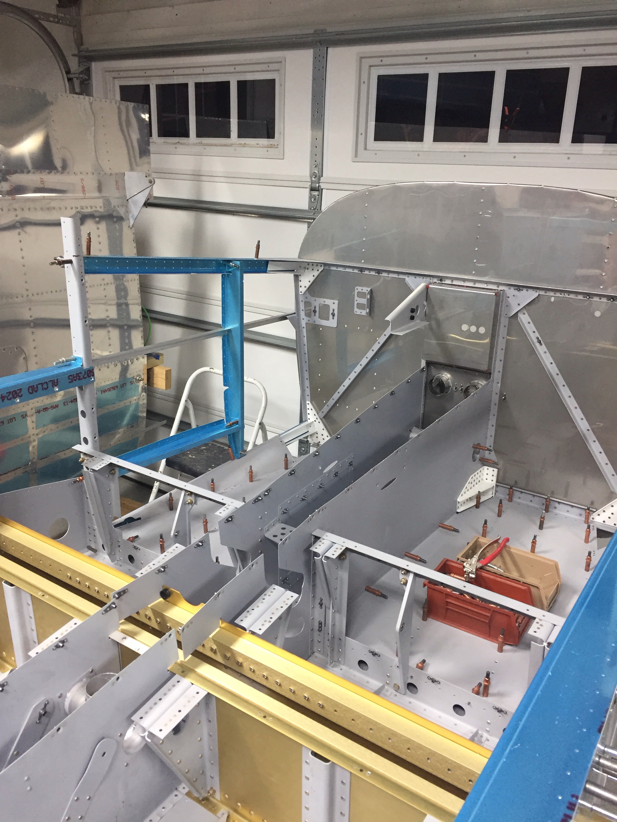
With the tail cone attached, I wanted to get the Flightline A/C system installed before too much else gets put in which would make access difficult. The majority of the system is located behind the baggage bulkhead, so it’s easy to get to right now. The first step is to mount the condenser tray onto the longerons which is simple enough. I spent some time cleaning the air handler up and getting all the old dust off of it. I also cleaned up the insulation a bit and used foil HVAC tape to seal the remaining uninsulated areas. I fixed a couple of nasty looking nutplate rivets on the tray as well before putting it in the airframe.
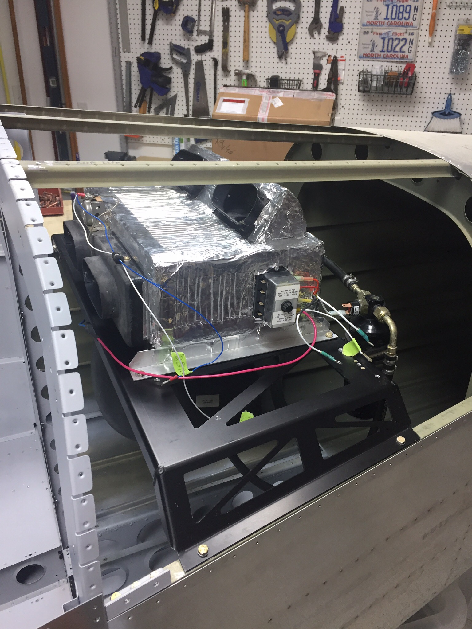
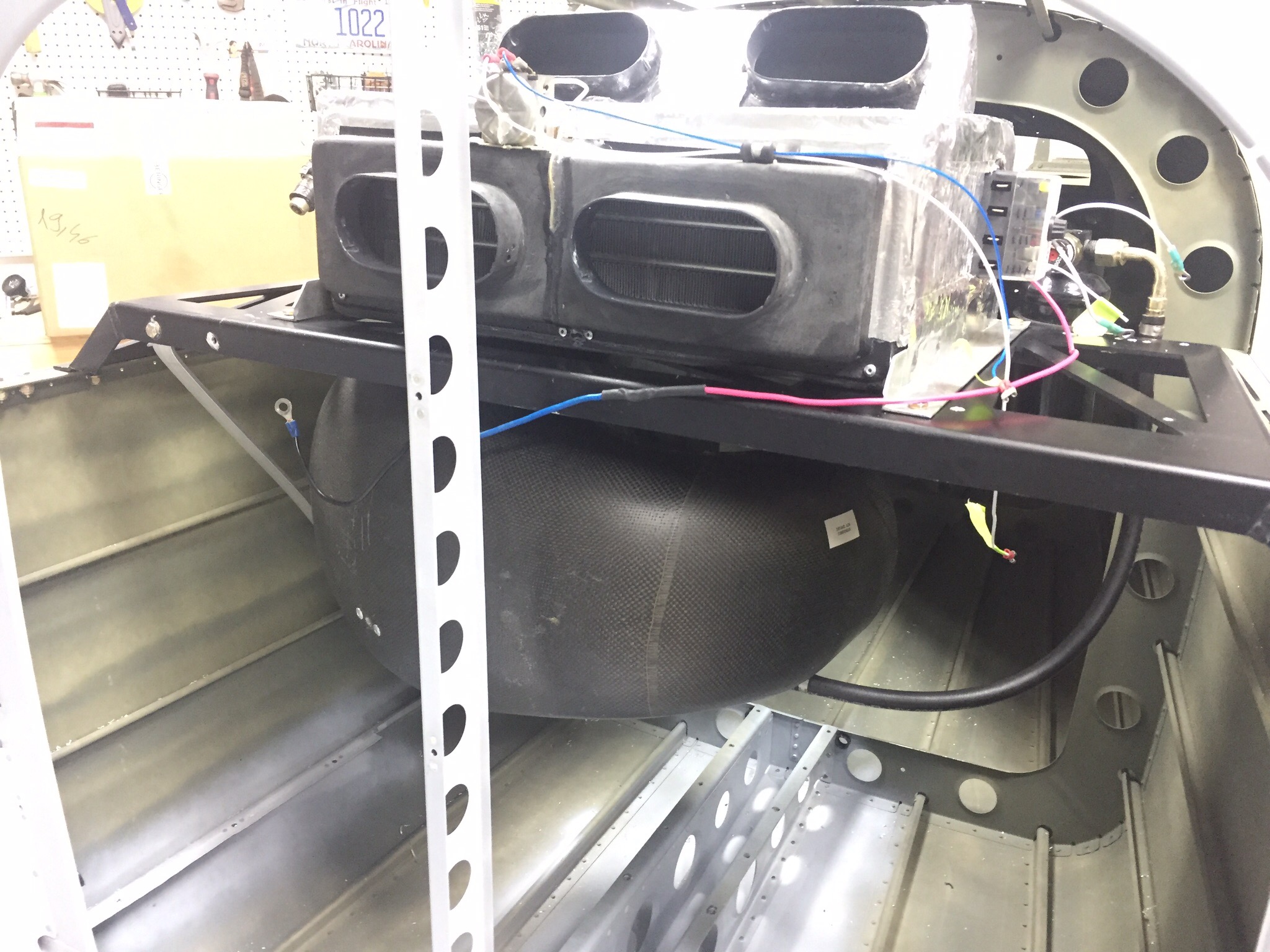
The next task was to mount the intake and exhaust vents for the condenser. While at Oshkosh, I spoke with John at Flightline (owned by Kelly Aerospace now) about an alternate side mounted intake. There have been some builders concerned about CO infiltrating the cabin with the original belly mounted vents which are in the exhaust stream. I agreed to design a new side mount intake similar to Cirrus retrofit kits. While I am in the process of laying up said vent, I ultimately decided that I was comfortable with the stock setup and ended up going that route.

I created a paper template of the vents after cleaning the old silicone caulking from them and cleaning up the rivet holes (this was a used kit pulled from a flying RV-10). I used the template to mark the holes and cut lines on the bottom of the tail cone. I measured fifteen times and cut once with success!
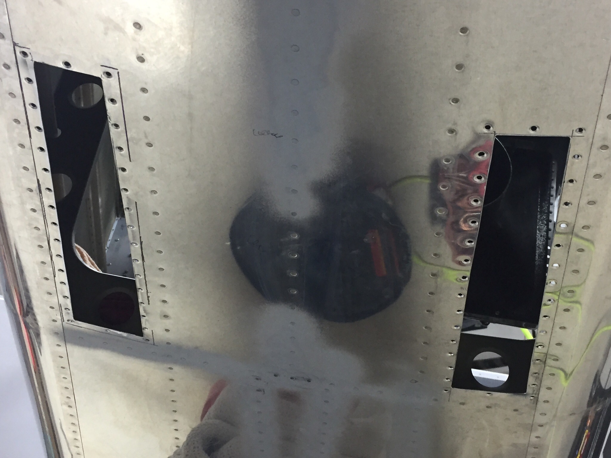
I used black RTV to create a good seal around the vents which will prevent air from leaking into the cabin area. Once riveted in, I was really happy with the results and finished up by connecting the 6″ duct work to the plenum and securing the clamps. I also added a new drain line from the evaporator which runs down into the exhaust vent and secured it using more RTV.
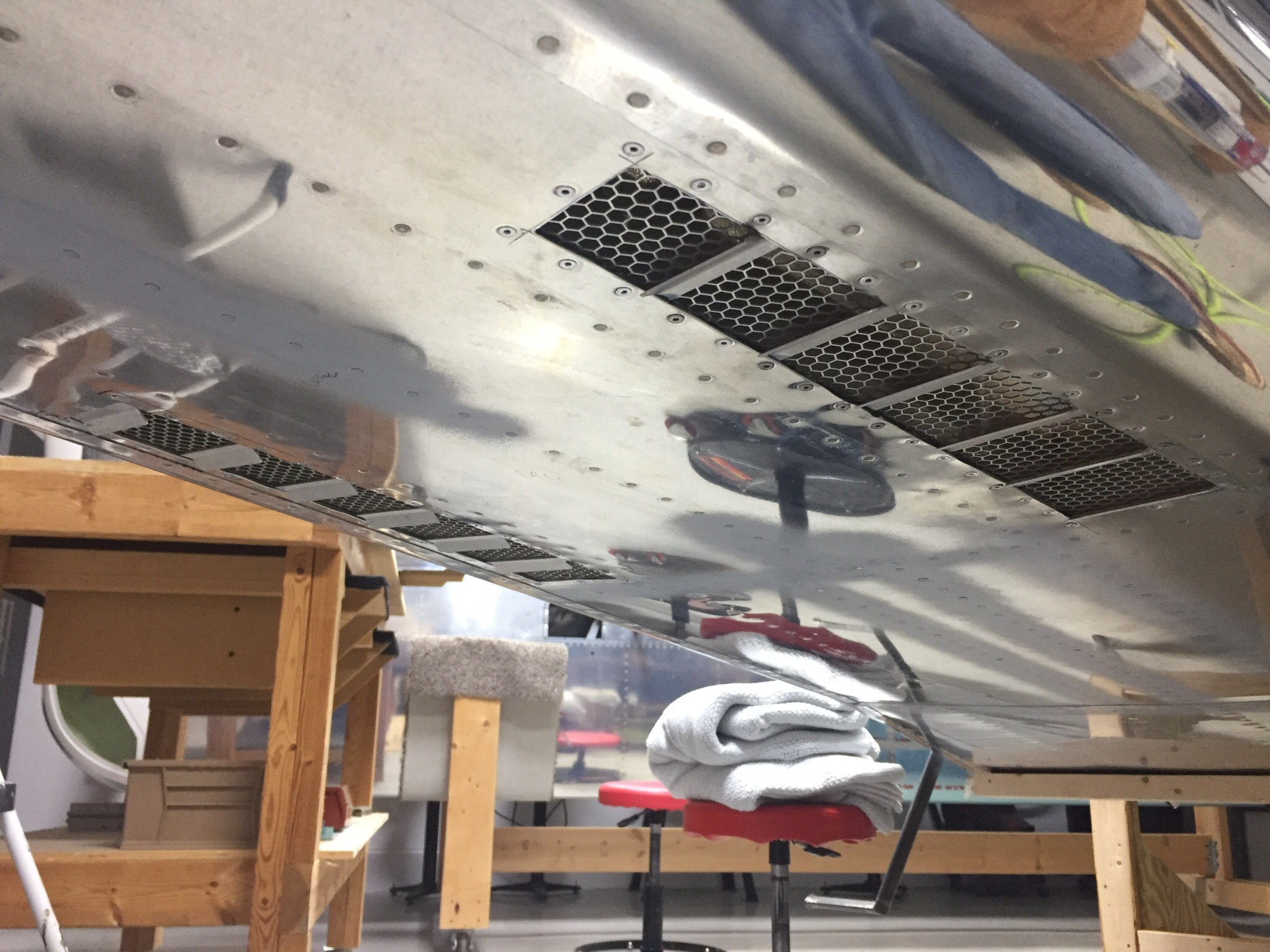
I’m really excited to have this done and happy with how it turned out. I chose this kit vs the Airflow system because of it’s low profile install and electronic controller which is really slick. Users have reported good performance and this will make our adventures even more pleasant by keeping the cabin comfortable in the southern summers.

We have some catching up to do

Time has gotten away from this blog, so I have quite a bit of catching up to do. I also must admit that there were more than a few months that snuck by with no progress made on the project due to work, life, and other priorities. I’m happy to report that I’m back on the project nightly and am really making some exciting progress.

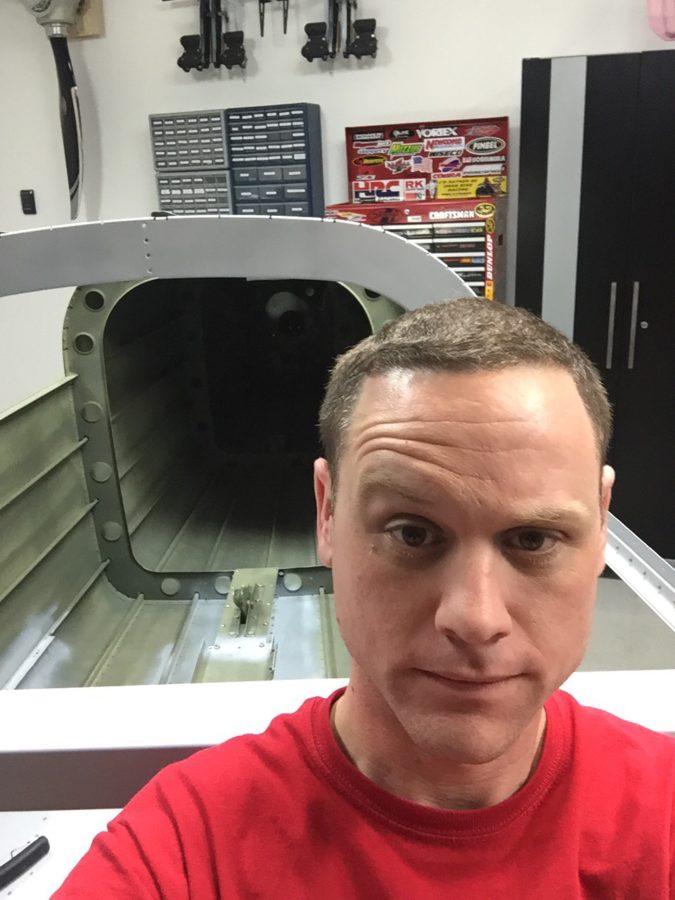
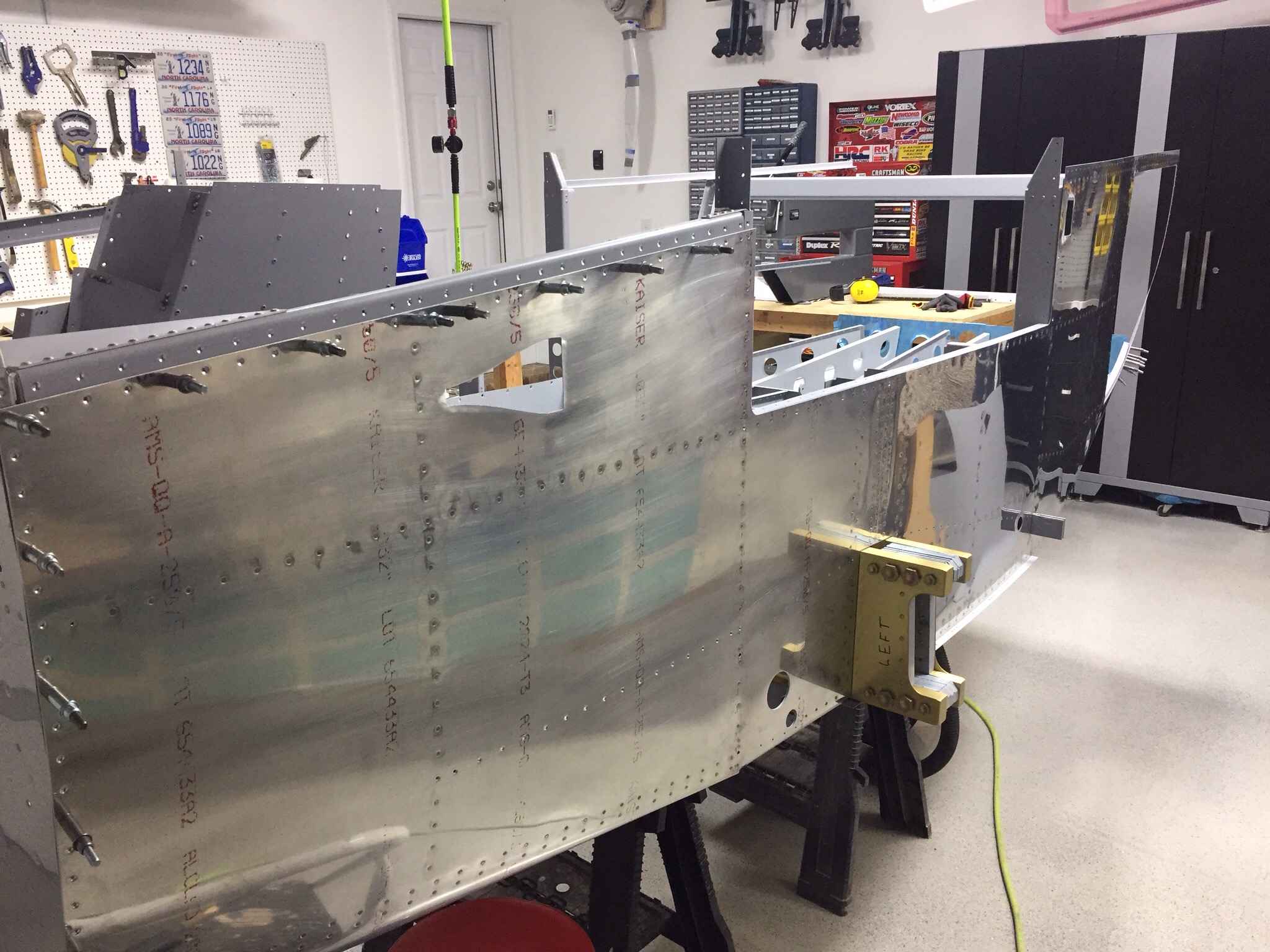
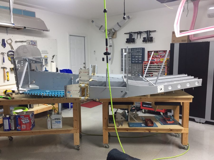
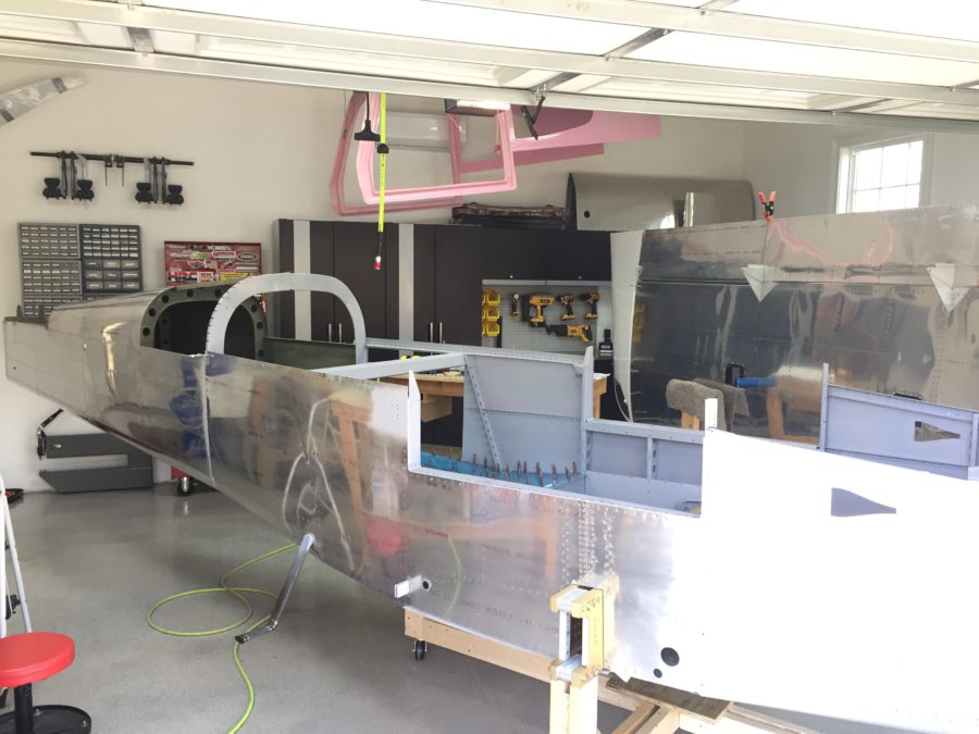
I left off with the tail cone repair and prepping to join the two sub structures. It was very anti-climactic to be honest! One rib worth of rivets required a bit of help from a friend to hit some rivets and boom, it was on for good. It really is starting to look like an airplane, or at least a canoe at this point. I’m very happy about the cradle on wheels, as the shop is getting a bit cramped on space, although I’m confident it will still be a nice workspace for the remainder of the project.

I pressed on with the steps, as you can see above and used the TCW step bushings to prevent the mounting bolts from crushing the tube and creating issues down the road. I attached the antenna doubters and am happy with the results. They are actually under the rear seat pans, not the baggage floor as previously mentioned.

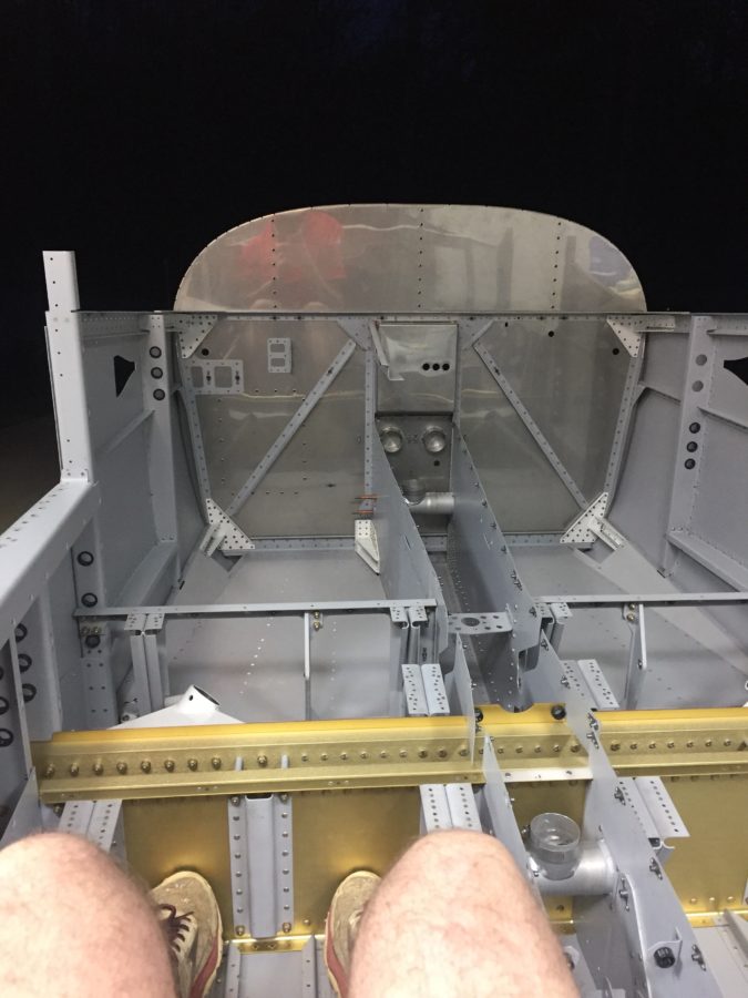
Next up is the baggage floor, rear seat pans, and rear bulkhead. Lots of drilling, deburring, and priming but the work went fairly quickly. One thing that has always impressed me is the size of the cabin in the RV-10 and now that mine is coming together, I had to see how roomy it actually is. First time sitting in the plane! And no, I didn’t make any airplane noises quite yet since I was sitting in the back seat. Plenty of leg room.

Lot’s more to catch up on in the next post.

Taking a new stand

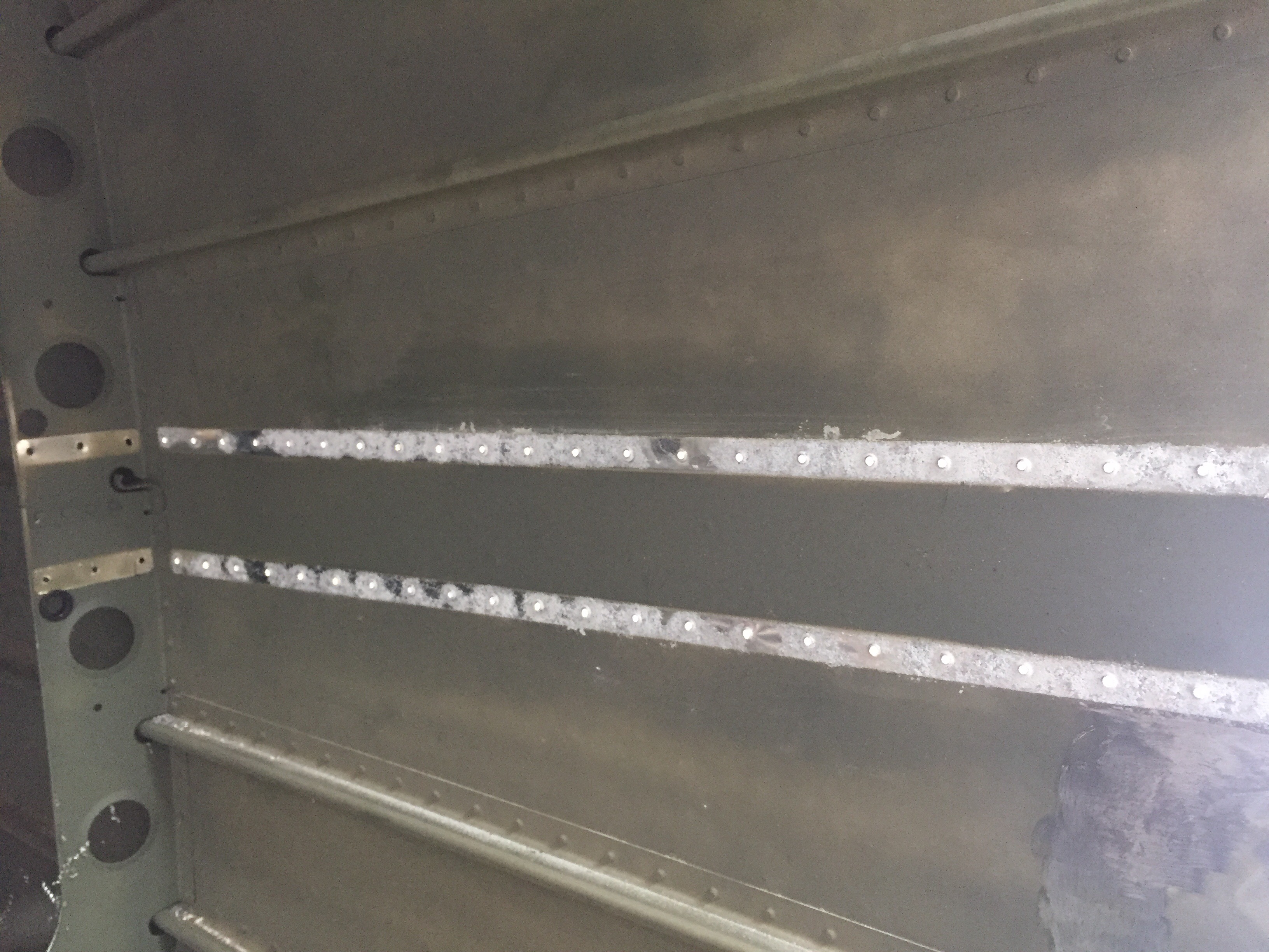
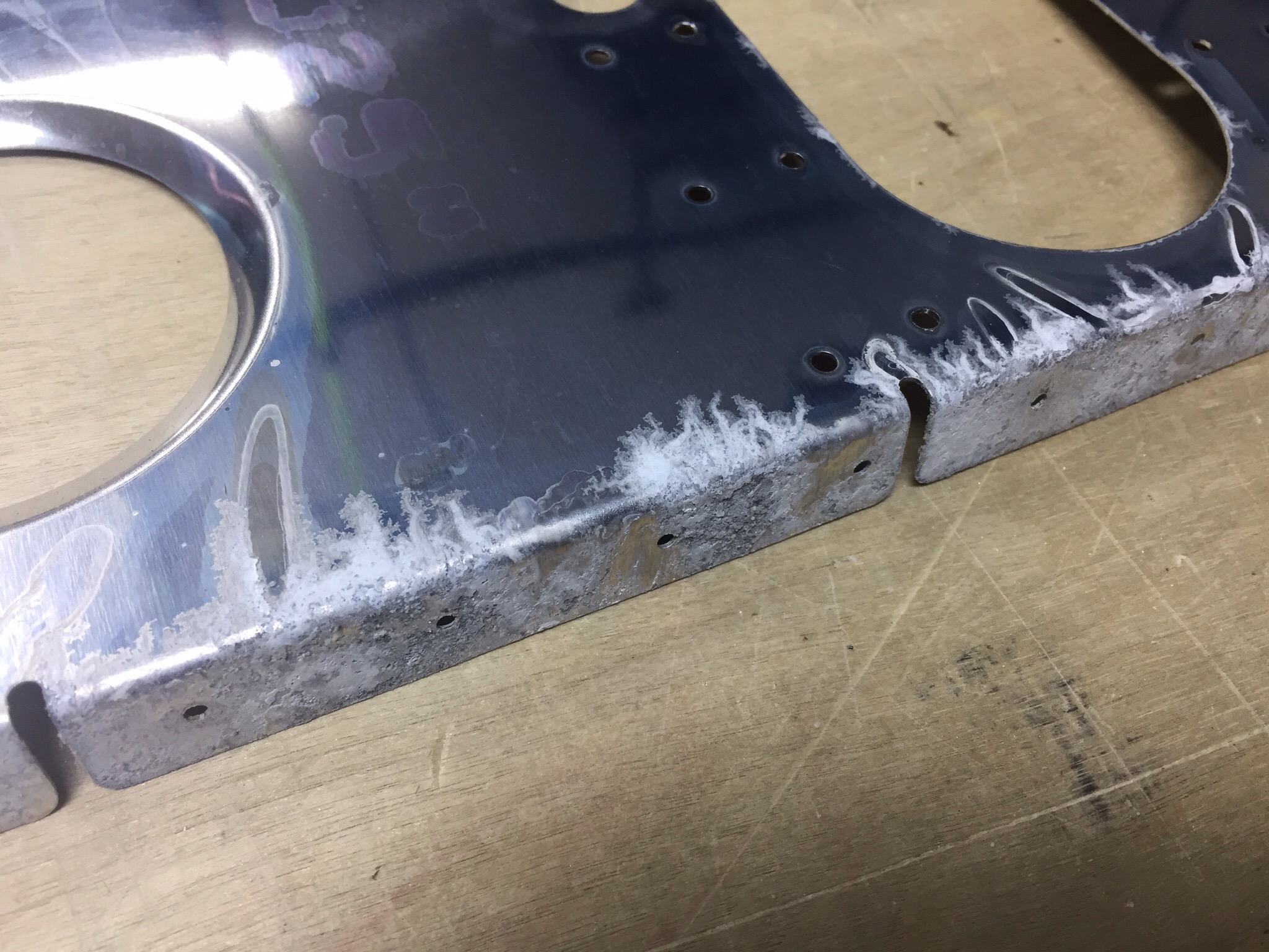
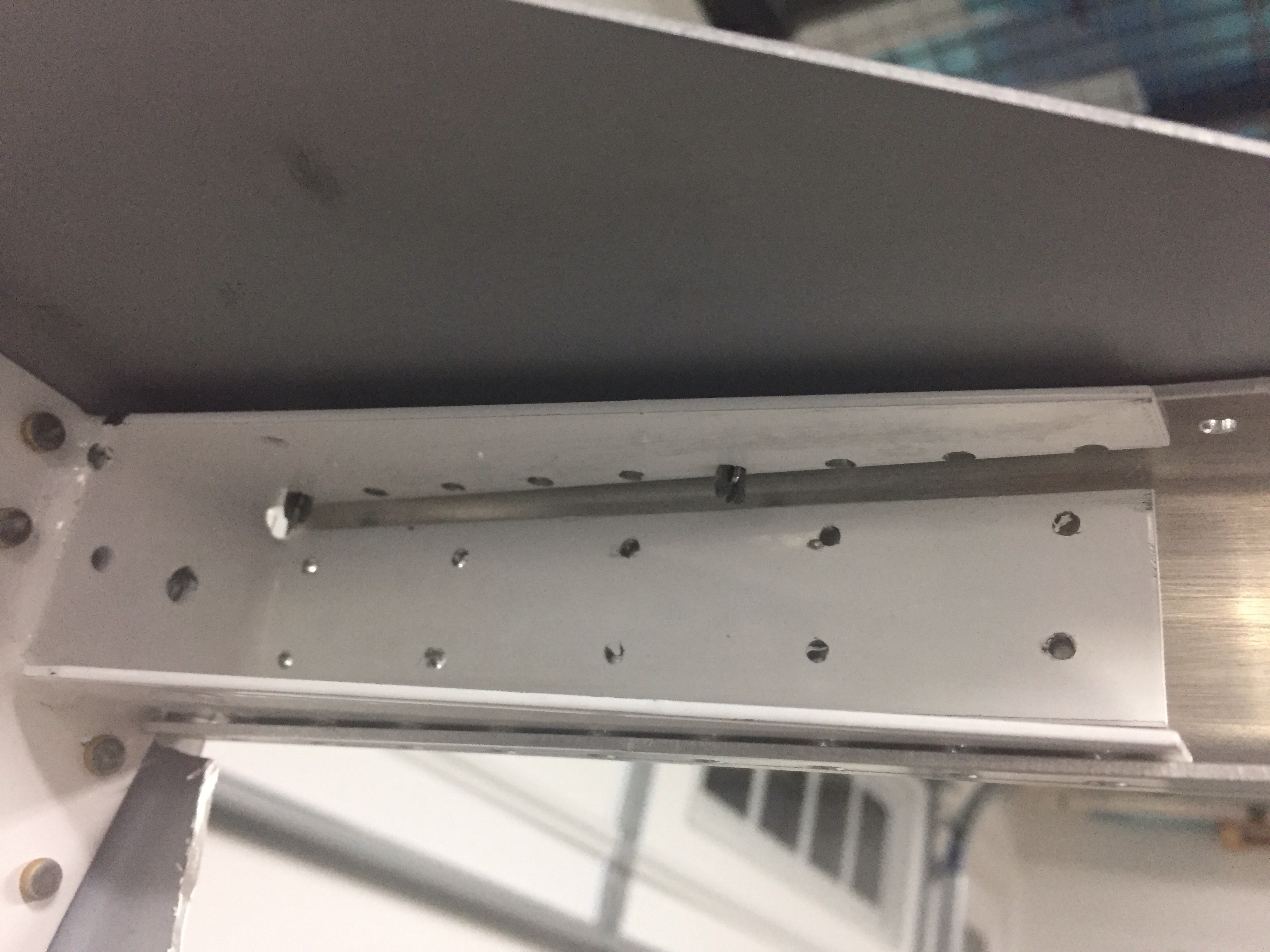
After drilling out all the rivets and removing the two ribs with feared corrosion, my suspicions were confirmed with a somewhat scary sight.


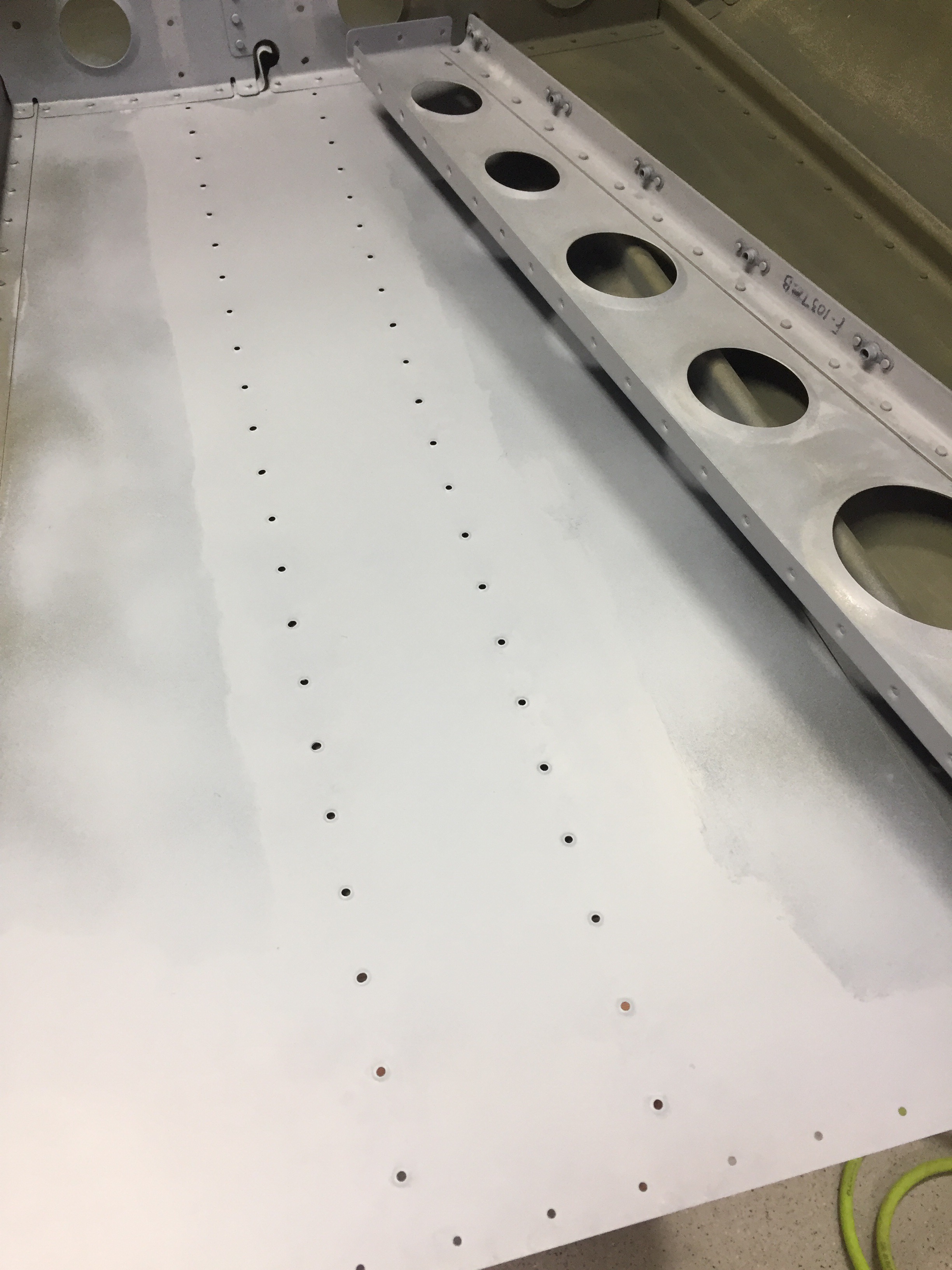
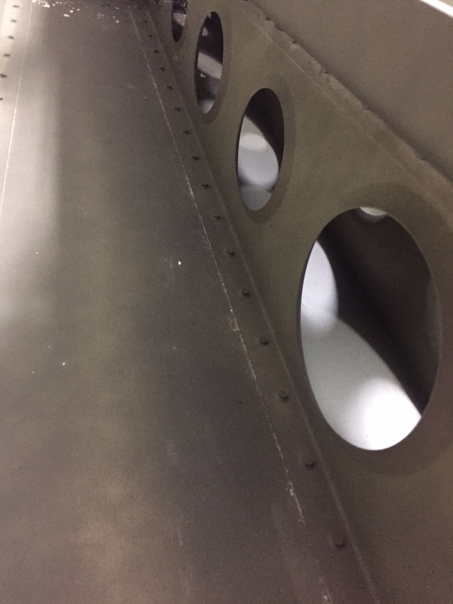
As you can see, there was quite a bit of corrosion between the two surfaces.  I’m very happy I took the time to correct this and avoid potential problems down the road.  I spent more time inspecting other areas of the tail cone and could find no other signs of corrosion, so I’m confident this is the extent of the damage.  It took a few 3M pads to get all of this cleaned up, but after about an hour it was down to shiny smooth metal again.  I was concerned about how much I had to grind away on the bulkhead, but a call to Vans alleviated my fears as they said I should be good to go.  I removed the original primer (which was not applied very well, I admit) and did a thourough wipe down with MEK before properly priming with my SEM.


I did notice a small stress crack in the bulkhead lightning hole flange that I stop drilled upon Vans’ advice.  I was able to move forward after this brief fix delay and was back on track.  However, the next step was to mate the tail cone to the fuselage assembly.  That requires getting rid of the sawhorses and coming up with a long term stand for the fuselage structure.

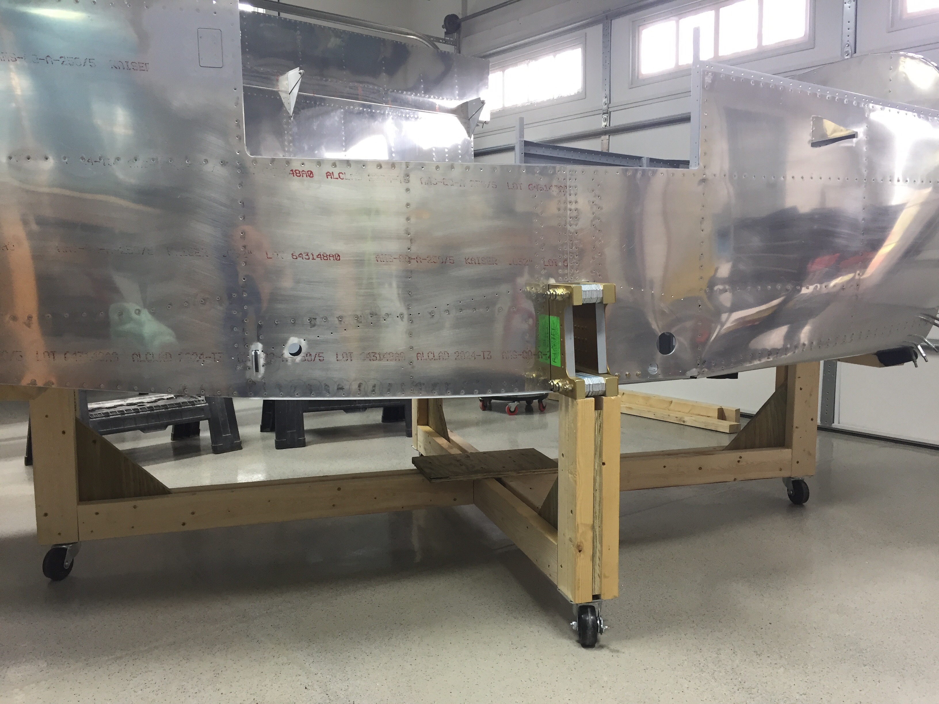
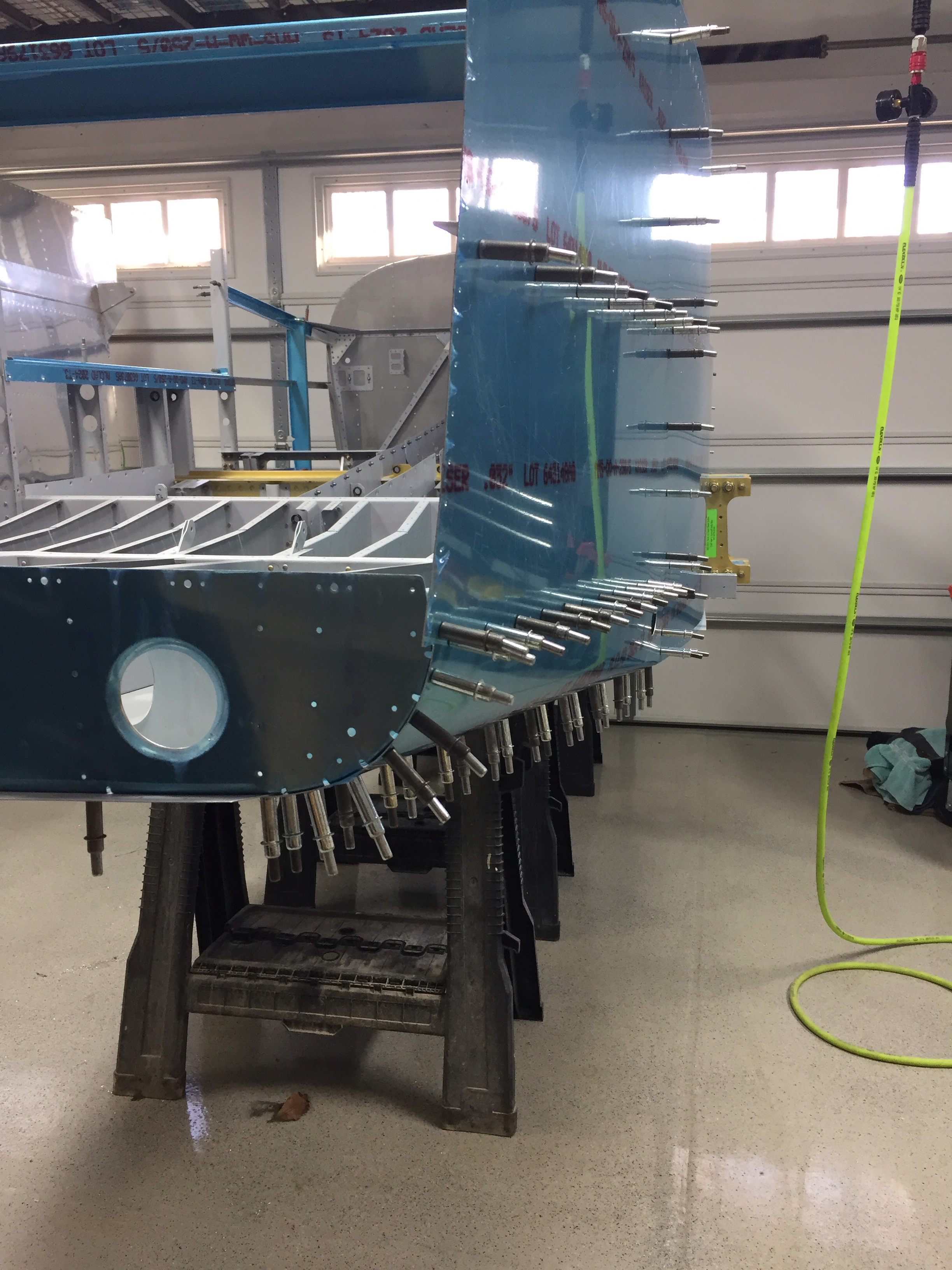
I checked out a few other build logs and decided to copy Justin Twilbeck and went with a four caster design with pillars for each side of the spar pass through and one each for the firewall and bulkhead near the steps.  Using 2x4s and some OSB, I estimated the deminsions putting the structure at a nice working height, keeping in mind the cabin top and the height of my garage door.  I won’t be able to mount the gear free hanging on this stand, but it will allow easy access and a comfortable working height for the next year or so.  I put a bit of felt on the two bulkhead cross pieces and am pretty pleased with how securely it holds the fuselage.  It also rolls quite easily which is good because the shop is filling up quickly!


Next up is actually mating the tail cone to this subassembly.

Spring cleaning: cobwebs and corrosion

It’s time to attach the tail cone to the fuselage which means a museum piece can be ceremoniously lowered from the ceiling and brought back into production.  The last work was done over two years ago on the tail cone and it’s been in storage, basements, and garages since then.  Unfortunately, moisture left its mark with some heavy filiform corrosion on the bulkhead and bottom skin.


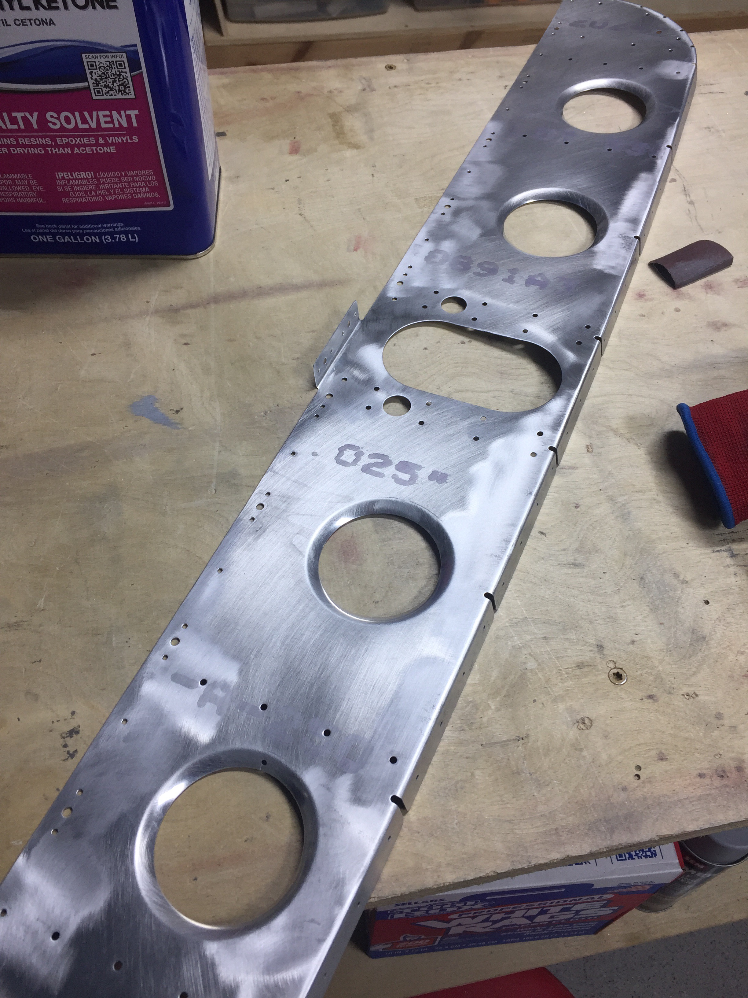
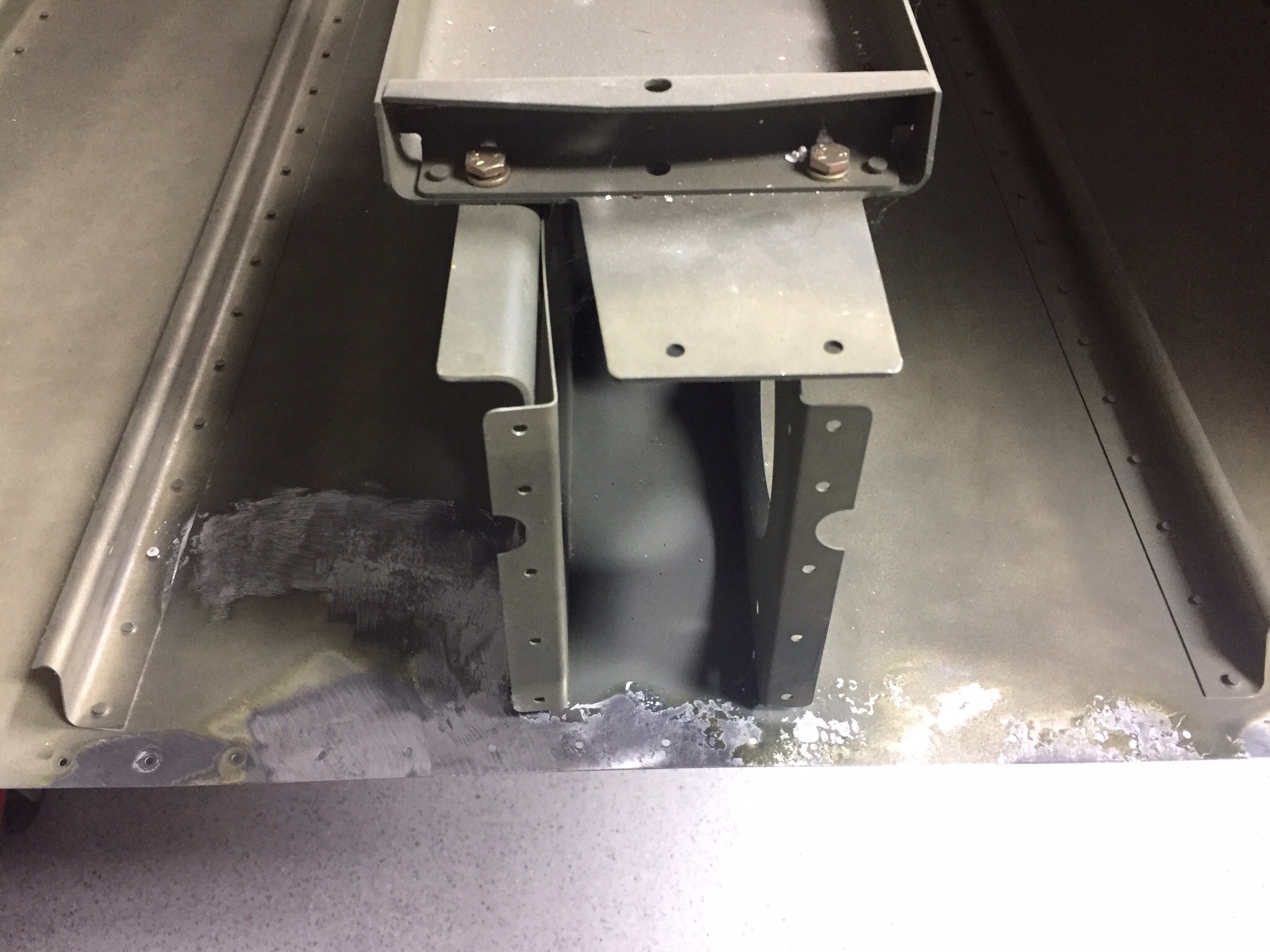
The tail kit components had this elsewhere when I purchased it, but never this bad.  On the bulkhead, I dug in with the angle grinder and 3M pads and made quick work of the nasty stuff.  Fortunately, it wasn’t too deep in the metal and it all came off easily.  The bottom skin is a bit trickier with the DuPont primer on it.  I didn’t do a great job priming this and did it after assembly so there were areas the corrosion was actually underneath the primer.  I’m not quite done getting that part cleaned up, as evident in the picture.

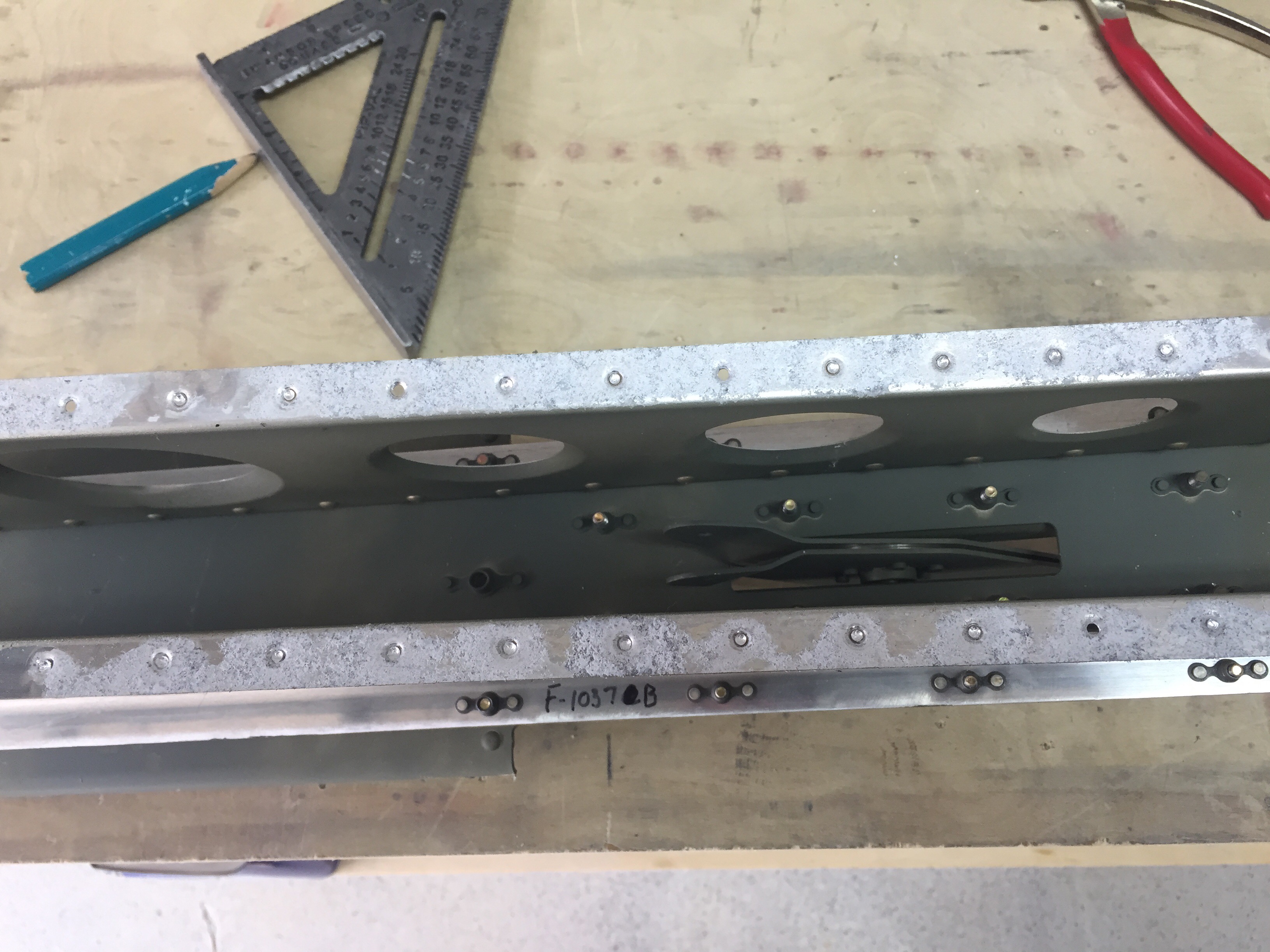
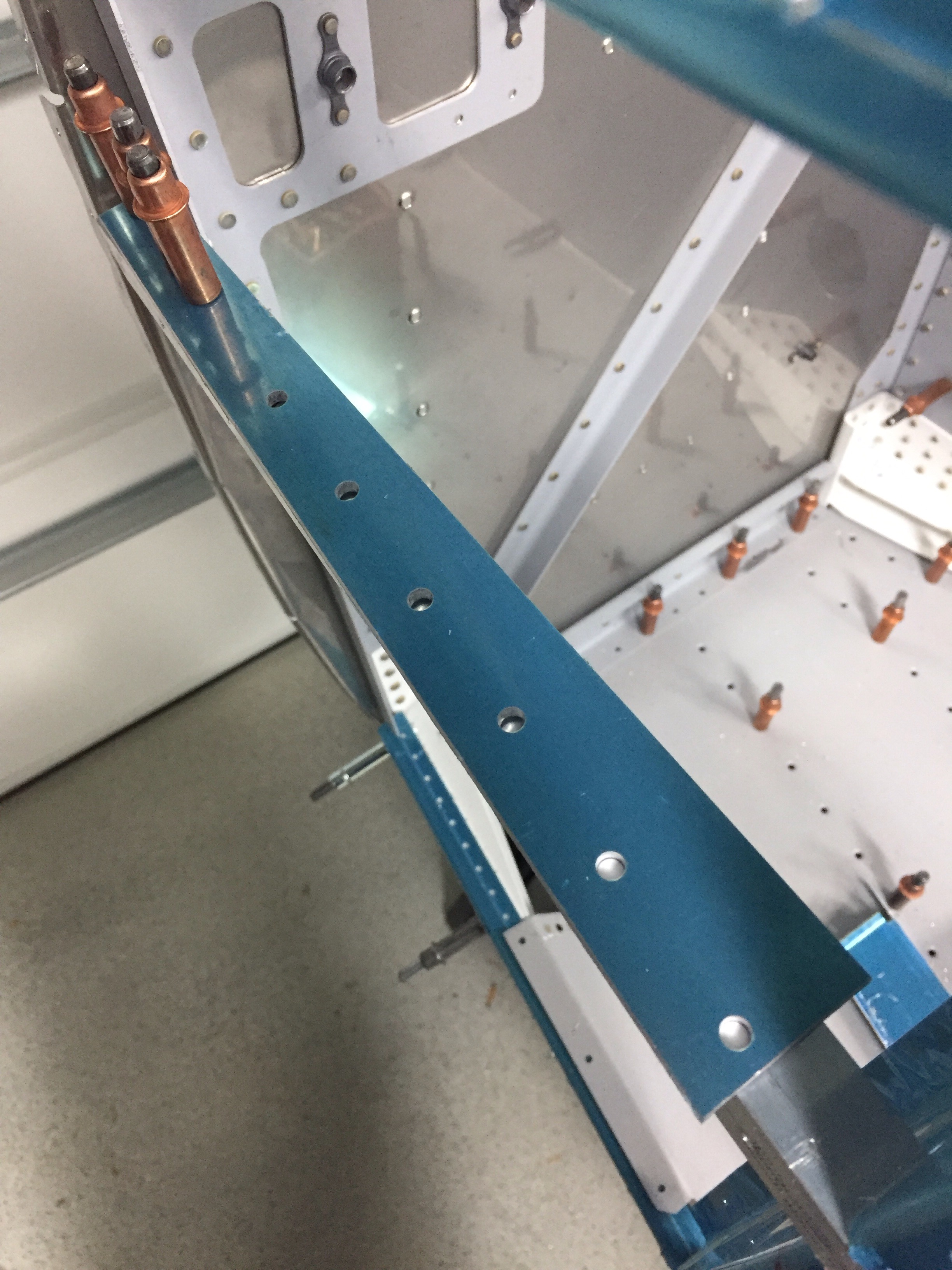
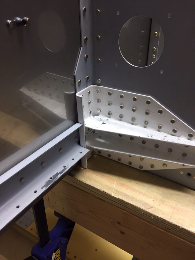
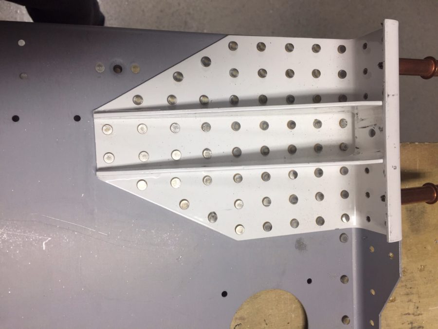
The biggest concern, out of it all, is the thin line of white corrosion along the ribs holding the battery tray (ignore the white flakes in the background, I haven’t finished vacuuming).  The surfaces between those two parts aren’t primed and I’m suspicious that there is corrosion between the two.  


I spent a good amount of time with a flash light and inspection mirror going over the rest of the tail cone.  It’s the only area like this and I don’t want to risk long term issues.  I concluded that the right thing to do is to drill out the rivets and clean these areas up properly.  It’ll be easy to do now and I’ll combine this with the custom equipment tray that I’ll be putting in to replace the battery tray.  Once this is complete, we’ll move on to attach the tail cone.

Pop goes the rivets

Section 29 has proven to be a lot of work but the results are more than worth it.  With the help of the Mrs. again, the four side skins are riveted on now and I’m pretty happy with the results of the bending.  I was able to get the new engine mount bracket drilled and riveted to the firewall with better results this time.  After the side skins were on, I was able to get the front floor panels on.  These are pop riveted onto the structure and I’m glad I’m not building the entire airplane with pop rivets.  They are almost more work than bucking.


The landing gear mounts had to be finessed into place and led to a bit of a panic attack on my part.  While bolting them in, I realized the spacers for the two long bolts weren’t fitting quite right.  After a lot of measuring, I determined the spars were a bit too far apart according to the plans.  If the spars are off, this could be a huge concern.  After a post on VAF and a call to Van’s, I figured out that I didn’t remove the vinyl from the spacers and also didn’t insert the right spacers into the spar during construction.  I lucked out though and the spars are only .002″ off after its all said and done. That was close enough for me and Van’s so I pressed on with as it was.  Adding a thin washer fixed the spacers and the other two for the right side was cut a 1/32″ longer.


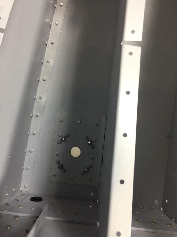
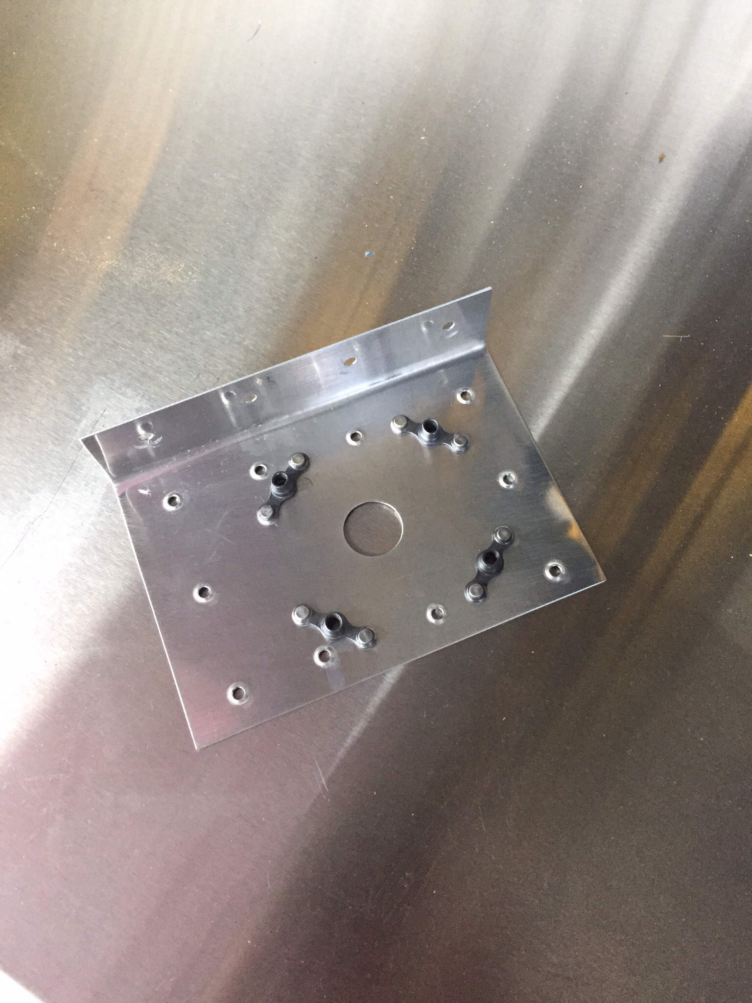
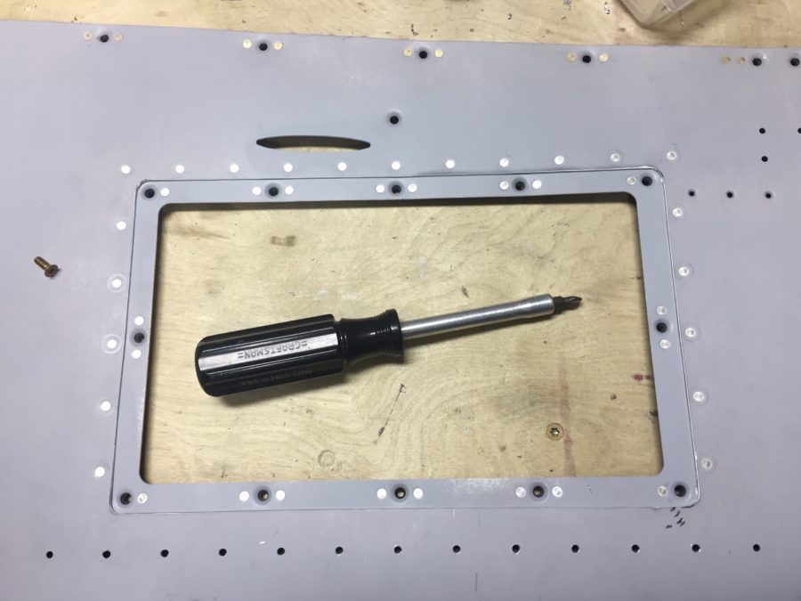
I also made up a couple of doublers for the comm antennas mounting on the belly.  I’ll be using Comant CI-122 VHF antennas and went ahead and installed nut plates since there won’t be acces from inside once the baggage compartment floor is in.  The doublers will tie into one of the baggage compartment floor ribs.  I will make two more doublers for the Delta Pop ADSB and transponder antennas which will go in the tunnel.


A lot of riveting evenings later, the skins are on and I’m ready to move on to the steps and pretty soon the tail cone.  

Some woodworking required

Once everything was match drilled and after the mistakes were handled, prepping began on the many pieces assembled over the past week.  Edge deburring is my least favorite and takes a lot of time and effort, especially on these formed pieces.  But it is important and accomplished after a few nights of work.  Dimpling and priming the skins went quickly and riveting won’t be too far behind.

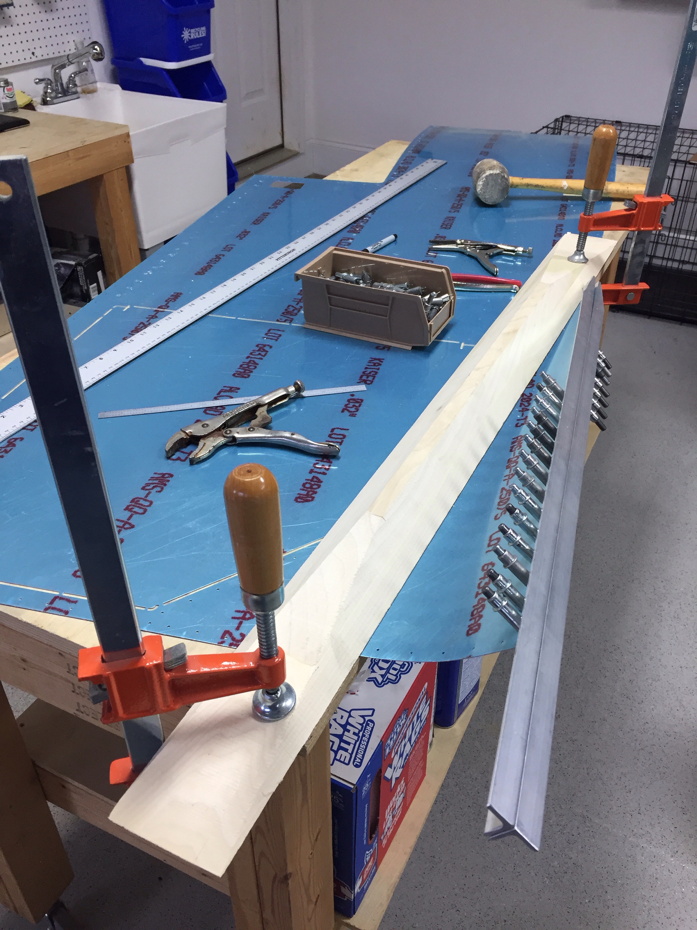
One interesting part of the build is the special tools that are required.  The latest one is a bending aid made of wood used as a clamping block for the side skins.  Each of four skins needs a rounded bend placed in them to transition from the tail cone / firewall to the more boxy part of the fuselage.  While I could have made it on the table saw at home, I elected to enlist a fellow aviator with a wood working shop rivaling the New Yankee workshop by Norm.

Just like most projects, preparation is 75% of the work but we set all the tools up and made the block of wood into the trapezoid shape required.  When put in use, it took a lot of grunting to get the skins bent.  A rolling and bending motion is used to form them and I was pretty lucky with getting a good result with the first attempt at each one.


A couple of oops

Mistakes are inevitable and I uncovered a couple of them back to back.  With the longerons fitted and finessed, the other structure went together pretty easily.  More bending was required as four forward channels required a good twist using the vise and a strong arm.  There are also quite a few other pieces that fit along the side forward of the spar.


A lot of match drilling comes next, as the longerons need holes drilled for the sill and skins.  A drilling template is used to drill holes for the rudder pedals and is where the first mistake was uncovered.  The longerons are not an exact science, so the guide didn’t line up perfectly.  A quick email to Van’s gave me guidance to line the template up with the edge of the longeron and all was well.  


Unfortunately the next mistake was not as easy to correct.  The engine mount brackets tie into the twisted channels and get drilled using the holes on the flange already riveted to the firewall.  I realized that three of the holes weren’t in the flange completely.  This is a major component providing support for not only the engine but the landing gear and forward fuselage, so certainly a cause for concern.


Van’s stated that it’s pretty common to have thin edge distance on these but all holes did need to be in the flange.  What I don’t understand and never got any response from is why the holes didn’t line up.  The mount is welded from the factory and cannot be bent or adjusted by the builder in the direction that is needed to correct the issue.  Replacement was my only option so an order to  Van’s was placed.  I am proud of my skills at removing the rivets, as I did not want to mess up the firewall.  All went well, though, and I’m just waiting for the replacement part to come in.

Longerons take a long time

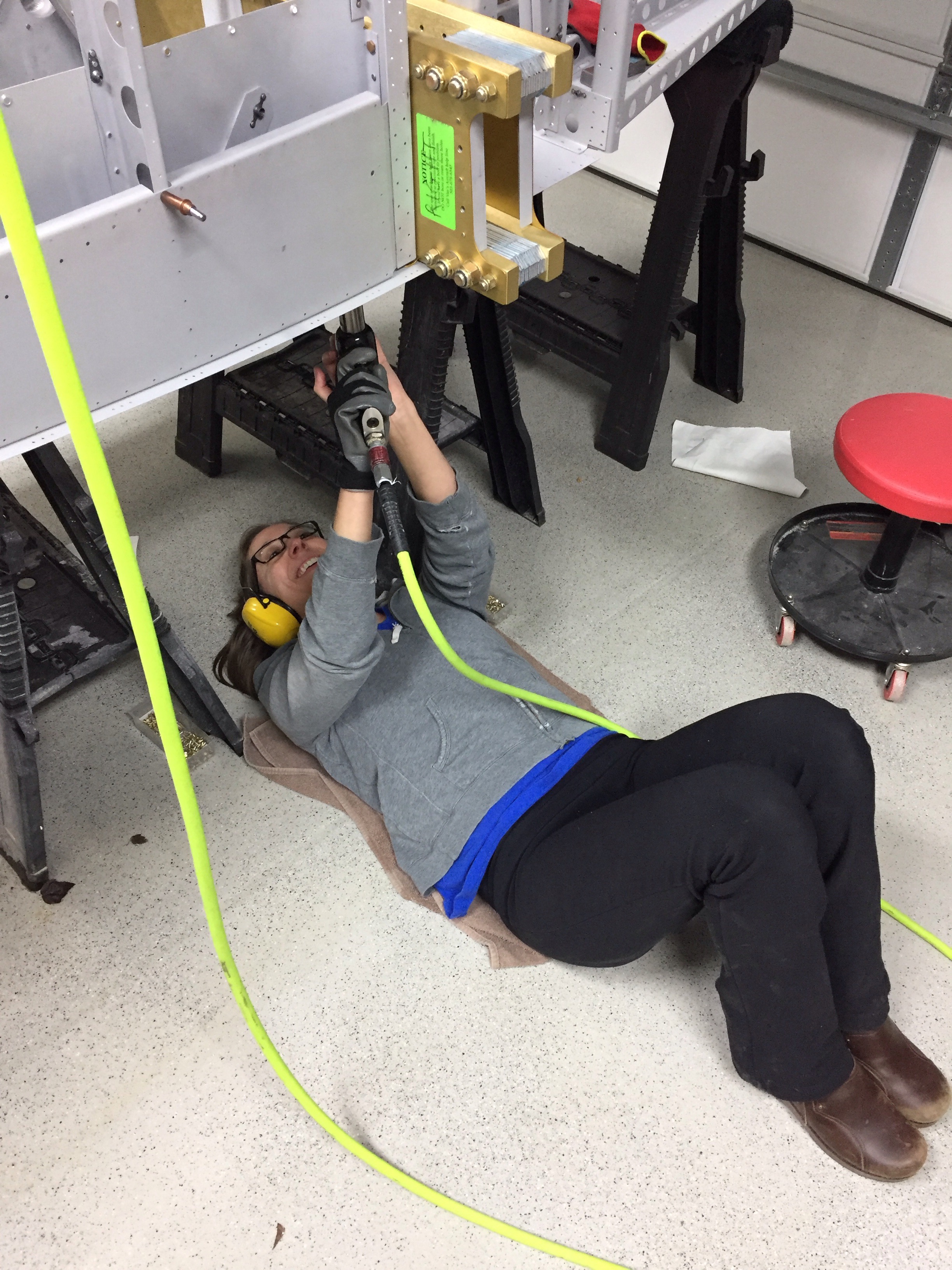
It took quite a while to prep all the pieces, but after a lot of boring tedious work, it’s ready to put the two pieces of bread together and bang some rivets.  The wife came out in her steel toed shoes for safety and was kind enough to lay on the cold floor while I manned the bucking bar.  The work went quickly and we only had to drill out one rivet!


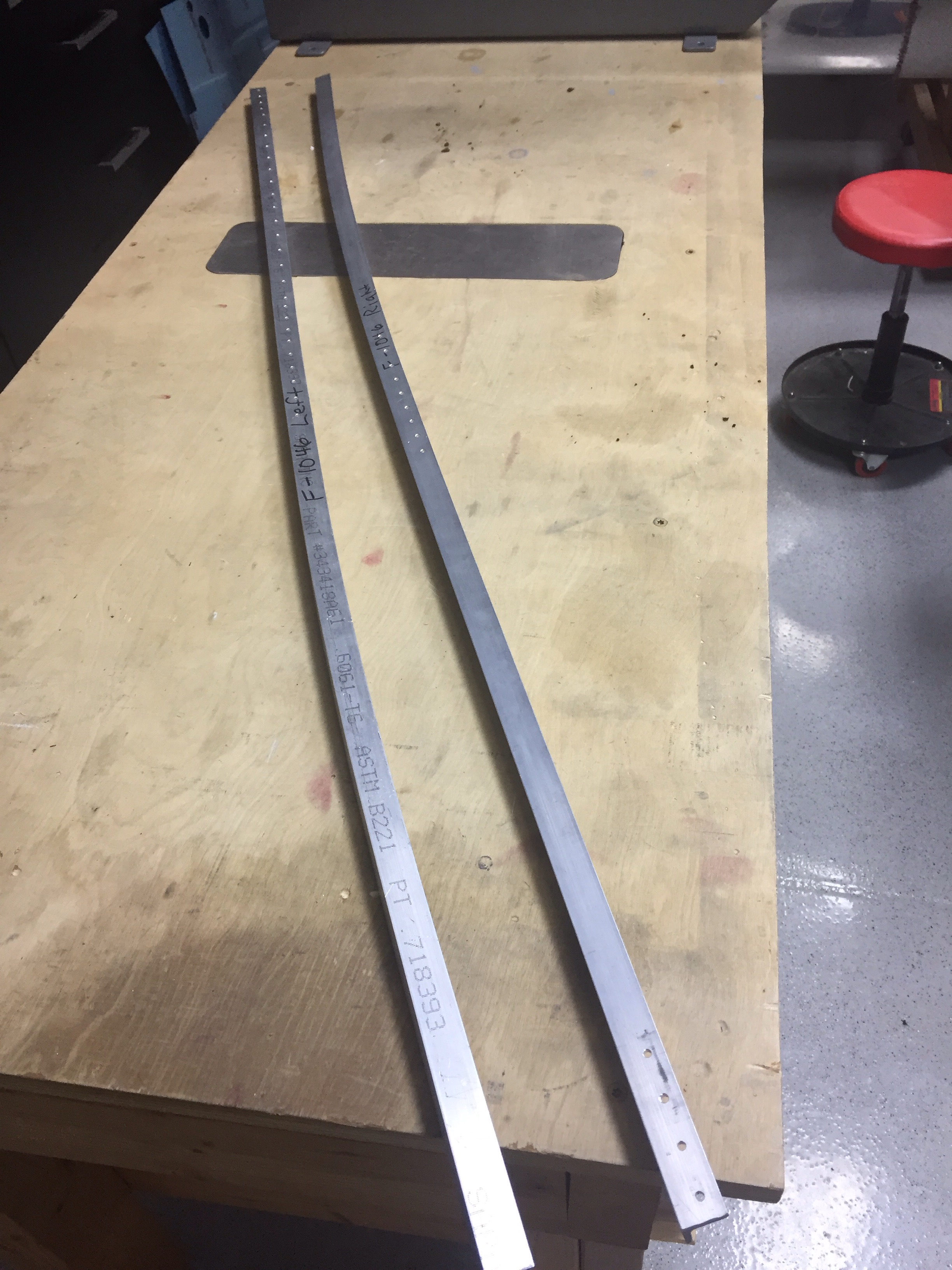
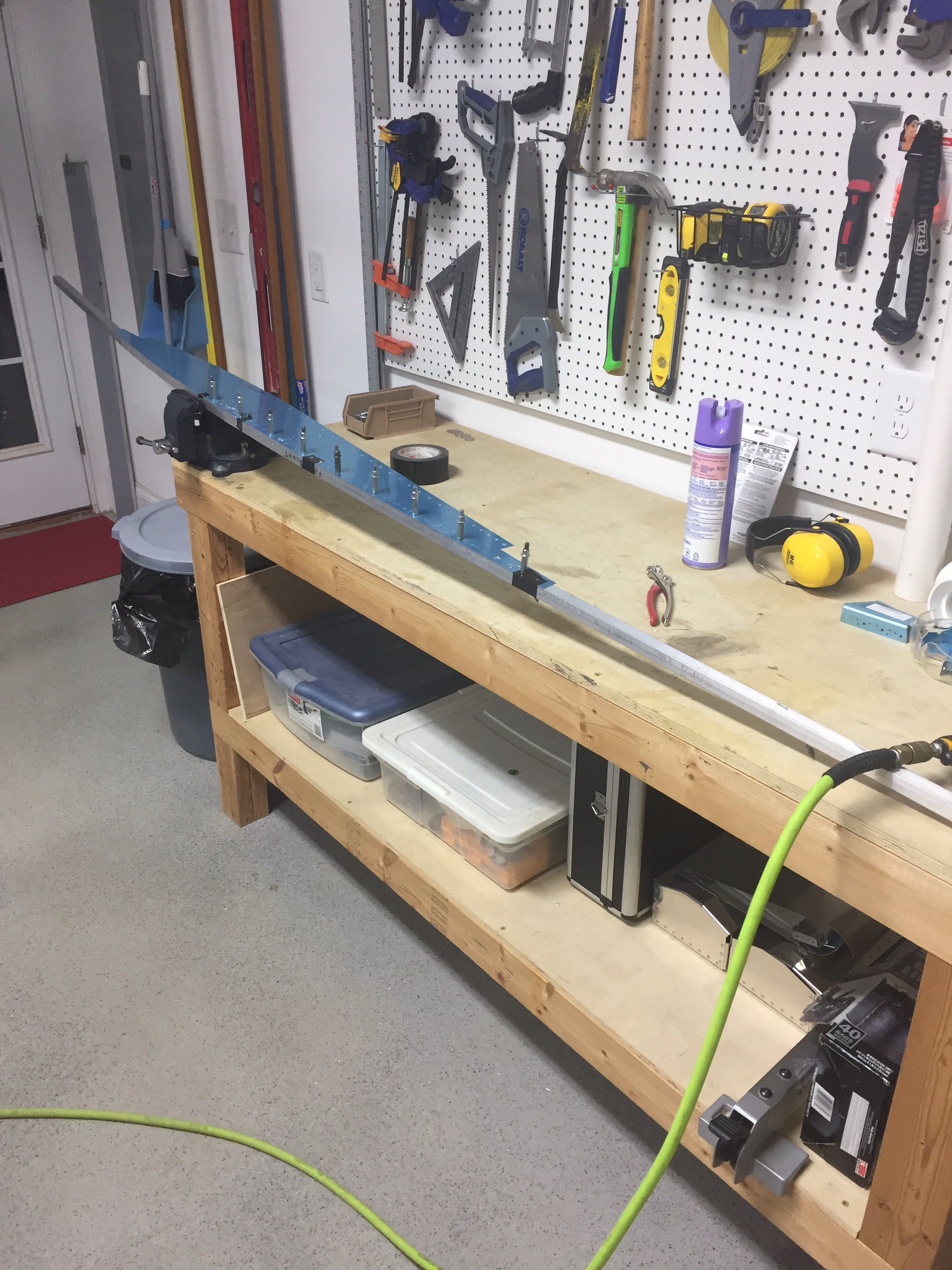
With the bottom of the fuse complete, the sidewalls are next and involve a bit more metal working than anything thus far in the project.  The main support pieces on the sides are made up of longerons which are formed from a 3/4″ angle iron that is 1/8″ thick.  The plans call for putting it a vise and smacking with a rubber mallet, using a bending jig to ensure the proper curve is met.  Another builder used a neat trick of putting a few nickels in the vice and using it as a manual bending machine.  I decided to give it a shot and was pretty happy with the result.  However, it took forever to get these four pieces done.  As soon as you got the lateral curve set, the vertical plane would be wrong.  So it was a laborious process of bending and rebending.


I did stall at this point for some time due to home improvement projects, back to back drill weekends, and a few other things going on.  But taking a weekend getaway in the DA-40 and running into a fellow 10 builder randomly rejuvenated my building motivation and I finally finished destroying nickels in my vise.  Taking a long break isn’t always the best for the project, as I realized that the first longeron I tackled after getting back to the build was done wrong.  Fortunately I was able to correct the wrong curve and didn’t mess it up beyond repair.  I confused my template labeling and used the wrong side of the template so had an incorrect curve.  Next up is to put them in place and start working on more of the structural component for the side skins.

It’s getting cluttered in here

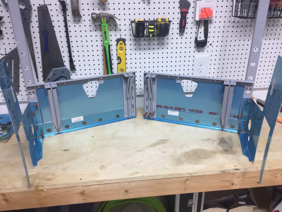
The forward fuselage has a lot of structure that will support a very important piece of my body:  my butt!  I am finding that it’s critical to follow the plans step by step and not jump ahead to what you logically know is coming next.  Plans are there for a reason, and there’s always a got ya  if you don’t follow the steps.  Fortunately, I didn’t have any issues with this section and pieces easily came together.

I asked a favor from the sheet metal shop at work and a metal tech went above and beyond letting me use the industrial band saw and cleaned up my cut with the mill on the control stick mount.  Really a work of art and now it looks like a professional cut piece.  Even though it will never be seen, it makes me feel good knowing it was done right!  I finished sealing the firewall with RTV using a pastry bag type applicator and a sandwich bag.   Worked like a charm.  While fitting the tunnel walls to the bottom skin, I discovered that the three nut plates were installed on the wrong side.   So I fixed those as well.

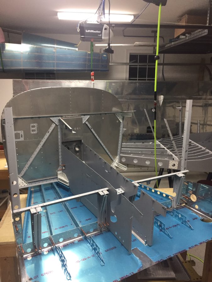
By the end of it, the forward fuselage and mid fuse sections were ready to mate together.   I really struggled getting the bolts into the spars as they are an extremely tight fit.   This was a case of not using a big enough hammer.  I started with a rubber mallet and quickly switched to my traditional hammer.  It got the job done and before I knew it, I was standing back admiring a very big assembly!Alas, as everything in building an airplane, this was only a tease since it all had to come apart for the typical deburr and prep for final assembly.  It doesn’t look like a lot, but it took most of an evening just to prep all the parts and prime them.  It’s certainly my least favorite part of the project, but a necessary evil.  Next up will be assembly and clearing off a workbench!

Firewall Fives

It seems like sometimes it takes me five times to do something right.  The firewall is no exception.  But I am getting ahead of myself.  The next section is the forward fuselage from the firewall back to the spar.  The firewall is a beautiful piece of stainless steel that protects the cabin from the engine compartment and acts as a fire barrier.  There is a lot of structural components on it as well.  After the usual process, I set to riveting.  Bucking the flush rivets went well until I realized that one of the tunnel walls did not seat correctly and I had to drill out 20 or so rivets to correct it.

After the correction, I set about sealing up the gaps in the firewall recess and bolting the aftermarket stainless steel heat valves from Aircraft Spruce.  I also installed the Airward tunnel access plate before riveting the tunnel wall to the firewall.  This will allow easier access to the tunnel and fuel system components once the interior is finished.


One item I might have messed up on is the landing gear tension plate.  The plans stated the shop heads of the rivets needed to be on the outside of the tunnel, but I neglected to read and head on the first wall.  Hopefully that doesn’t bite me down the road, but I can’t find any reason other than ease of bucking.

Firewall section is complete now and Laura helped me gather all the parts for the next step tonight so I only had to make 50 trips up and down the ladder.   So it seems that sometimes I do things right the first time, and other times it takes a few more tries!