Stabilizing success

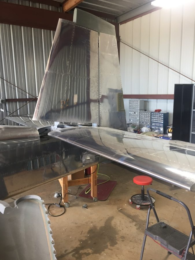
I skipped a major step during the tailcone build sequence by never installing the horizontal and vertical stabilizers onto the tail cone. I didn’t see a point of doing that in the garage just to take it all apart again for storage for years. Now that I’m in the hangar and have the room, no excuses are left. I didn’t build either stabilizer, as the original tail kit owner built them. After looking over them and cleaning them up, I “touched up” a few of the rivets I felt were under squeezed. They aren’t primed on the inside either but even after 10 years of sitting around, they are looking good and corrosion free.
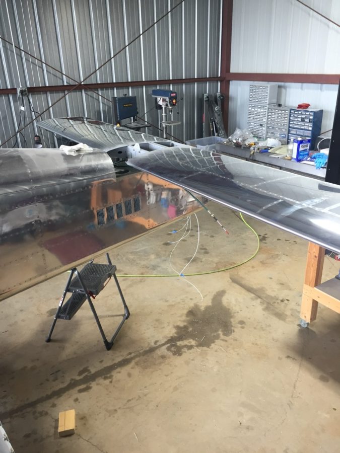
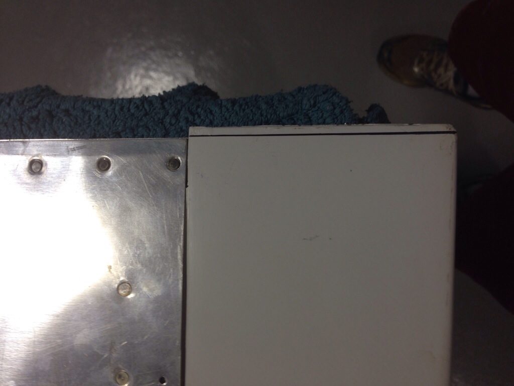
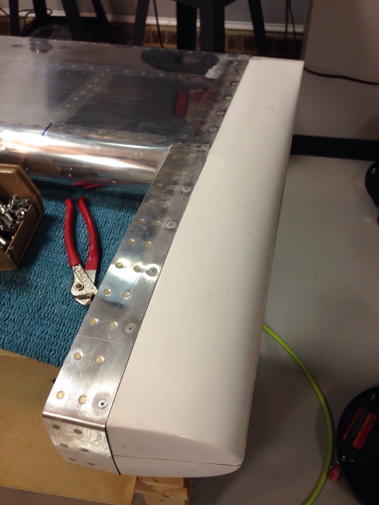
The process went as planned and I spent the better part of one full day getting it all drilled and bolted on. I had purchased the CNC brackets from somewhere to mount the horizontal stab so I didn’t have to make them. I have no clue where I got them from, however, as I bought them on a whim years ago. Either way, they’re nice and you should buy them.

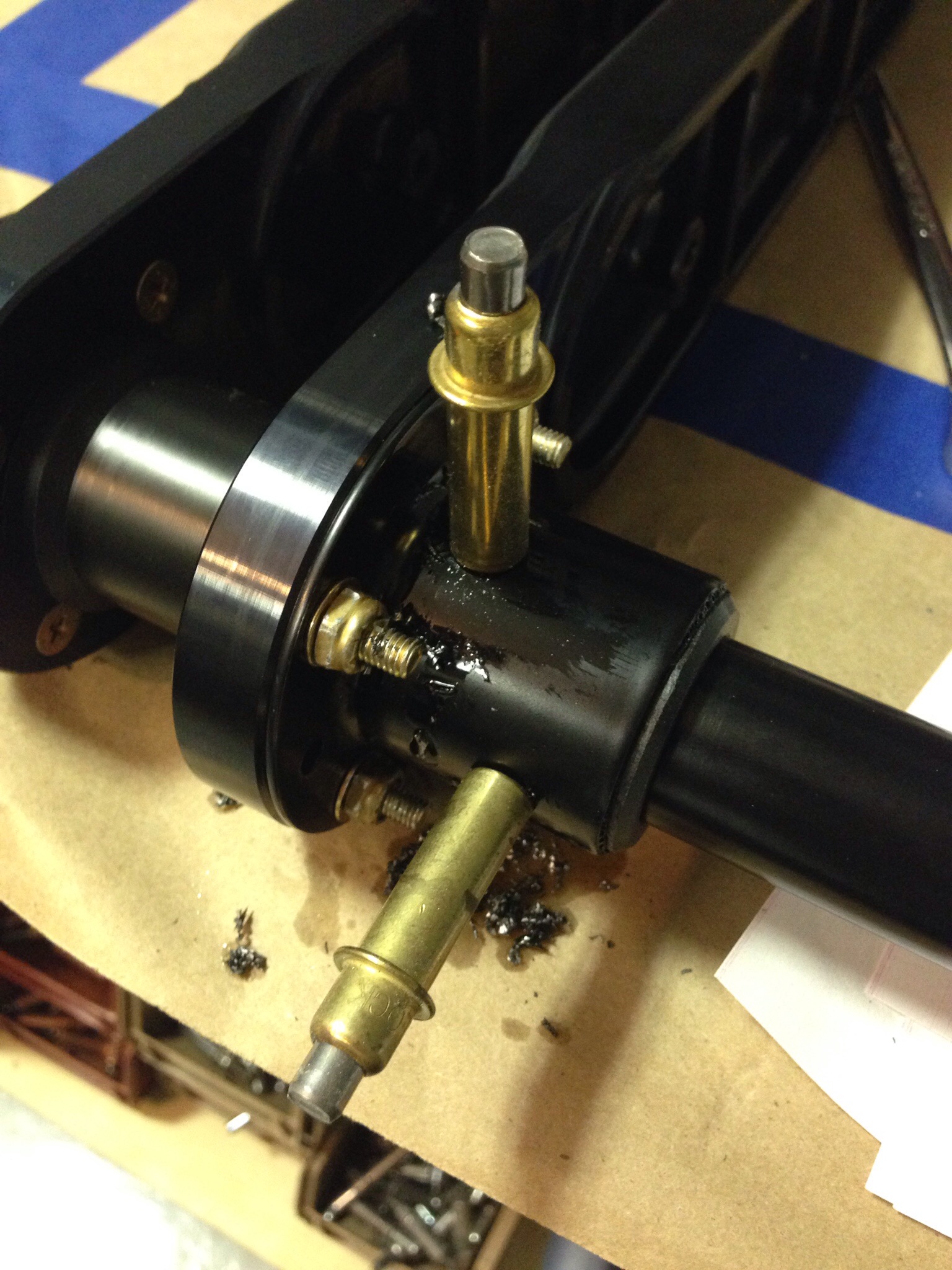
The only hiccup came when working on the elevator trim cable. The original builder had installed the plastic snap bushings the trim cables run through while building the stab. Unfortunately, he put the wrong size bushing in one of the holes that was buried in the spar. The cable wouldn’t pass through. Fortunately the hole was the correct size but man was it a pain in the ass and fingers getting that old one out of there.
Laura helped me bolt the rudder on next to set the rudder cables up and do some trimming for the rudder trim wires and tail light wires. All easy stuff and its really exciting to see the tail feathers finally get attached.
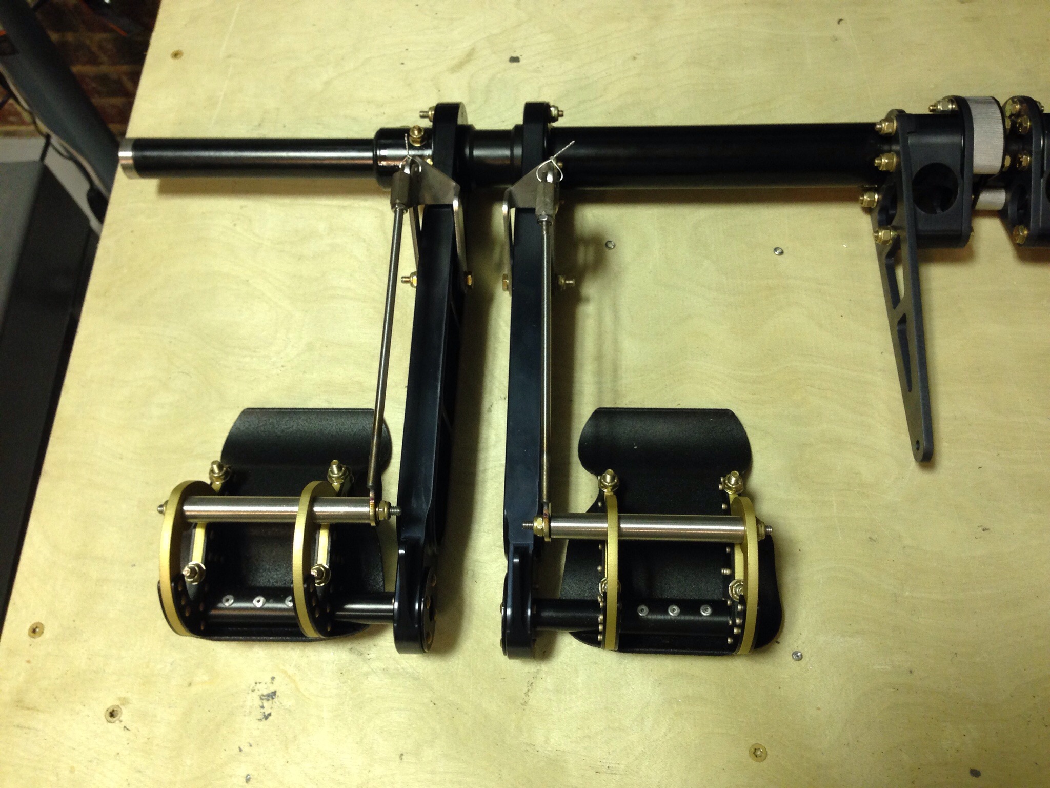
I was able to finally hook up the elevator torque tube after drilling the horns. I was careful to get them lined up accurately and am pretty happy with the end result with the right elevator being lower on the trailing edge by about 1/16″.
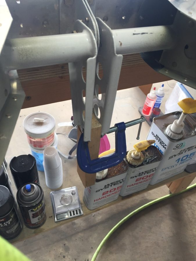
I then set out to start the rigging process by centering the stick and adjusting pushrods to get the control surfaces all lined up. It takes quite a bit of stick movement to get the control range established by the plans and I found some interference with a bolt on the aileron rods under the seat pans. I was able to switch the bolt orientation and it cleared right up.

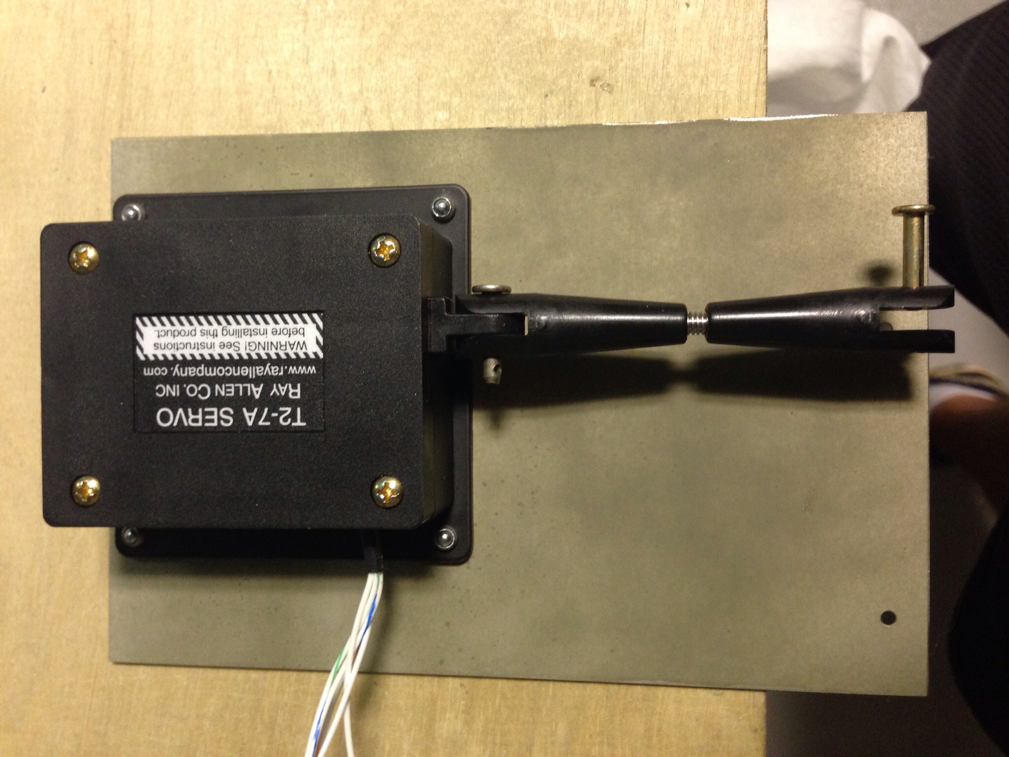
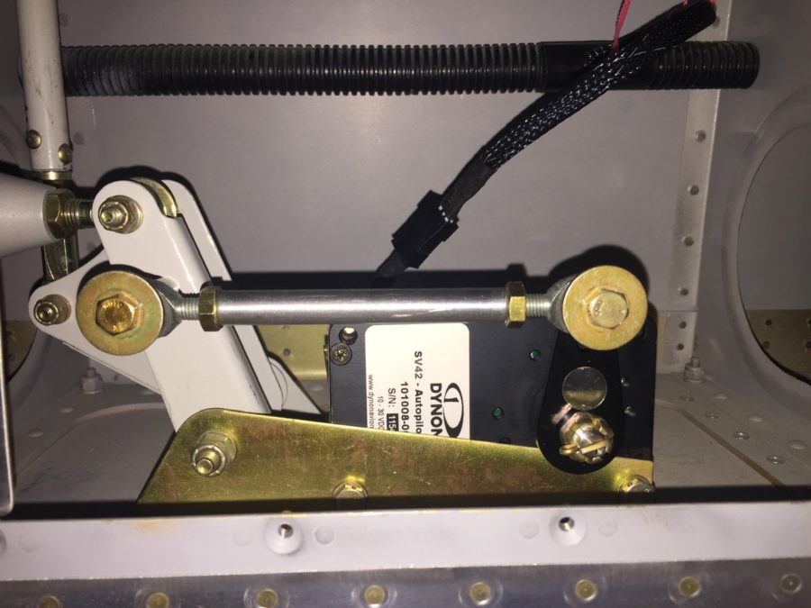
The autopilot roll servo went into the right wing pretty easily as well. I had the mount installed during wing construction, so it was a matter of bolting it in and attaching it to the aileron bell crank. The wiring hooked up quickly since I had already ran the wires and installed a connector.
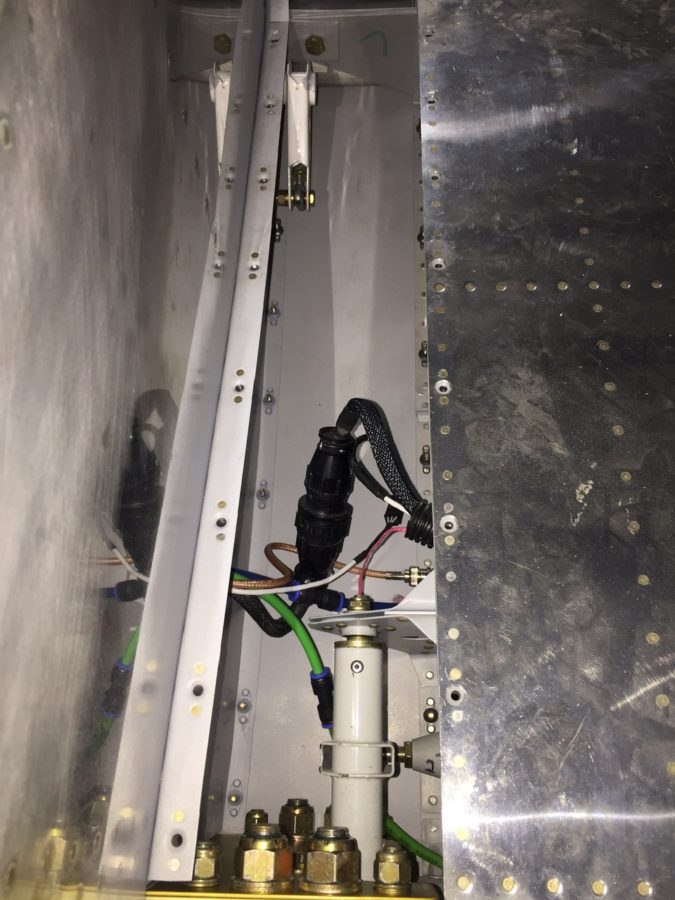
I cleaned up a bit of the wing root area as well, hooking up the CPC connectors, pitot/AOA tubing, and ensured it all cleared the control rods inside. I had planned to mount a bracket holding the CPC and pitot/AOA tubing somehow, but the whole bundle is so stiff, I’m not too concerned with securing it further. It’s also well clear of the torque tube despite the appearance in the picture.
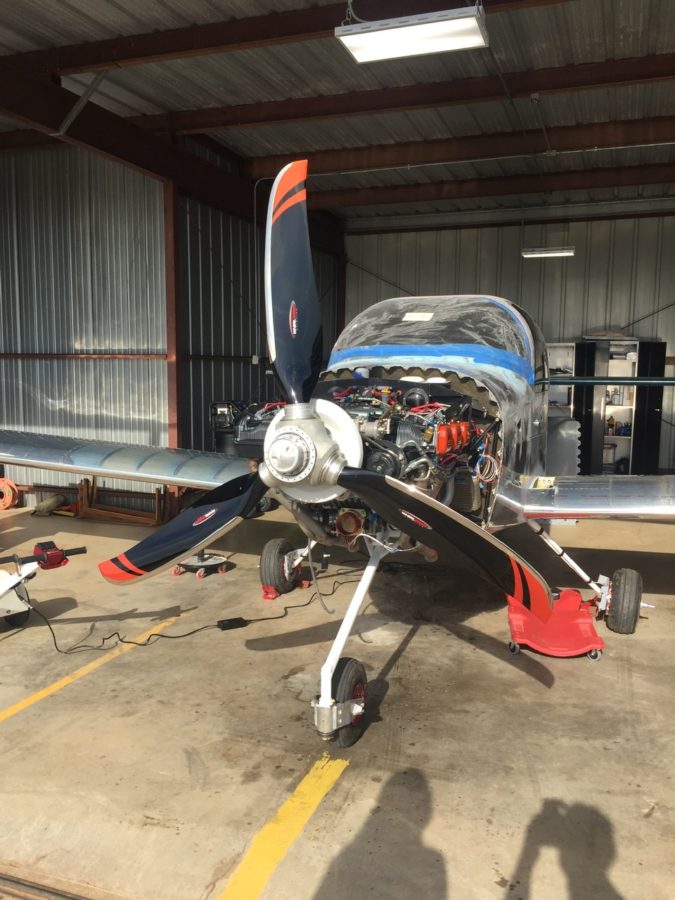
Finally, we had some good light from the sun on the propeller and I couldn’t help but drool over it for a few minutes. The orange over black with the polished leading edges are just too damn cool looking. The scimitar shape is sexy too!
One F*&$#ng Bolt

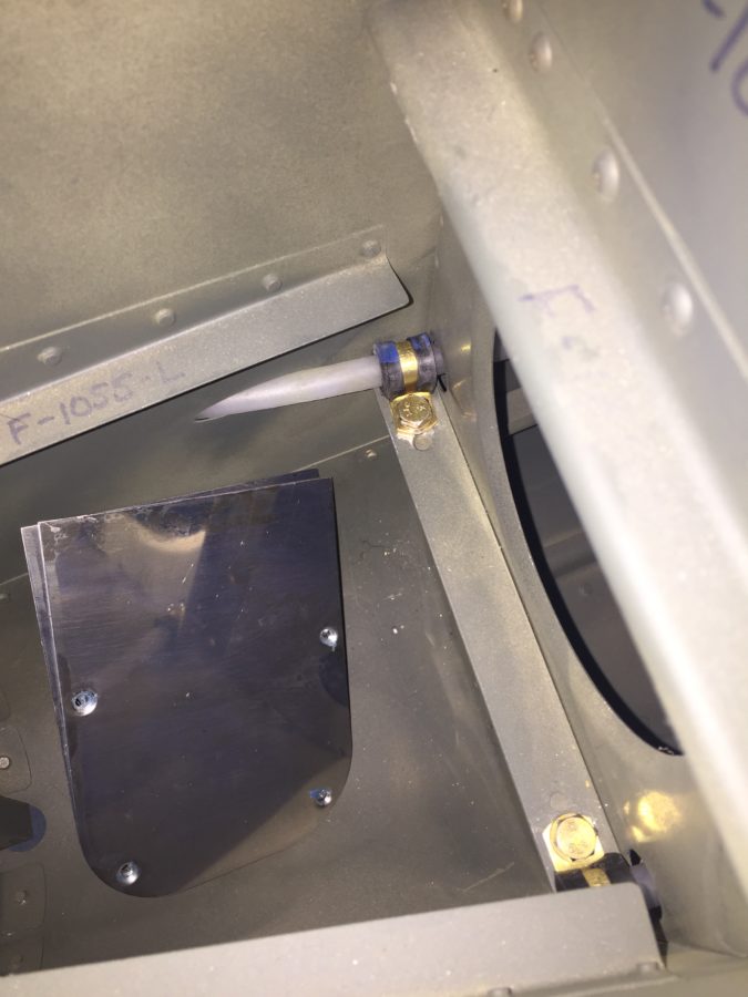
Even though I don’t have the stabilizers mounted, I need to run the rudder cables so that I can start putting other components in the tunnel and move forward with systems layout.  The rudder cables get threaded through the tail cone skin and forward.  Unfortunately, the ends don’t fit through the snap bushings easily and will require me climbing into the tail cone to thread through the bulkheads.  More on that plan later.  I could, however, go ahead and clamp the plastic tubing to the fuselage using cushioned adel clamps where the cables exit the fuselage.  What should have taken about three minutes to put a clamp on and secure it with an AN3-5A bolt wound up taking over 30 minutes and resulted in a lot of frustration.  The clamp proved to be just springy enough that the threads wouldn’t engage and it’s already a tough spot to reach.  With my patience running out and my fingers sore from messing with the bolt, my gut instinct to scream profanities targeted directly at the airplane proved successful and I was finally able to get the little bastard in.  I will never, ever, ever take that bolt out.

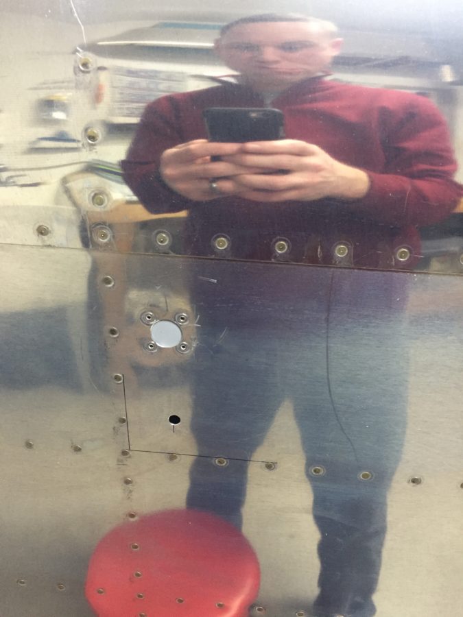
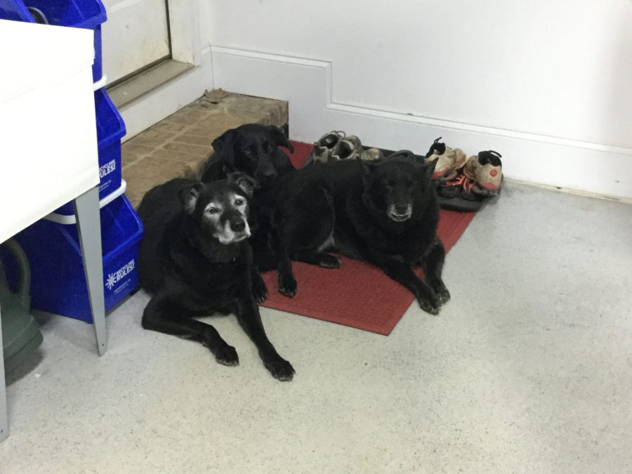
Needing to lower my blood pressure and calm my headache not to mention my now very concerned shop dogs, I decided to move to another aircraft system, the pitot static system.  I ordered a kit from Safe Air 1 quite a while ago and have already installed the pitot tube mount with preliminary tubing in the wing.  When I built the tail cone, I used another brand static ports that after looking at for years had to go.  The Safe Air 1 ports are designed to be mounted from the inside and have a very clean look not to mention good reviews of functionality.  Since I was going to have to crawl in the tail cone anyway, I decided to remove the current ports to prepare for the Safe Air 1 version.  I had to drill out the four rivets, clean up the holes, dimple them, and make a patch.  The patch is required since the original ports had a half inch hole required.  I had to get pretty creative on how I dimpled the holes since I can’t get the pliers or squeezer on it.  I wound up using the blind rivet nail trick with the dies designed for a finish nail with great results.  Once the patches were made, I used blind rivets that sit nicely in the skin for ease of use and negating one more task of bucking rivets while crawling in the cone.  Since I’ll use flox filler to smooth out the hole anyway, the blind rivets will disappear.  I’m really happy with the result and quickly relocated the new port hole just below the original location.  I don’t anticipate any issues with the new location.

I also installed the avionics shelf that I had fabed previously with the proper spacers and screws.  I plan to use nutplates for permanent mounting of components once all of the boxes are laid out.  I’m preparing everything I can think of to do while crawling in the tail cone to include mounting the new static ports, mount the static line and clamps, route the rudder cables, install snap bushings for tail wiring, and run string to pull future wires.

Service Bulletins

While having some down time at home that I can’t do much productive anything with, I decided to research quite a few things while lying in bed after surgery.  One of those was service bulletins.  There are a handful out there for the RV-10 and are a lot like AD’s issued by the FAA, but they are not mandatory by law.  Highly recommended, however, so in the home built world, you comply with them.  With this being a build log, I wanted to document them here and then I’ll make the associated entries in the air frame log book once I have one.

The empenage kit (oldest original kit) was delivered in October 2005 to the original builder, thus I have only addressed those SB’s relating to the dates affecting our kits.

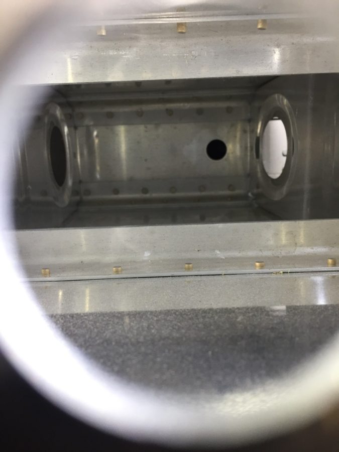
SB 06-2-3 is for the vertical stabilizer rudder mount.  This SB was completed by the original builder and complies with all aspects of the SB.  I could not get a good picture inside a tiny access hole, however, visually confirmed the doubler plate is in place inside the main spar of the VS.

SB 06-9-20 is for the trim cable anchor nut on the elevators.  While our kit does have the double welded nut, I chose to upgrade to the CNC machined piece by IFLYRV10.com.

SB 08-6-1 is for the F-1010 bulkhead near the vertical stabilizer in the tail cone.  My kit came with the SB contents and I completed it as part of the original build of the tail cone.

SB 16-03-28 is for the aileron hinge brackets possibly cracking on the inboard aileron mount.  I have removed the portion of the gap fairing to allow future inspection and no further action is needed until flying, at which time an annual inspection of the bracket must be made and noted in the log.

There are other SB’s that will affect our build, however, I have not gotten to that stage of the build yet, so will cover it in another post.

Control Approach to my rudder pedals

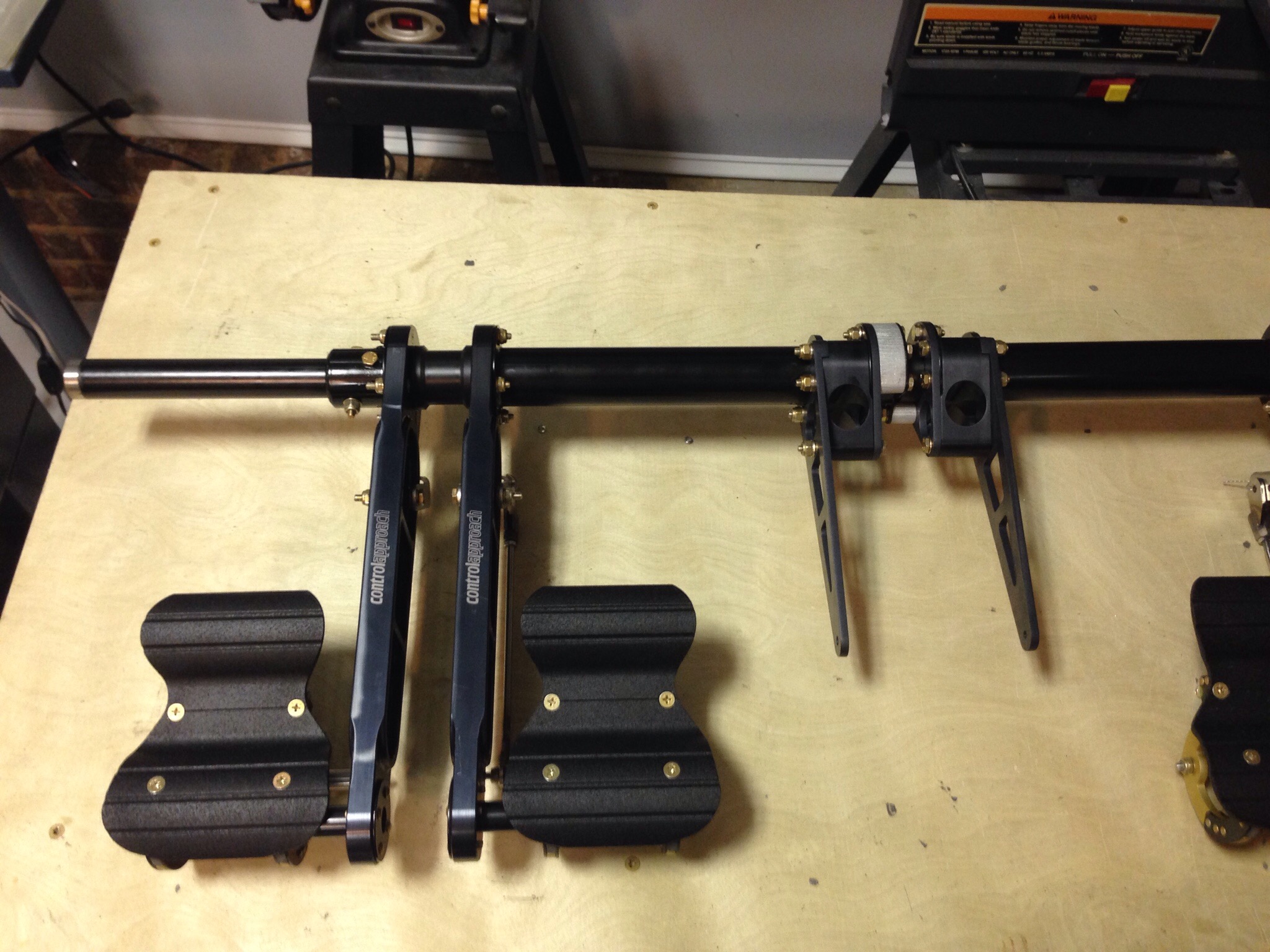
RV-10 builders have drooled for years over ControlApproach rudder pedal set up and I am no exception. A few lucky guys picked up the available sets and Paul hasn’t produced them for a couple of years. I always kept an eye out for the classifieds for a set but had no luck. I decided to take matters into my own hands and reach out to Paul directly.

As luck would have it, Paul was filling promises and had a small production run with one set left. I weaseled my way onto the list and within a few days, had a set on its way to my house.

These pedals first of all look amazing. The design is much better aesthetically then the Van’s setup and goes along way to making the aircraft interior look professionally done. They are also awesome functionally, feeling much better (in my limited experience, one flight with and one flight without them) especially with the free-castering nose wheel on the 10. They relocate the master cylinders to the back of the pedal arms to clear up some foot space and eliminate hitting them with your shoes. They also move the rudder cables to the tunnel for their entire run.

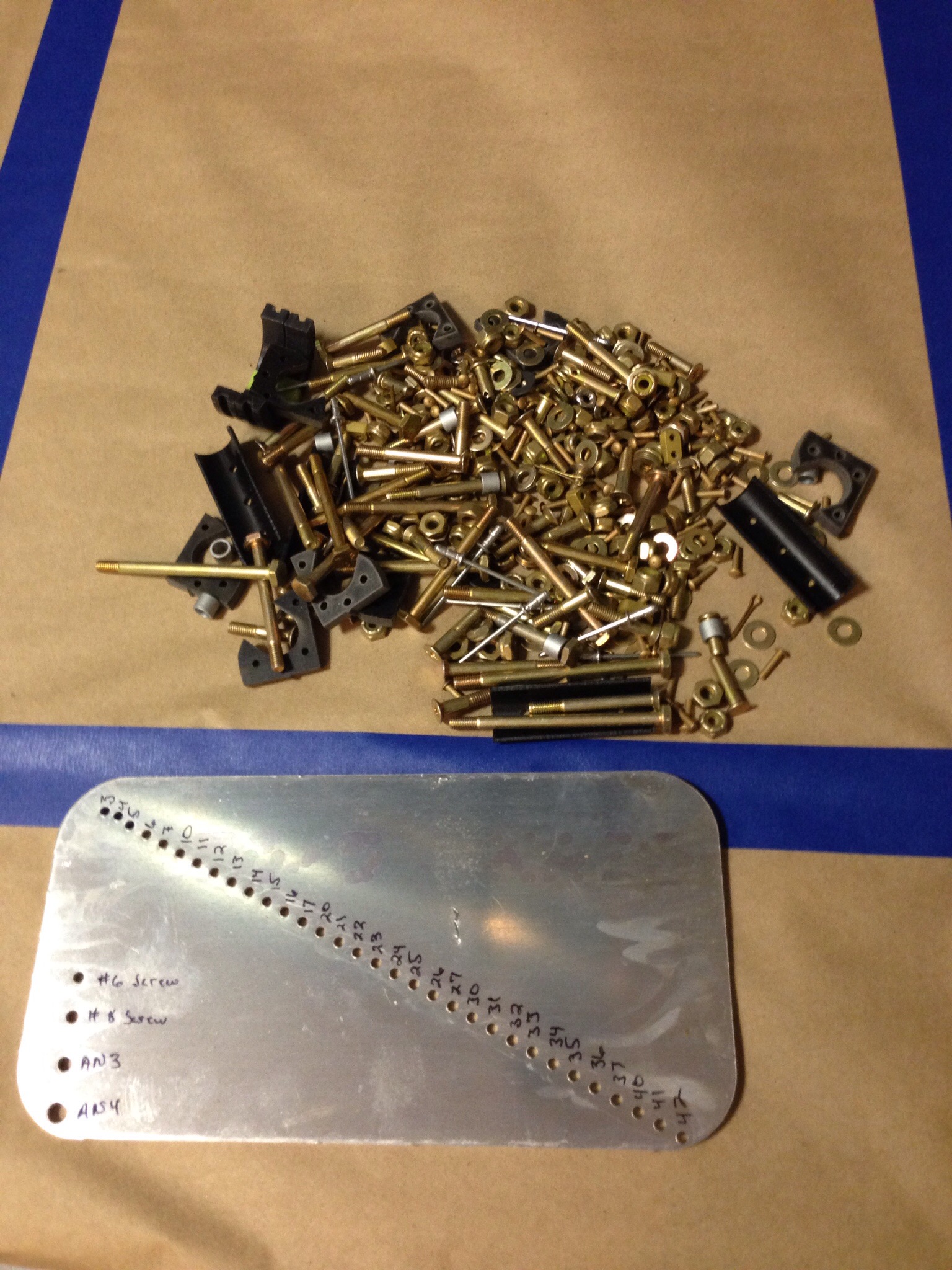
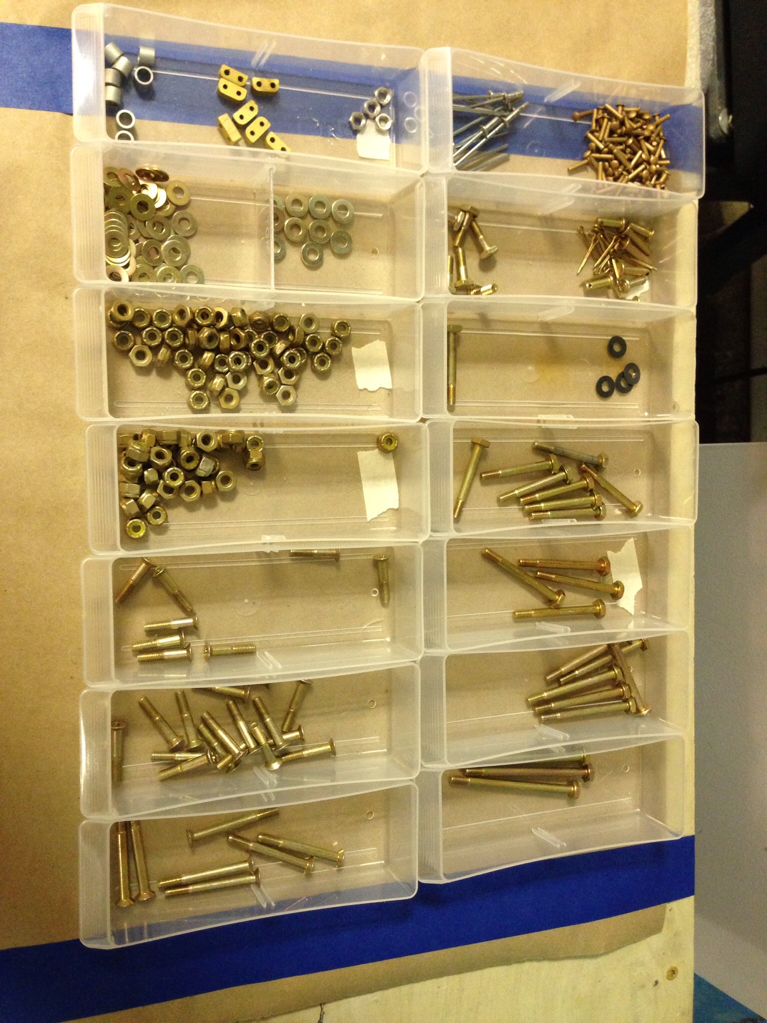
While the machining and quality of the pieces is amazing, the directions leave a lot to the imagine. The box was well packed but the hardware bag was a bit intimidating!

IMG_1419.JPG
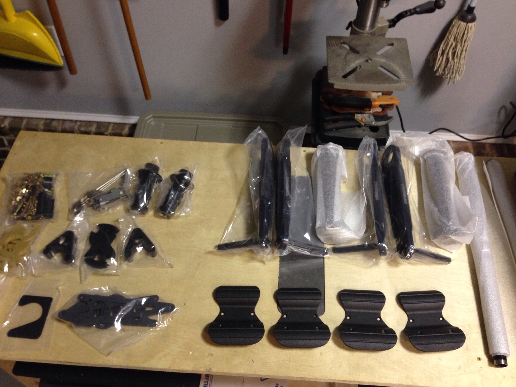
After a bit of organizing, it was much less messy and I was ready to get to work.

IMG_1420.JPG

IMG_1416.JPG
I had to re-read the directions a lot, but once I got a start and all the pieces laid out, it makes sense. A bit of jigging was required to get the four holes drilled for the inner and outer tubes that linked the pilot and copilot pedals.

IMG_1421.JPG
There is also a shortage of thin washers with the hardware kit, but I fortunately have plenty in reserve and most that I need are needed when installing the master cyclinders. I put everything together and securely stashed them away in the storage racks until ready for the fuse.

IMG_1425.JPG

IMG_1424.JPG

Just a little trim

With the rudder complete according to the plans, it’s time for me to venture off into experimental land for the first time in the build.  A lot of other 10 builders are putting an electric rudder trim in and I want to do the same thing.  There are some great write ups on other’s build sites that I borrowed most of the ideas from and then just tweaked to make my own.

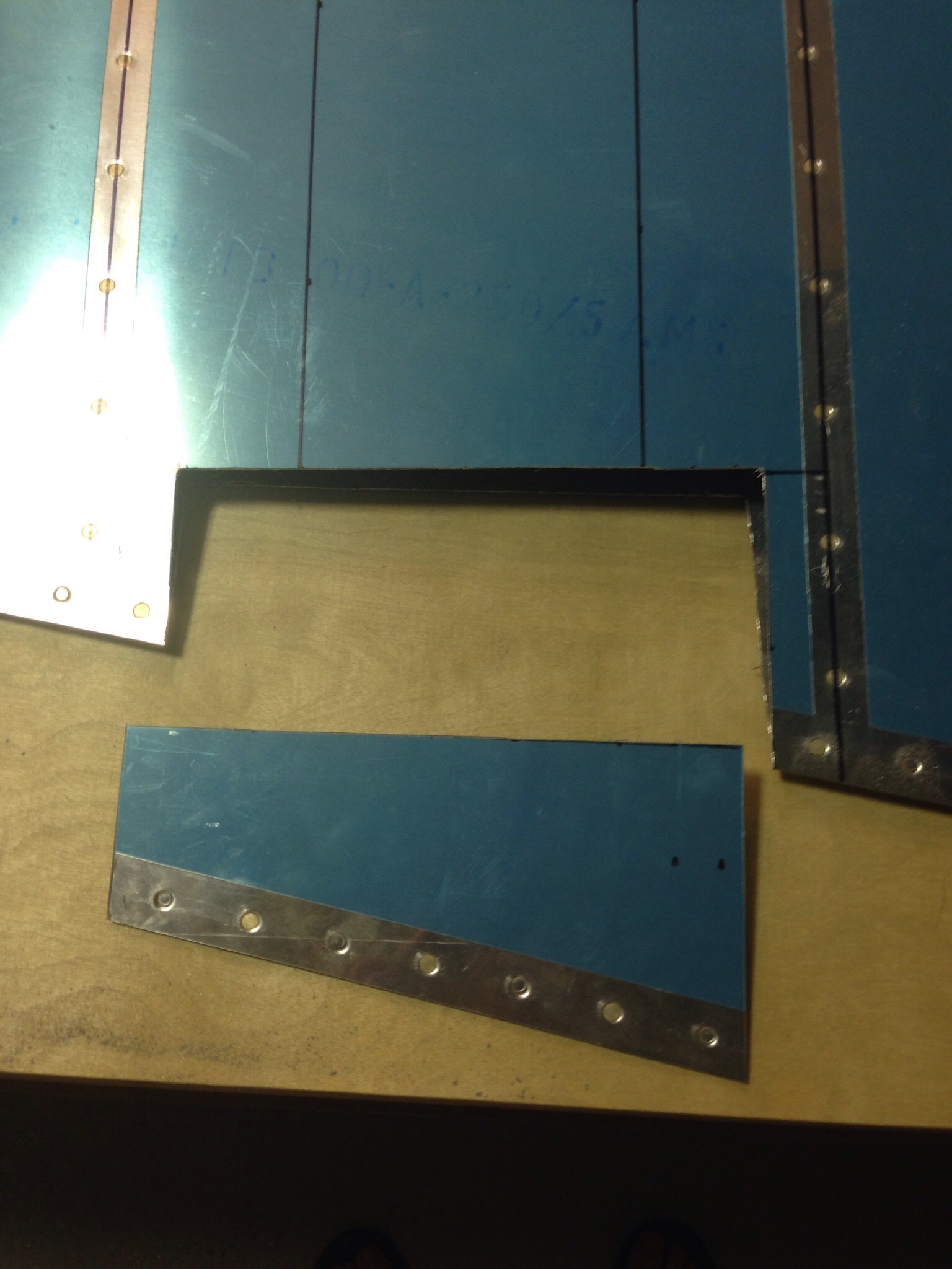
I started by laying out where the trim tab will be on the rudder.  I didn’t want to add any structure outside of the rudder, so I’ll be cutting a tab out and hinging it.  I choose the vertical mid point between two ribs for the location.  I then measured out the tab based on very scientific eyeballing and comparing to others.  I made sure to keep it centered and spaced evenly between the ribs and also to keep the hinge line perpendicular to the air flow.  Once copied to the other skin, it’s time to break out the Dremel and start stressing about making the cuts right.  It wasn’t nearly as bad as I thought it would be.

IMG_0149.JPG

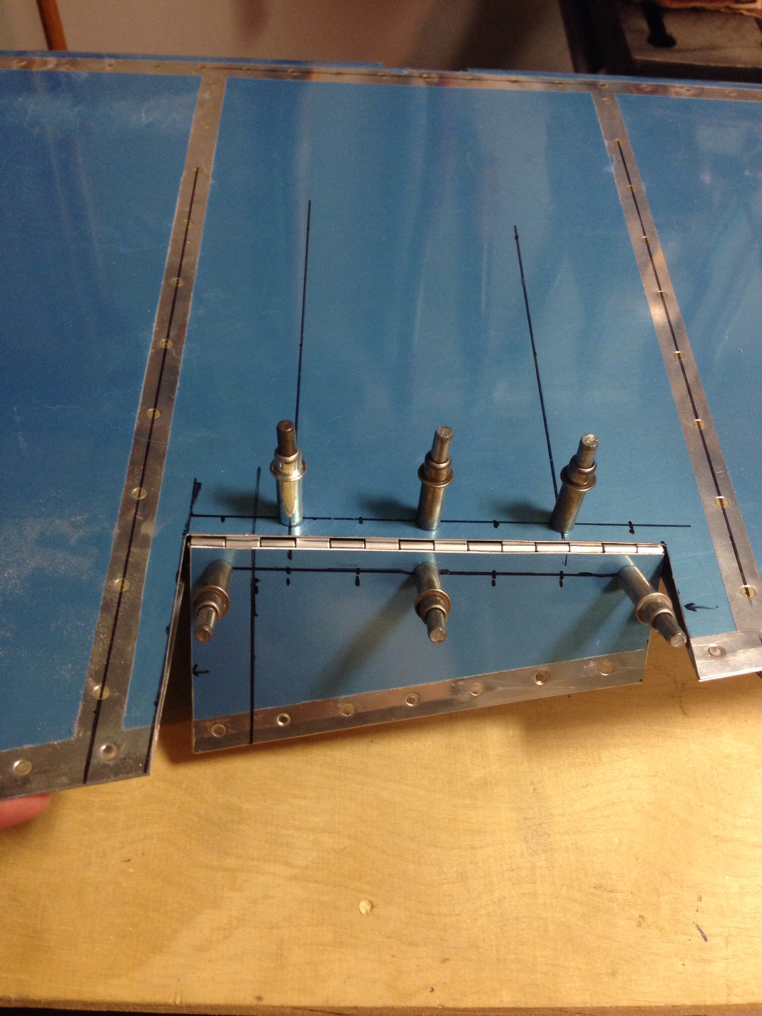
The hinge was next coming from a stick of piano hinge from Aircraft Spruce cut to size.  A main goal is to make it as drag resistant as possible, so I put the hing on the left inner skin which allows more movement to the right and a minimal gap when it is trimmed to the right (which is where it will spend most of its life).

IMG_0152.JPG

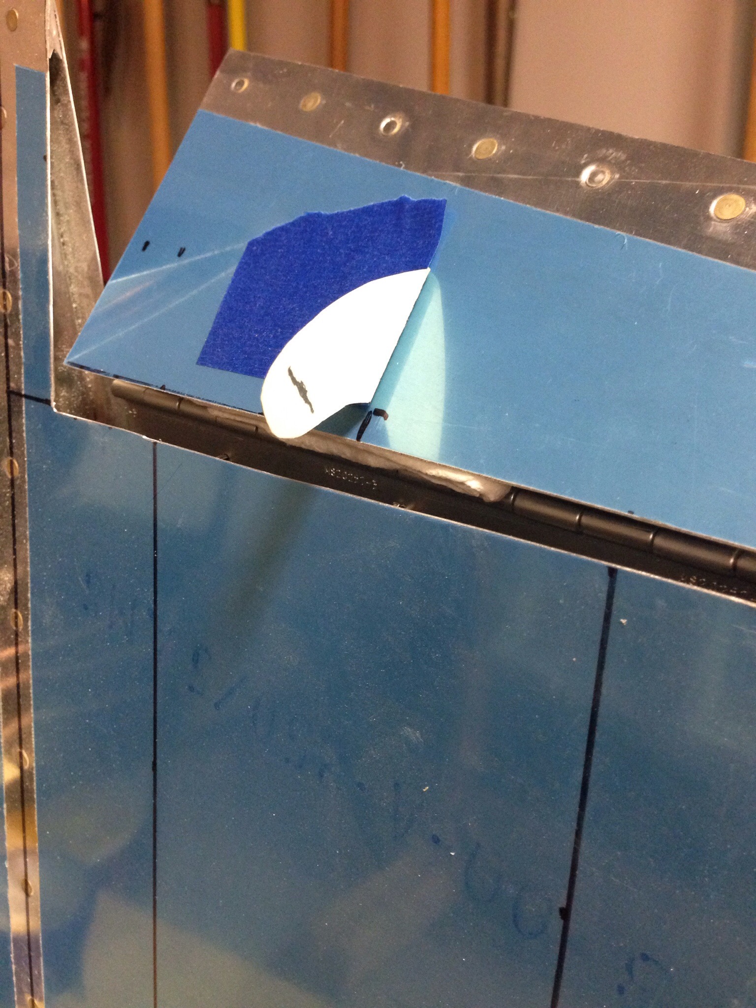
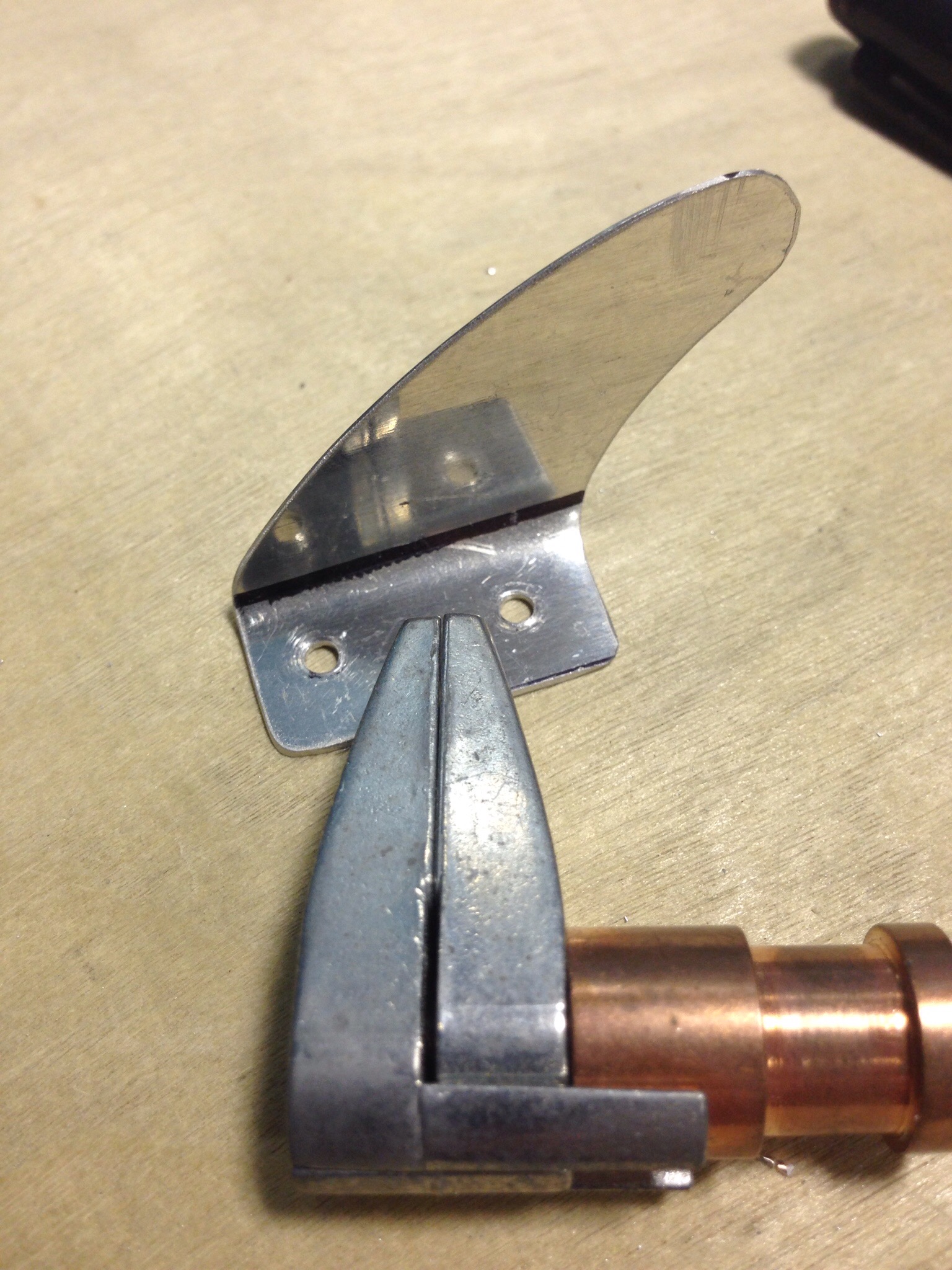
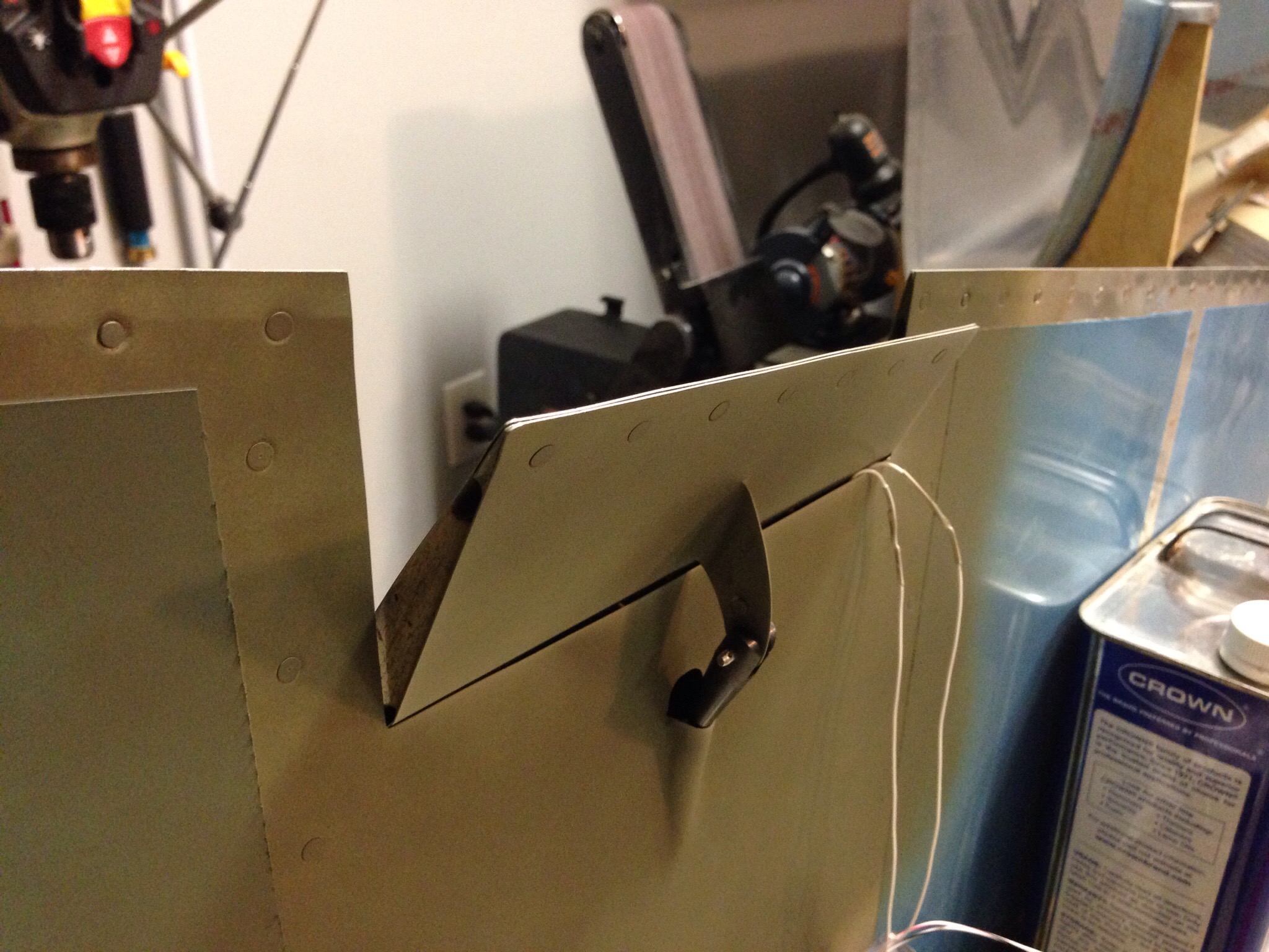
Next step was to create a mounting arm for the servo rod.  I started with a piece of manila folder to get the shape close.  This is where all my experience with RC models really paid off, as the system is very similar to any RC plane or helicopter set up.  I then cut two pieces of aluminum trim to the curved shape and bent the tabs in opposite directions to mount onto the trim tab.  Again, to minimize drag and maximize coolness factors, I cut a slit for the servo arm to slide through so I could have the mounting tabs inside of the tab.

IMG_0154.JPGIMG_0156.JPG

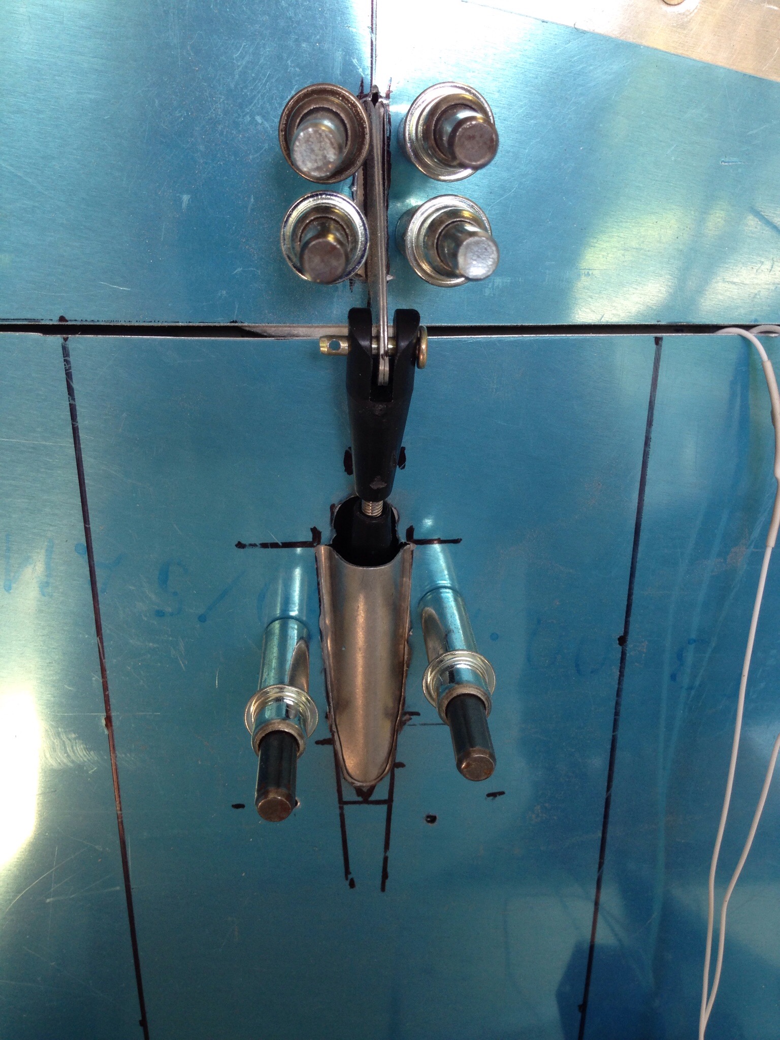
Rather than have an inspection panel with the servo mounted to it, I used another idea of having a piece of aluminum trim mounted to the hinge which serves as a base for the servo.  This way, I can remove the entire trim tab system, servo and all, from the rudder for maintenance using a minimum number of screws.  It’s also a little cleaner looking in my opinion.

IMG_0157.JPG

A rudder cable fairing finishes it off, again mounted from the inside and finished with a little micro and epoxy to smooth things out and cover the rivets.

IMG_0161.JPG

I trimmed a couple pieces of left over Styrofoam from the elevator trim tabs to epoxy in and keep the shape / provide structure for the tab.  I finished it off with a little micro to seal it all up.  The leading edge (non-hinged) was bent inward to create clearance for travel.

IMG_0165.JPG

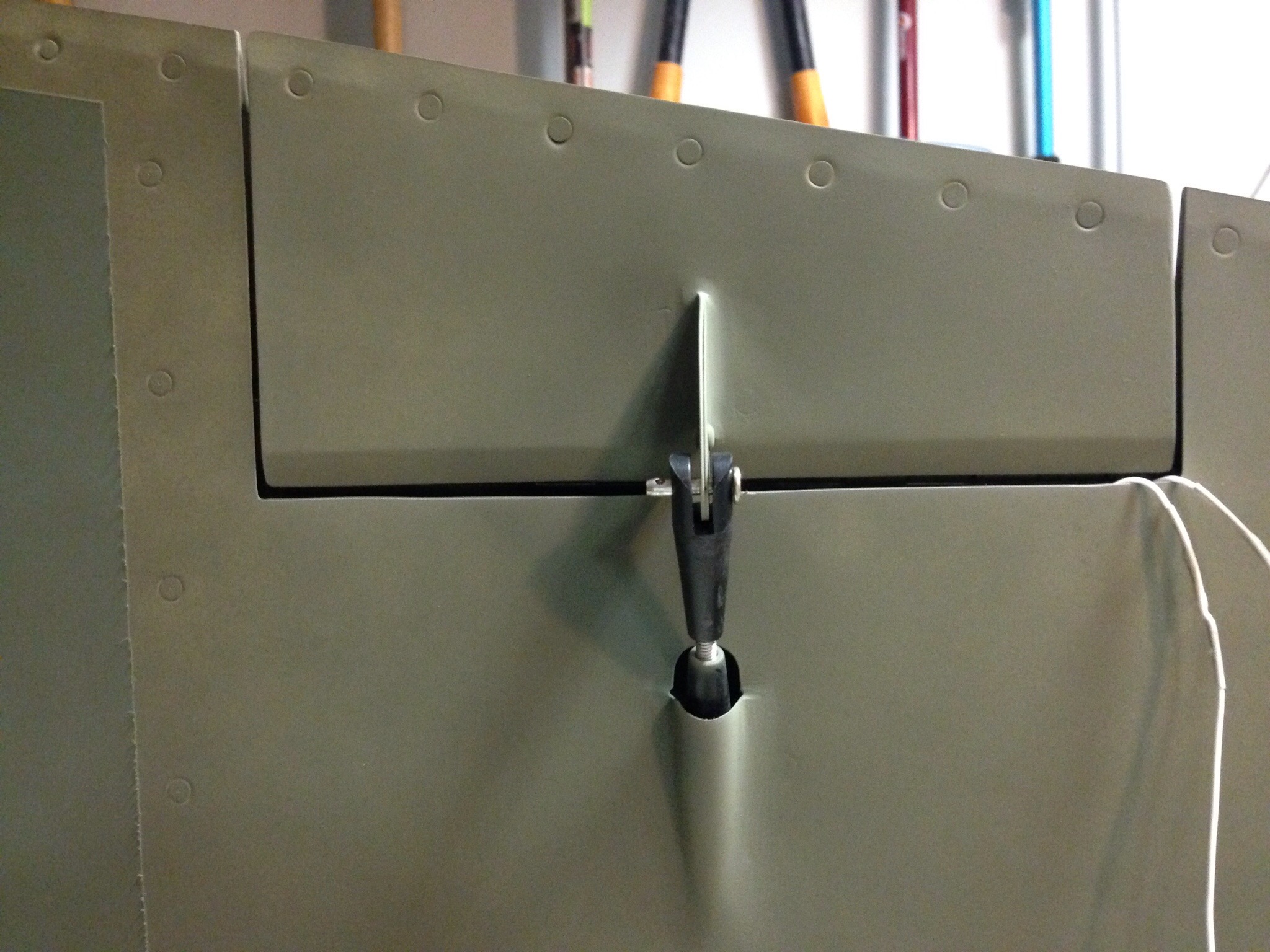
Overall, I’m very happy with the end result and it was a pretty easy project once all thought out.  I’ll hook up the wiring connector later in the build.  I did test it and get a pretty fair amount of travel.  Based on other’s I saw at Oshkosh, this will be more than enough trim power for the 10 even during full power climbs.

IMG_0168.JPG


I don’t like that color

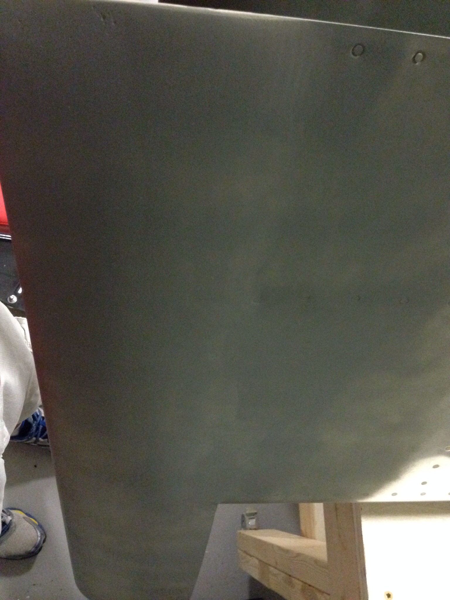
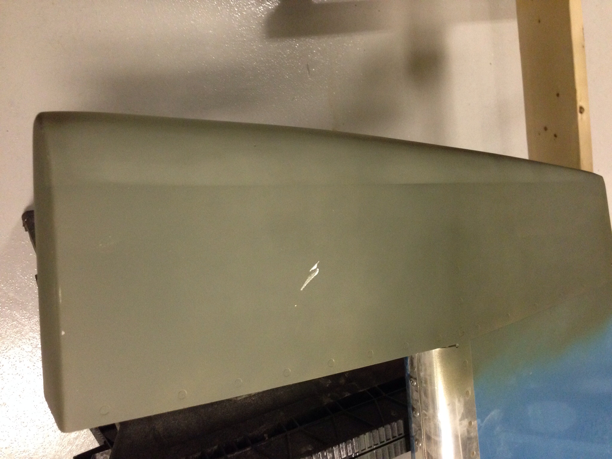
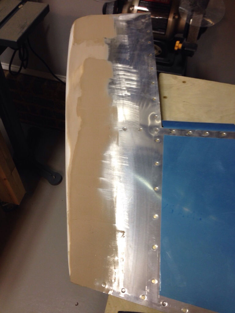
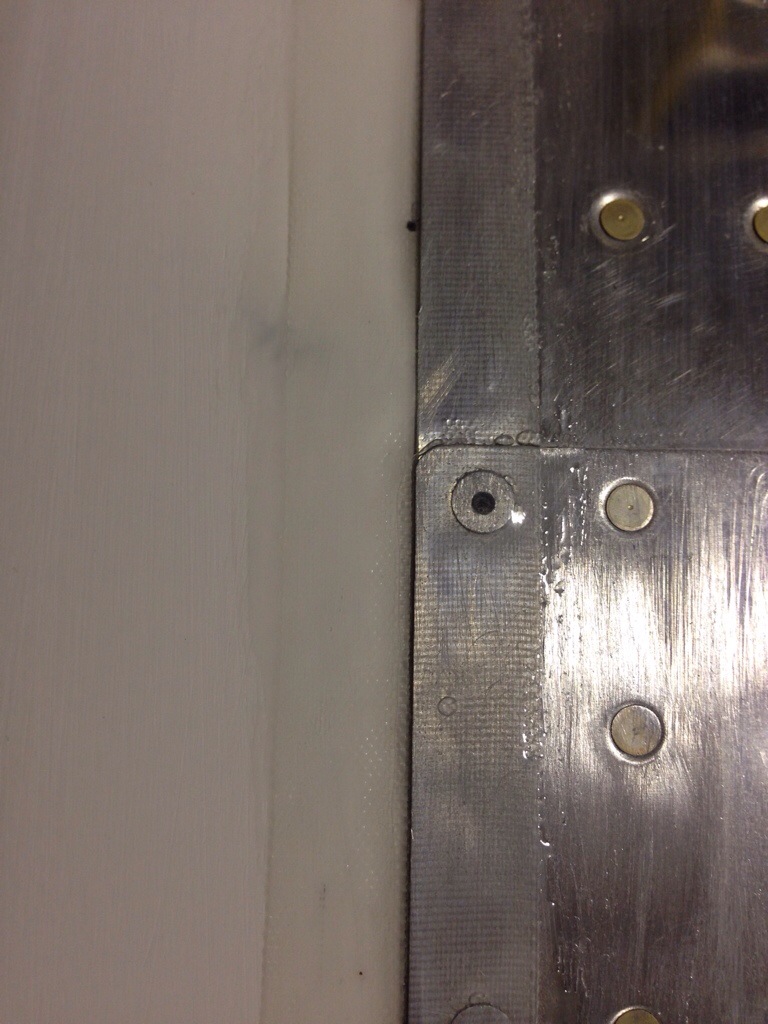
I have had enough sanding for a while and figure it’s time to throw some primer on top and see what the results are on the control surface tips.  I was pleasantly surprised how good they turned out.  The sanding really paid off and with the few pinhole exceptions, the transitions between the fiber and the aluminum are very smooth.  The primer is an ugly color, but at least it highlights where you still need work.
IMG_1010.JPG
I was especially excited about the top of the rudder where I had to add a lot of fill to make it nice and smooth.  The micro added to the West Epoxy is solid as a rock when cured but still sanded pretty easy.  Really easy to work with.
IMG_1011.JPG
So the elevators are complete now and went back up on the wall.  I have just the bottom rudder fairing joint to smooth out and then I’ll start on the rudder trim.

Creamy peanut butter

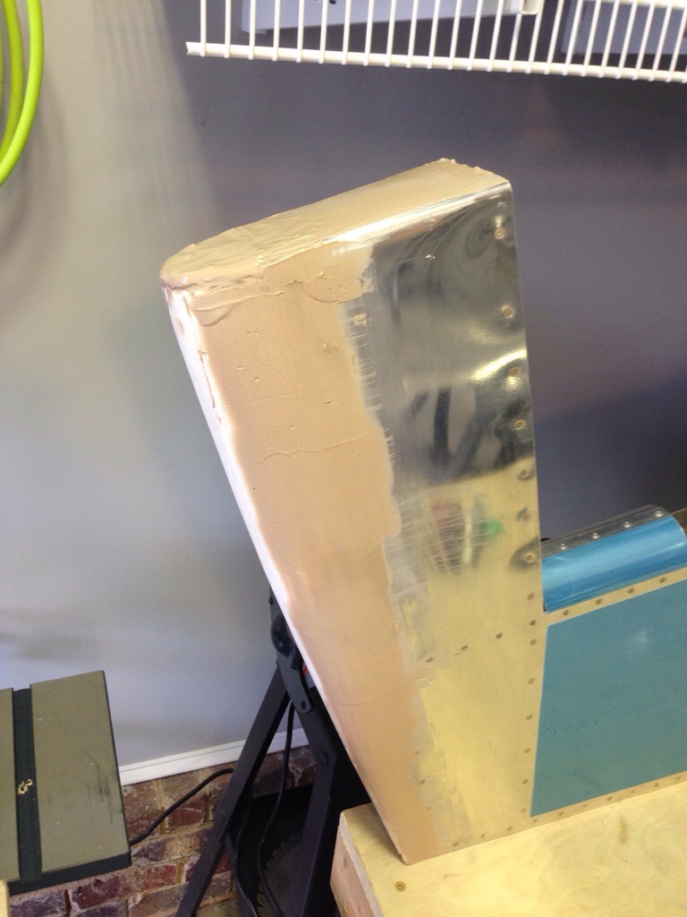
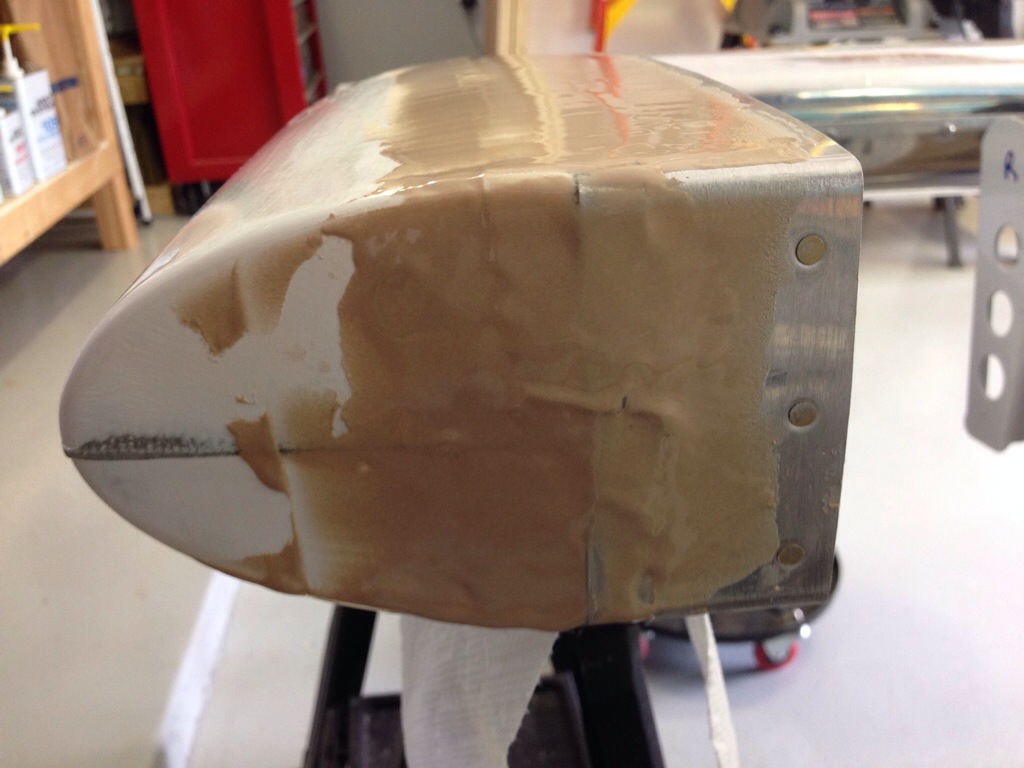
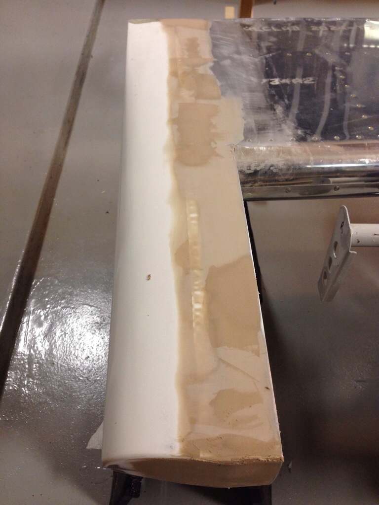
After the epoxy set up on the fiberglass tips, it was time to put on the filler, often referred to as micro, to smooth things out.  I’m using the West epoxy system and the 407 filler.  It’s an extremely fine powder that is a tan color and according to others very easy to work with.  You mix up the epoxy as normal with a 5:1 ratio and then add in the filler to get a consistency of creamy peanut butter.  Then just spread it on and smooth it out as best you can then wait for it to cure.

I’m not a stranger to using Bondo, dry wall mud, and other fillers, but I still have a few lessons learned from my first experience on the plane.  First is when mixing the filler, you want a really think peanut butter mix, not creamy.  My first batch ran and settled a little too much, requring me to position the pieces so it wouldn’t drip.  Keep in mind it takes a few hours for the slow hardener to set up.  If you have a lot to add to build up, make it as dry as you can.  Second, follow Ron Propeil’s advice and set it and forget it.  Just like dryway, the more you mess with it, the worse it gets.  You won’t get a perfectly smooth application so stop trying.  That’s what sand paper is for!  Third, is patience which I do actually have for this.  One coat is seldom enough to smooth out whatever your working on.  Go in stages and don’t try to build Rome in a day.

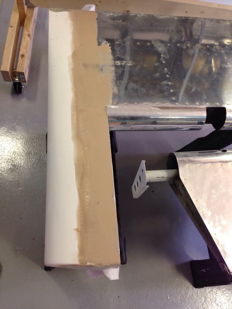
Thus, my first coat was pretty successful.  I scuffed up the newly laid fiber and made sure the aluminum was scuffed with a Scotchbrite pad.  Then clean everything with thinner and apply the filler.  I filled in a lot on the tips’ leading edge where it didn’t match up with the aluminum well.  I was also excited that it actually set up well!  I have a fear of mixing the epoxy wrong and it just being a goopy mess.  The pump system for the West epoxy is a must have.

20140723-163616-59776751.jpg20140723-163615-59775937.jpg

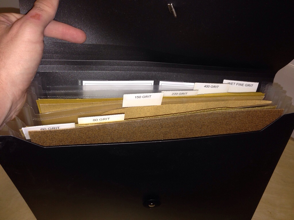
Next, you get to break out the sand paper.  And a lot of it.  A couple lessons on this too. Have a variety of grits; I used 80 to knock off the big ridges and bumps, then 150 to contour, and 220 to smooth it all out.  I found that the 150 really didn’t work too well as the dust would bond to the paper and clog it up.  The 220 worked great and lasted a long time.  I have a couple of different blocks that are working well.  I’ve read never to use your fingers since they will not sand uniformly, but there are always a few spots that the block can’t get.  Make sure not to sand too much off.  It’s better to get it close and put another thin layer of filler on to really smooth it out.

I put the second coat on a bit dryer than the first and that was good for the big spots, but also harder to get a smooth application.  For the finish coat, it’s better to have it a bit creamier so it will apply smoothly with no pinholes.  The second coat was sanded with 80 and then 220.  You can tell if you have low spots by the different color when sanding which is nice.  Never sand out a low spot.  Add to it then smooth it out.  Blow off the dust, clean with thinner, and repeat the application process.  This is the third coat and I’m pretty sure it will be enough.  The corners are still hard so I gooped it on and will sand it smooth.  I’m hoping the other side will go faster since I’ve got some experience under my belt.  I’ll finish it all with a 440 grit before doing some quick primer and reevaluating.

20140723-163618-59778462.jpg20140723-163617-59777588.jpg20140723-163621-59781023.jpg

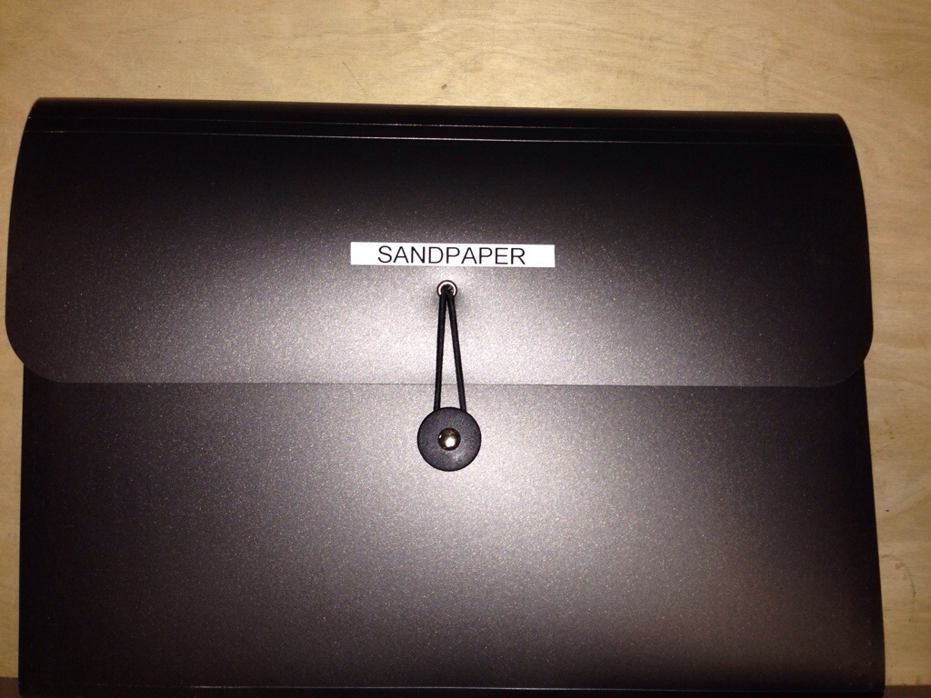
And of course, you have to have things organized.  So to keep all this sand paper (I have more than listed), I got a cheap expanding folio at Wal-Mart Aviation Supply and threw some labels on it.  This works perfect and keeps it all in one spot.

20140723-163619-59779322.jpg20140723-163620-59780179.jpg

Here’s a tip for you.

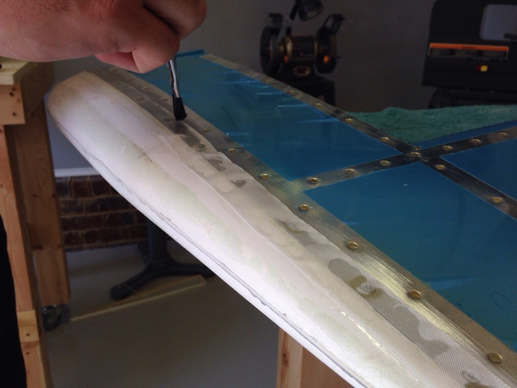
Fiberglass is very daunting to some while no big deal to others.  I’m in the middle.  I don’t like sanding for ever, but it’s a nice change from deburring.  The tips of the control surfaces and both wings and stabilizers all are made of fiberglass and get riveted onto the aluminum.  While the plans call for that the to the end of it, some builders will put a layer of glass over the joint to seal the gap, improve aerodynamics, and improve the look.  Since I have plenty of time, I decided to do the same.

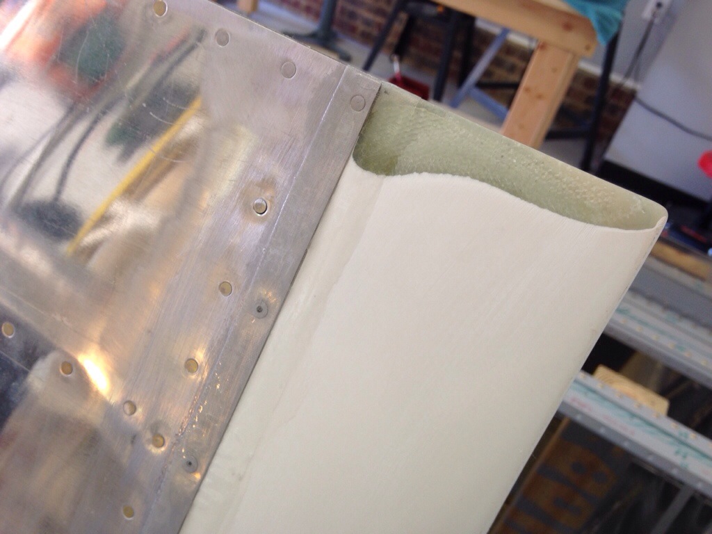
First step is to test fit the pieces and notch out around the trailing edge.  I also needed to cut a bit off the flange so it would fit flush under the skin.  Overall, these are formed pretty terribly next to the aluminum but they are old and I’ve heard Van’s molds are better now in newer kits.

20140717-163106-59466163.jpg

After fitting, I drilled and countersunk the fiberglass while dimpling the aluminum to take the pop rivets.  This was pretty straight forward and the only exception I will make is to put nut plates and screws on the bottom rudder fairing so I can access the nav light.

20140717-163105-59465736.jpg

The first step in glass thing joints is scuff the area with 80 grit sand paper so the resin has a bit more bite surface to it.  I then mixed up the West Epoxy system with the slow hardener and painted on a thin coat.  I used a 1″ glass strip cut to size and laid it on the wet epoxy.  Others have done more than one layer, but I plan on sticking with just one.  Make sure that all the fabric gets soaked and minimize the excess then just let it sit.  I did apply a bigger piece on the leading edge of the rudder tip since it was formed shorter than the aluminum structures.  I’ll layer one or two more times to build up the difference then fill this with micro and create a nice smooth surface.

20140717-163106-59466983.jpg

The trailing edge cut required a bit of sanding down to match the profile of the elevator.  I used my belt sander which worked really well as long as I was careful to watch the shape and amount taken off.

20140717-163106-59466572.jpg

This is the final result of the first glass laid on the project.  I’m pretty happy with it.  Next step will be some sanding and then a layer of micro to smooth it all out.  Sand and repeat, I’m sure.

20140717-163107-59467415.jpg

First Inspection

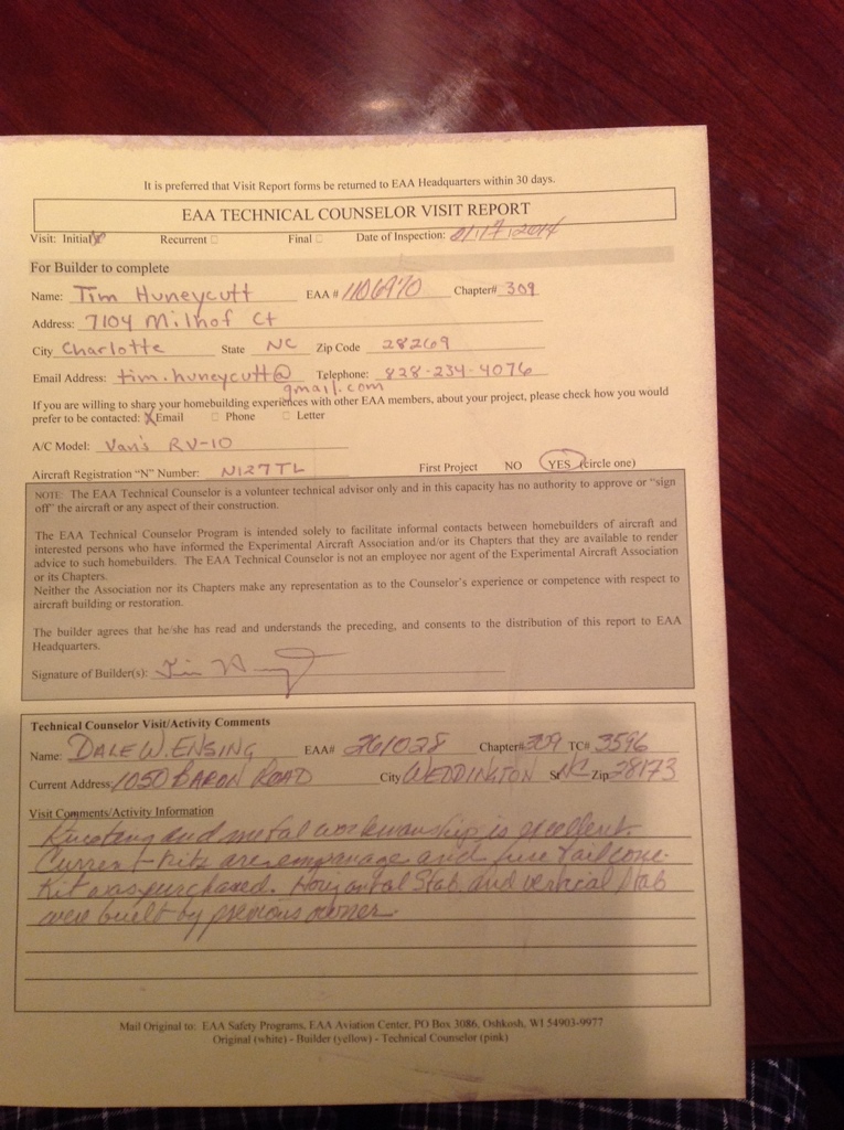
The project got it’s first inspection today when the local EAA Tech Counselor, Dale Ensing, dropped by to take a look at my work. I wanted him to critique my build early on to ensure that I was on the right path and correct any bad habits before getting too far into the project.

As typical, the visit turned into swapping stories and sharing experiences, all of which something can be learned from. People like him make this rewarding project even more fun. He took a good look at the work done thus far by the previous builder and by myself with favorable comments. The main recommendation he had for me was to go ahead and spot prime the outer skins on areas where I had taken of the surface corrosion. I asked him several questions about priming, rivets, other random build techniques and got some great info and tips from him. Best of all, it was an evening spent talking about our passions for aviation!

With a boost of confidence and a confirmation of satisfactory work, I’m left with a pile of parts once again after disassembling the tail cone. I began stripping the blue film off pieces and will work now on deburring and dimpling. That will all have to wait at least a week, however, as I’m headed up to Greensboro for a week of flying and hopefully my commercial rating!

20140117-215050.jpg

Rudder is all closed up

20131204-212210.jpg

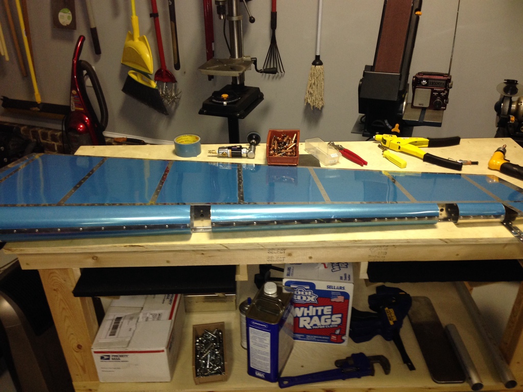
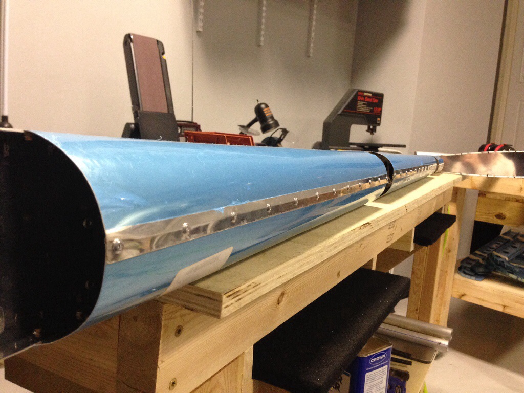
I spent tonight rolling the leading edges for the rudder. Didn’t I say to roll the edges before final assembly? Yes, I did. I’ll have to remember that next time! The process really isn’t too bad. I use duct tape and an aluminum pipe cut down to just longer than the section of skin (I have three different lengths that work well). Once I have it rolled, I use an edge roller to bend both skins inward. I find bending both vs just the top as the plans call for, helps the skins sit flatter once together. Putting them together the first time is the hard part, but is manageable for one person but easier with two. Once clecoed, final drill then uncleco to deburr. Then back together and finish off with the pop rivets.

Despite putting good bends and slight pressure on the rivet tool when setting them, I have a few that still show a space between the skins. I’m thinking about ordering some extra rivets to redo those few and see if I can get a better result. But, overall I’m happy with it.

One thing I continue to be proud of is keeping the shop clean. I replace tools after I use them and be sure everything is put up before calling it quits for the night. Not only does it keep the garage looking good, it keeps me organized and let’s me work a lot faster not having to sift through junk to find what I need.

20131204-212218.jpg