Dirty Door Details

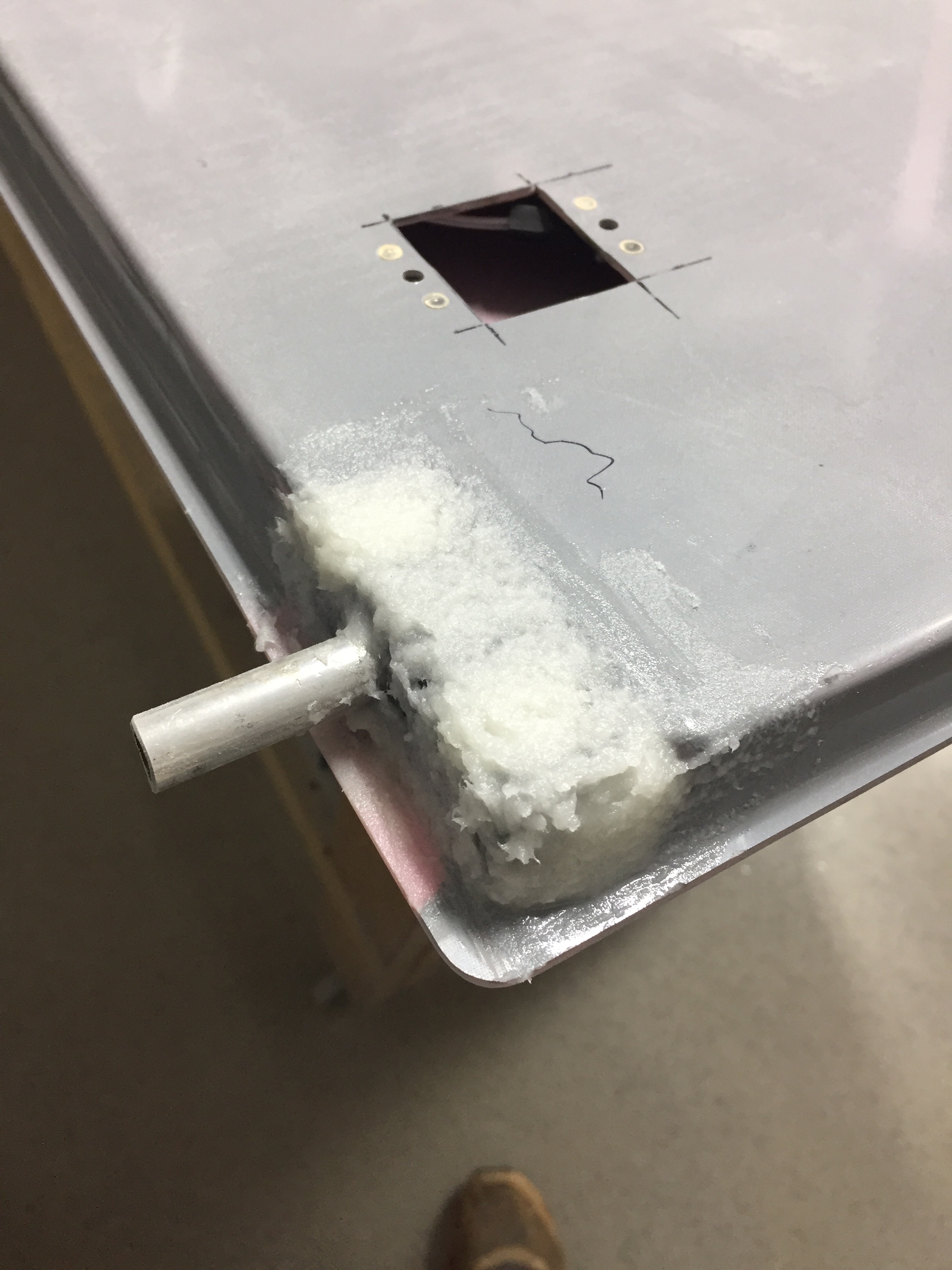
I want a really finished looking product for the doors which requires covering / filling in a few key spots such as the pin guides, hinges, and install holes for the gear rack and center cam.  Some have laid fiberglass over these areas, others have left them open, and a few folks are using basswood to create cover plates.  Since I’m better at the wood and had some on the shelf, that’s what I chose to do.  The pin guides I just roughed up and applied flox directly on them, roughing the shape in to match the door lines.  I used some scrap pin material to keep the hole clean.
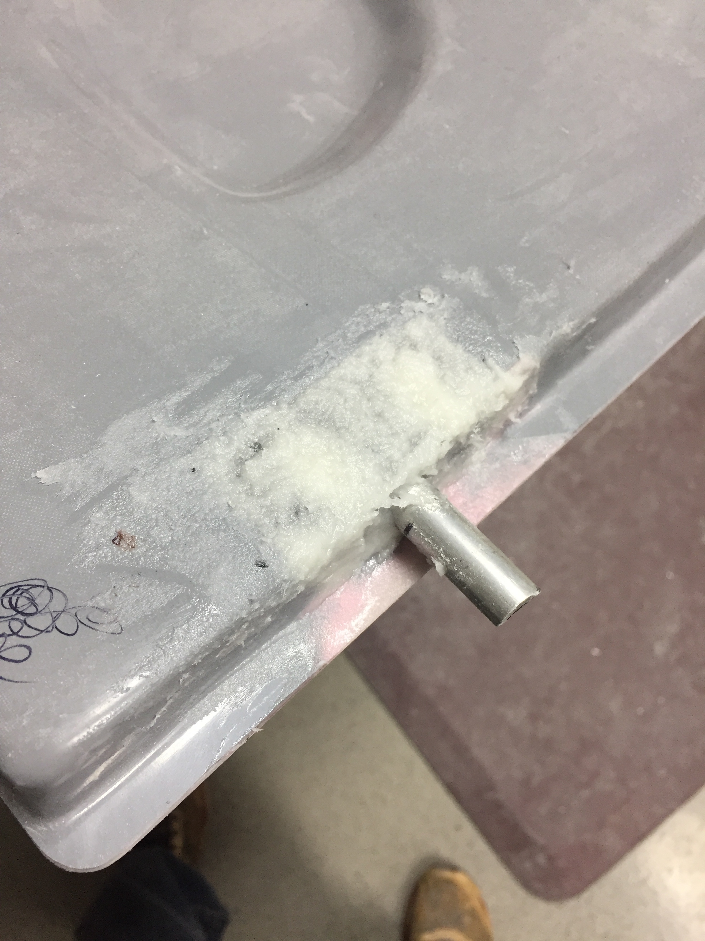
 

I used the basswood to fill in a hole used to install the center latch and create covers for the hinges.  It was pretty easy to trim and shape the wood for the plates needed and after I coated all sides with epoxy to harden the wood, I epoxied the plates in place.  I then went back with Superfil and did the final contouring and shaping to match all of the door’s surface.  I’m really happy with how it came out and while it was a bit of extra work, I think it’s worth it in the end to not look at exposed hardware.  I’ll be covering the hinges on the cabin top down the road as well.  Finally, I took some time to fill in little surface blemishes and final shapped the interior edge of the window frame.
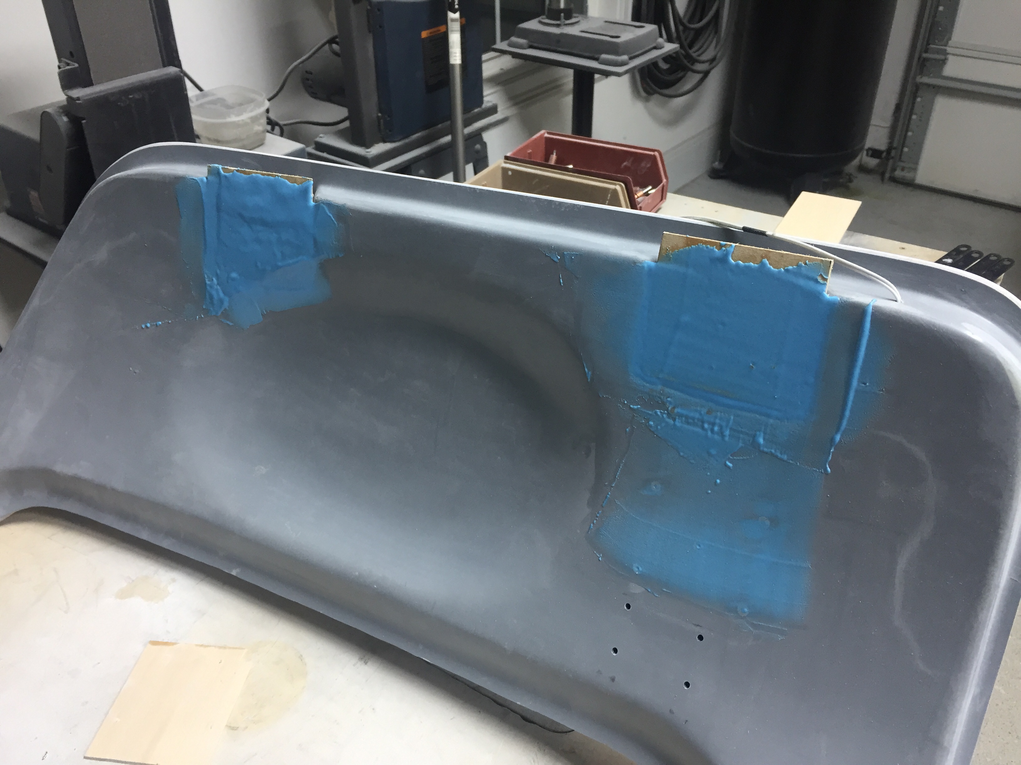
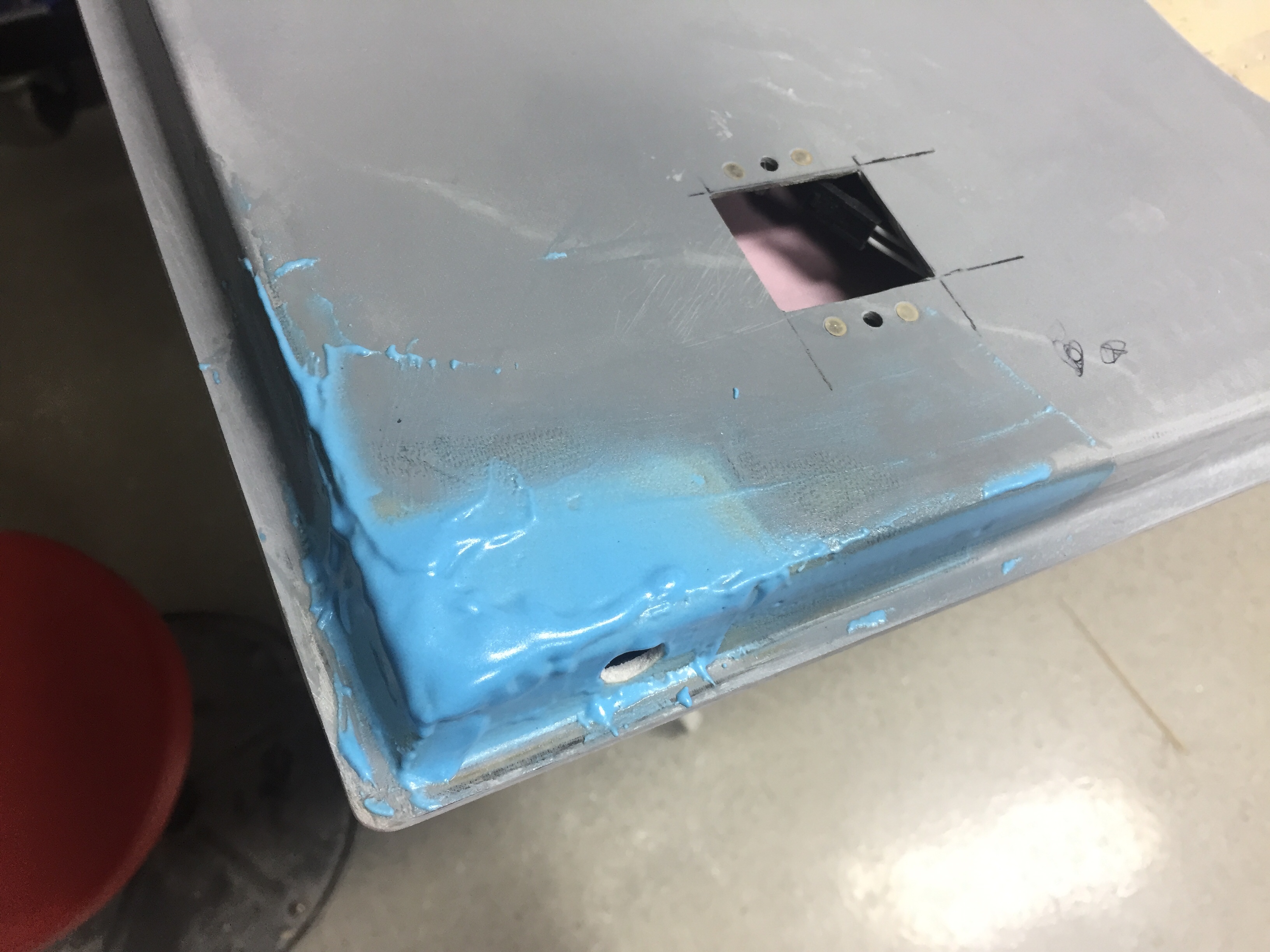
 

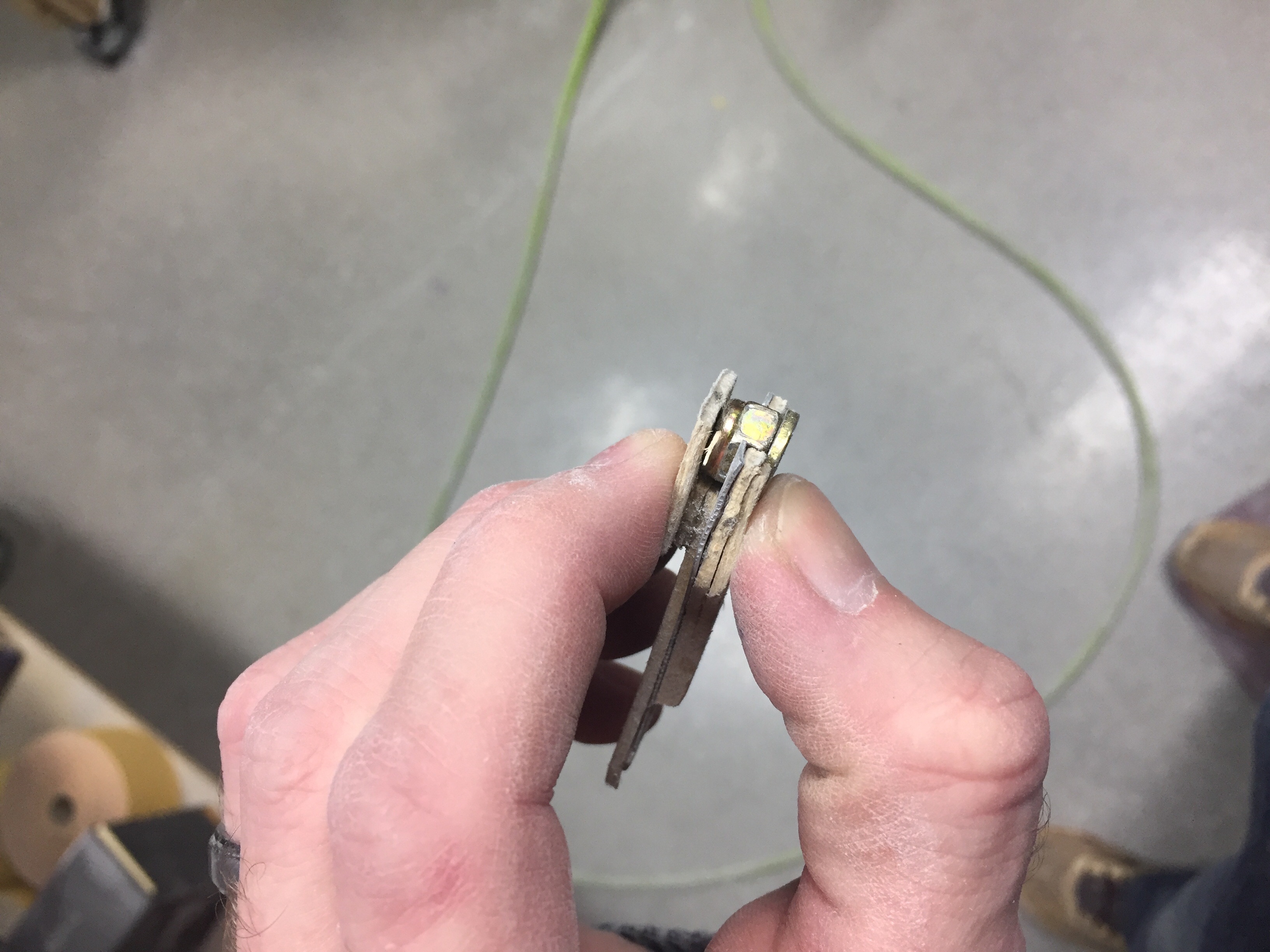
After all the sanding was done and I was happy with the doors, I wanted to re-mount them for the final time.  Here is where I realized I screwed up.  The hinges are mounted to the cabin top with the hardware essentially epoxied in (see prior post) so I had to slip the door onto the hinges and install the hardware behind the new cover plate I had spent all that time creating.  Bad idea.  It’s impossible to get the washer and nut on each screw on the door side of the hinge.  My fingers are fat and not triple jointed so I spent an hour raising my blood pressure far beyond healthy limits struggling with it.  I decided to walk away, burn the project to the ground, and start over.  Okay, really, I just took the rest of the night off.  The next evening with a calmer approach, I fabed up a handy little tool to hold the washer and nut in the cavity while I installed the screw.  I used some basswood and some aluminum to create a captive wrench so to speak that worked beautifully.  Had both doors installed in about 20 minutes.  Wish I had put the hinges on the door then bolted them onto the fuselage, but oh well.  I installed the last plates to close out the hinge area and applied filler to smooth is all over.  This completely closes out the hinge cavity on the door not only making it look better but allowing the door seal to work properly.
 

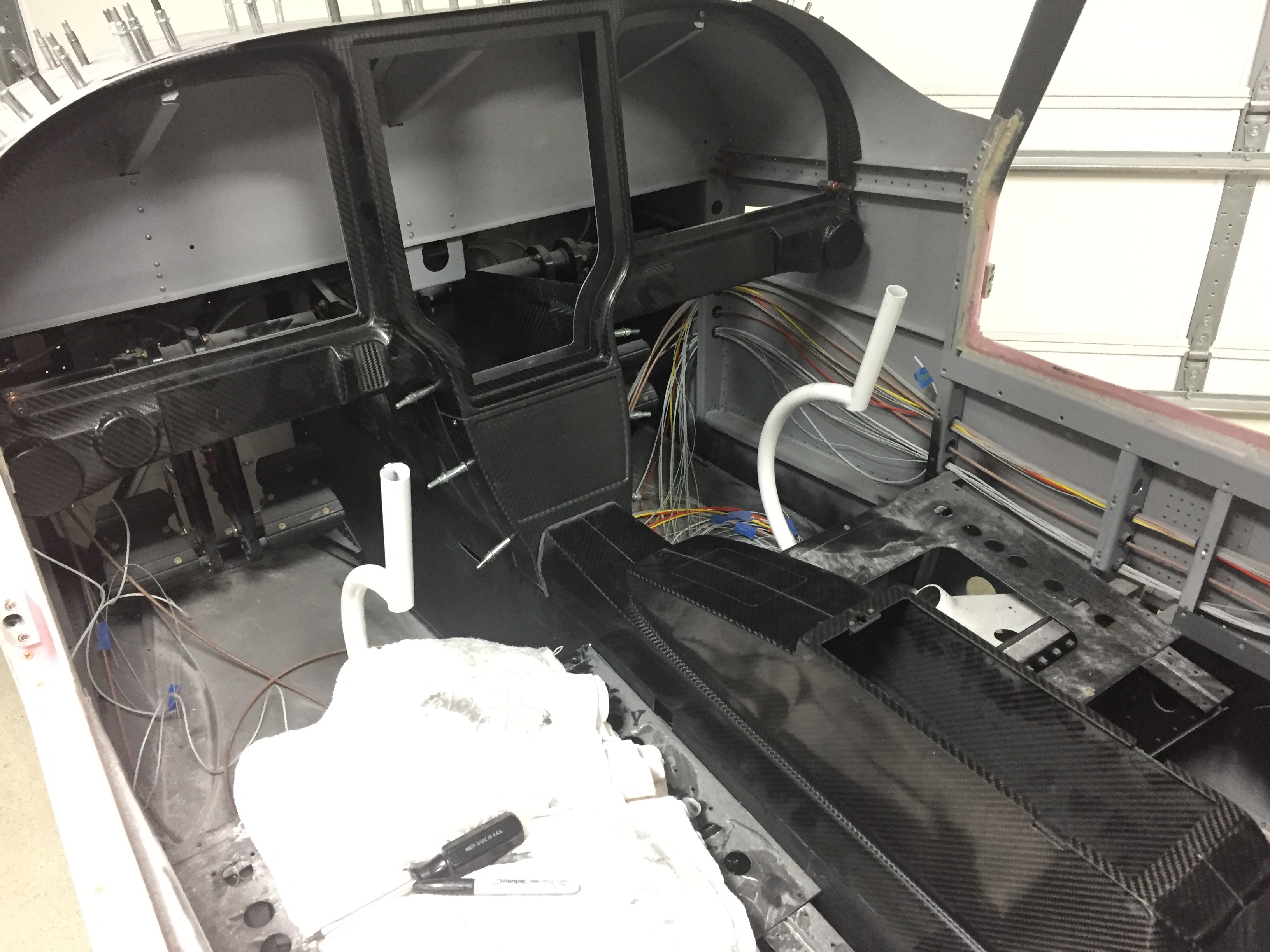
Meanwhile, I set about working on the instrument panel and center console.  The big Aerosport order had arrived a few weeks prior and I was eager to play with all of the cool stuff.  I started with the instrument panel and got the backing plate and the panel itself fitted in their place.  The side skirts on the tunnel attach to the lower instrument panel with the center console mating up to it.  This stuff is top notch quality and is going to be really awesome filled with fancy avionics!  I took my time to fit it all and used nutplates to ease future maintenance and removal.  I chose to countersink the carbon which left it a little thin and brittle, so I coated each screw hole with light epoxy to help strengthen the area.  I also cut out the main areas which will have the metal inserts leaving a 1” flange to be trimmed to final size later.  The center console was positioned and I used a strap duplicator to drill the holes matching the tunnel.
 

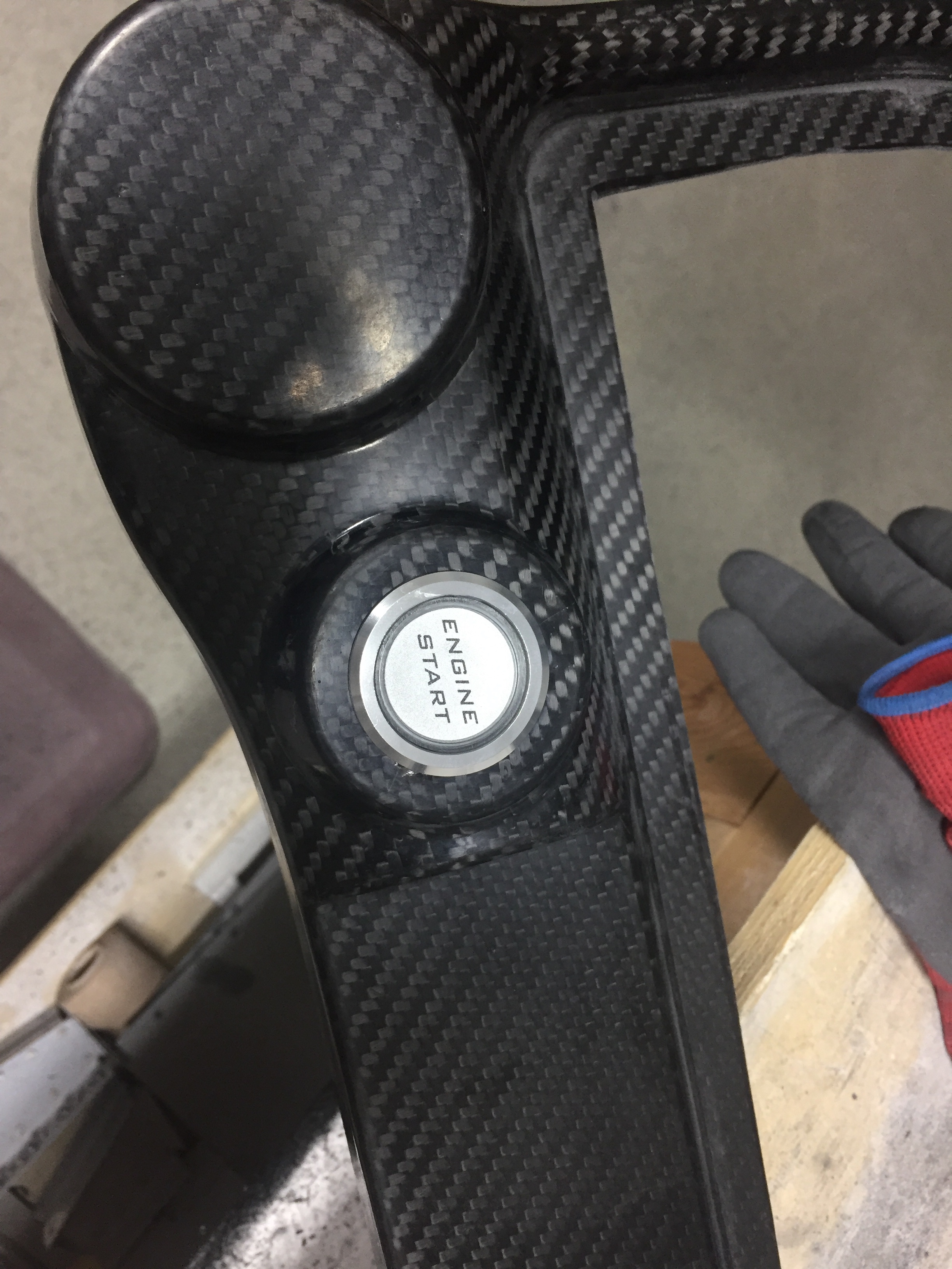
Since my plans include using the ACM from AFS, I want to use a fancy push to start button but couldn’t really find one that I liked.  The Honda S2000 button others have used are hard to find these days so after a few returned orders, a deep Google search turned up exactly what I was looking for.  It’s a simple Apem NO switch that has a LED light actuator.  It’s also the right size to be proportional to the panel location.  I couldn’t help but to drill the hole and mount it up to see how it looked.
 

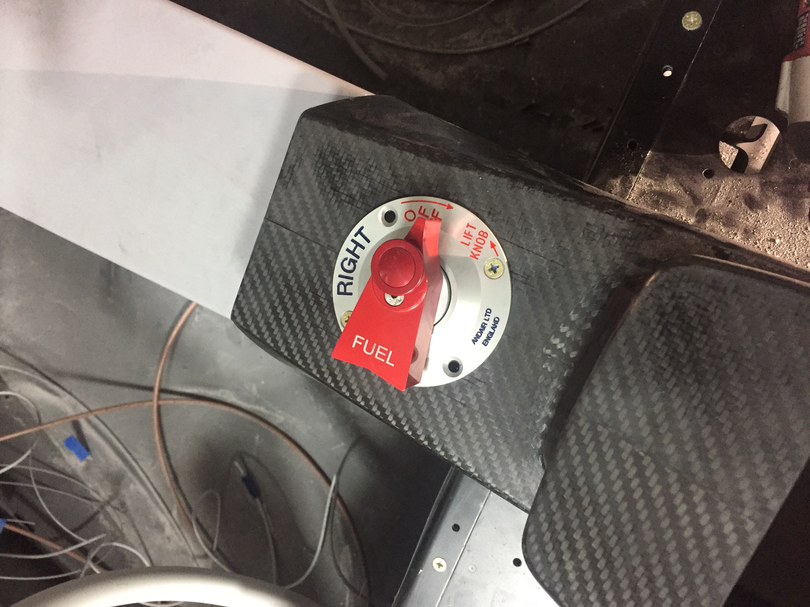
The Andair fuel valve is mounted through the tunnel on the center console as well, so I set about locating the screw holes.  I mocked up the valve itself on the stock mount and will need to create a larger mounting plate for the valve housing down the road.  It allowed me to trim the handle extension and locate the plate on top of the console.  Again, had to mock it up and do some airplane noises while turning the valve.  The noises worked perfectly; so did the valve.
 

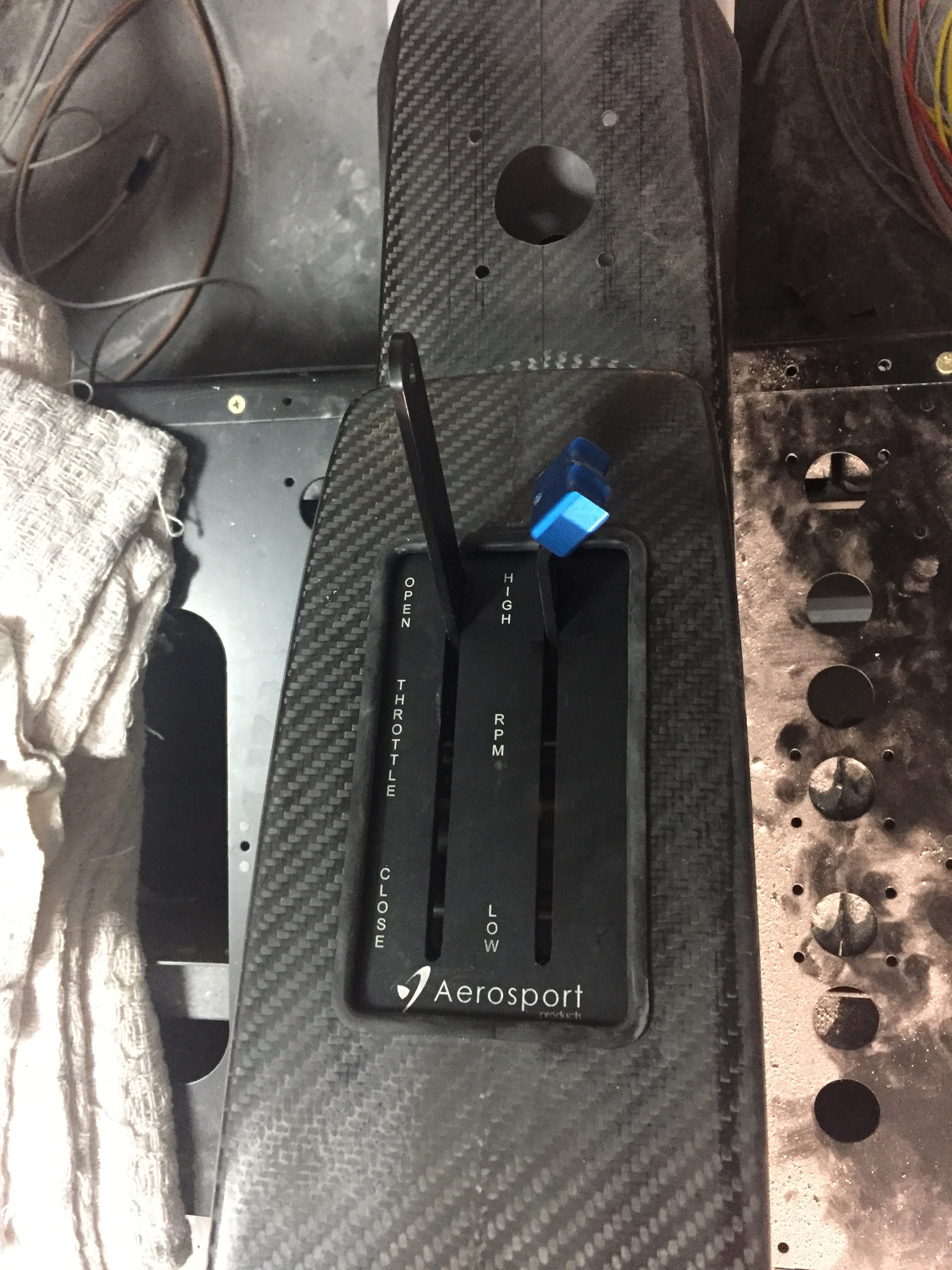
Finally, I cut the throttle quadrant area out and worked on installing the quadrant onto the tunnel cover.  Thanks to Ed and Aerosport’s awesome YouTube video, it was pretty painless and I wound up with a very nice fit with the throttles fitting flush with the console when everything is installed.  I cut a large slit on the throttle friction lock area that allows easy removal of the console.  I’ll create a trim plate to cover up the slit for a finished look.  With the main carbon work done, it was time to drop off the instrument panel parts and center console to a paint shop for a clear coat.  I want to leave the carbon look exposed but wasn’t happy with the finish right out of the mold.  I had originally asked Aerosport to clear the items but they quoted over $1500 just for the clear coat.  I almost choked.  I love them to death and they’ve done a lot to help, but I couldn’t swallow that pill.  A few calls around the area and a local custom motorcycle paint shop could perform the work in four days for $250.  We’ll see how they turn out next.
Fun with electrons

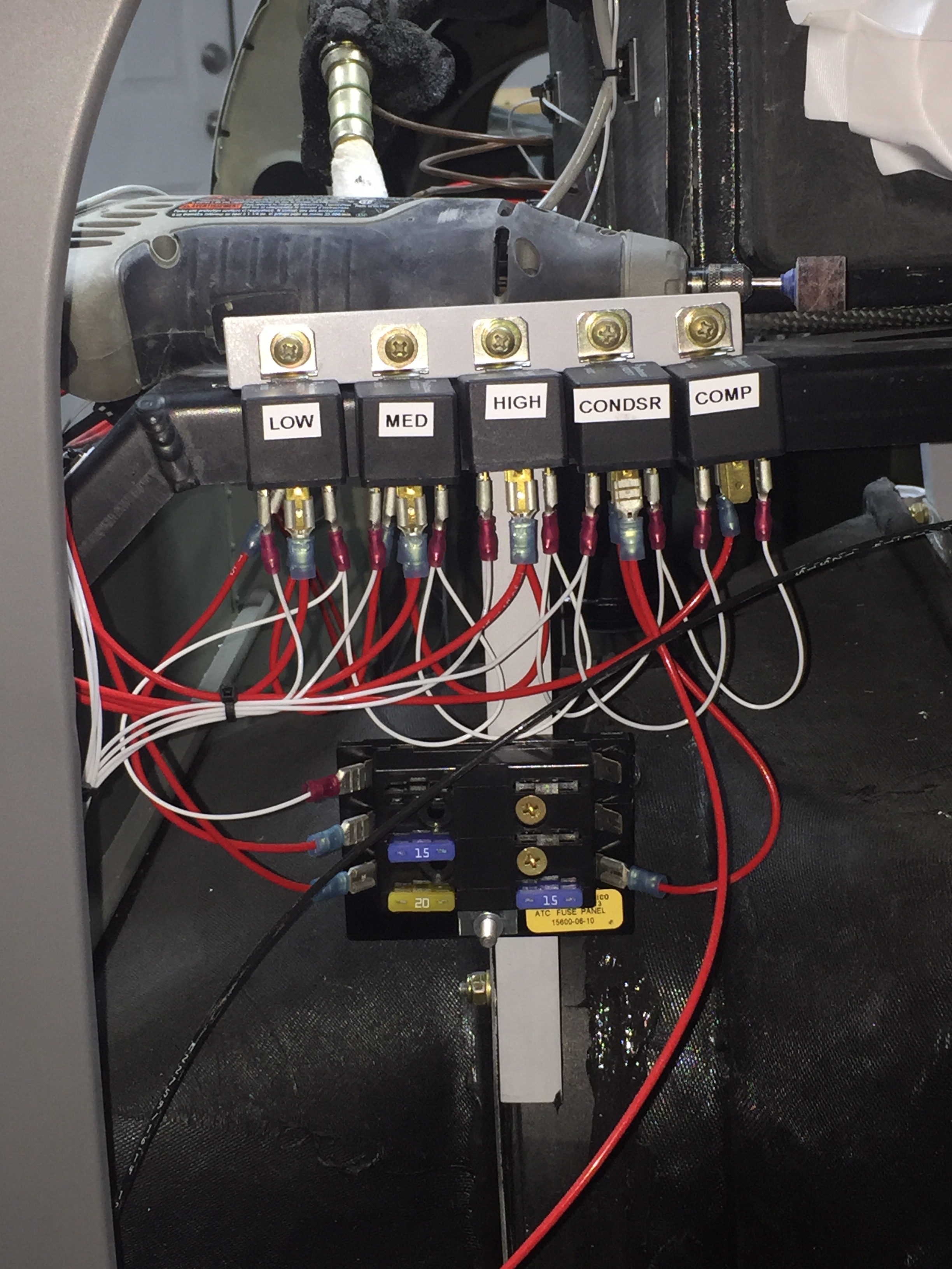
While waiting on the finish kit, I worked on a few electrical to do’s on the build. The AC system is installed, but all the wiring still needed to be hooked up. The system’s controller uses relays and I decided to move the location of the fuse panel to the bulkhead for easy maintenance. The relays were labeled and mounted to angle aluminum on the equipment tray. A lot of wire connectors later, the relays are all hooked up and the wires up front are pulled. I also wired the condenser fan with a disconnect for future servicing. The only wire not run is for the compressor, as I may go with an electric compressor depending on a few things down the road.

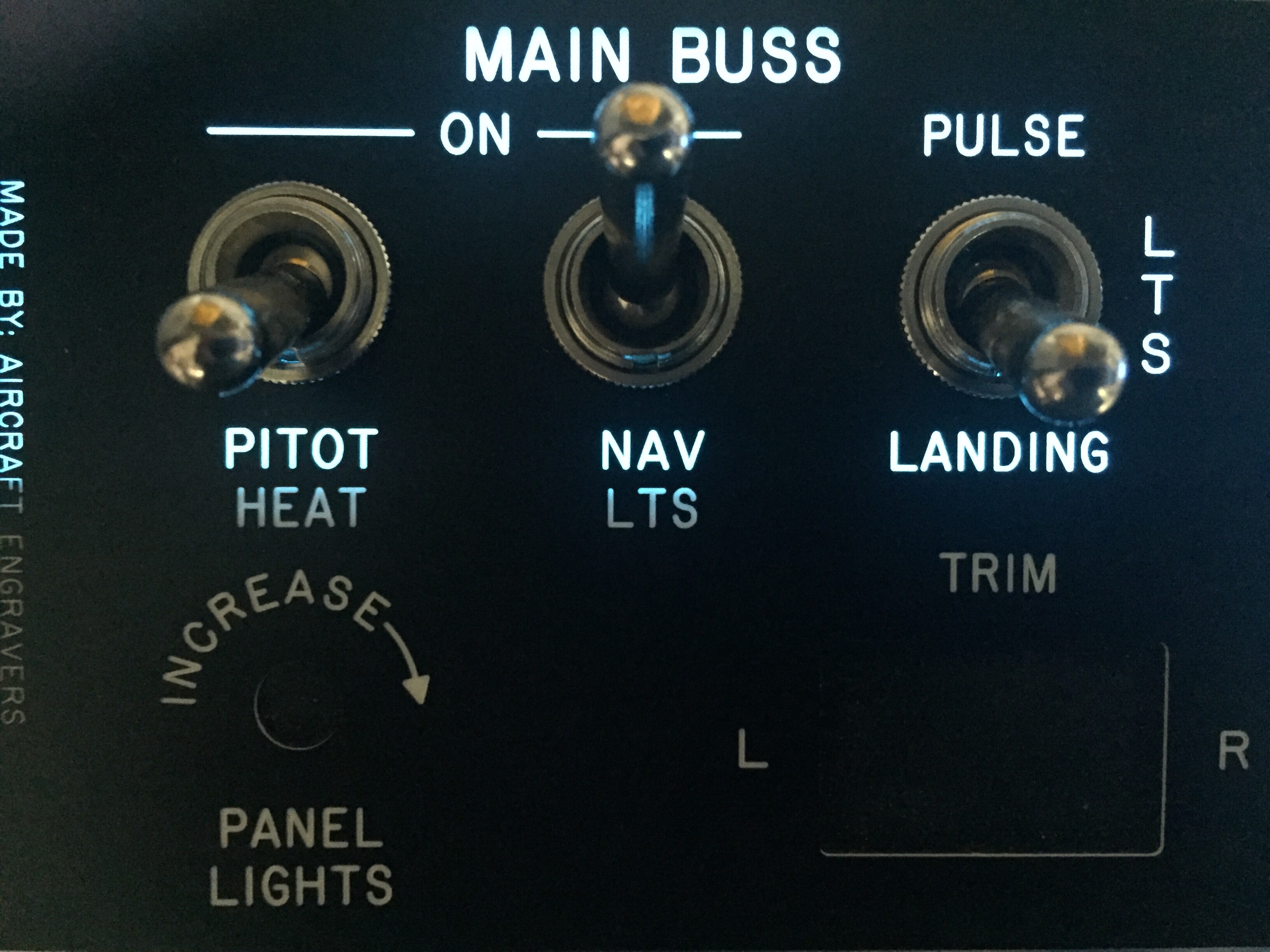
I also received a sample of the electroluminescent panel to experiment with backlighting my instrument panel. Aircraft Engravers sent me a sample panel on acrylic that I put on the EL panel and am really excited about the results. The EL panel put off a nice amount of light and dimmed well. The sample panel looked great and is easy to produce as well. My plan is to have Aircraft Engravers produce the panel overlays in acrylic which I will mount on top of the metal panel inserts holding the avionics. The EL panel will be sandwiched in between. In theory, it will be a nice clean look to the panel and have a high end backlight to boot. I took the EL panel with me in the Diamond on a quick flight to see if there was any noise from the transformer and didn’t notice any issues. Not a overly scientific test, but enough to keep me motivated to make this work.

I only had a 1″ strip, so you can see the difference where the panel is not backlit. The EL panel is also white when off, not the typical pinkish so the panel during the day appears to have white lettering as typical. More to come on this!

Kool like Krantz

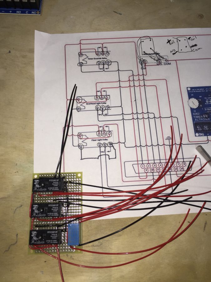
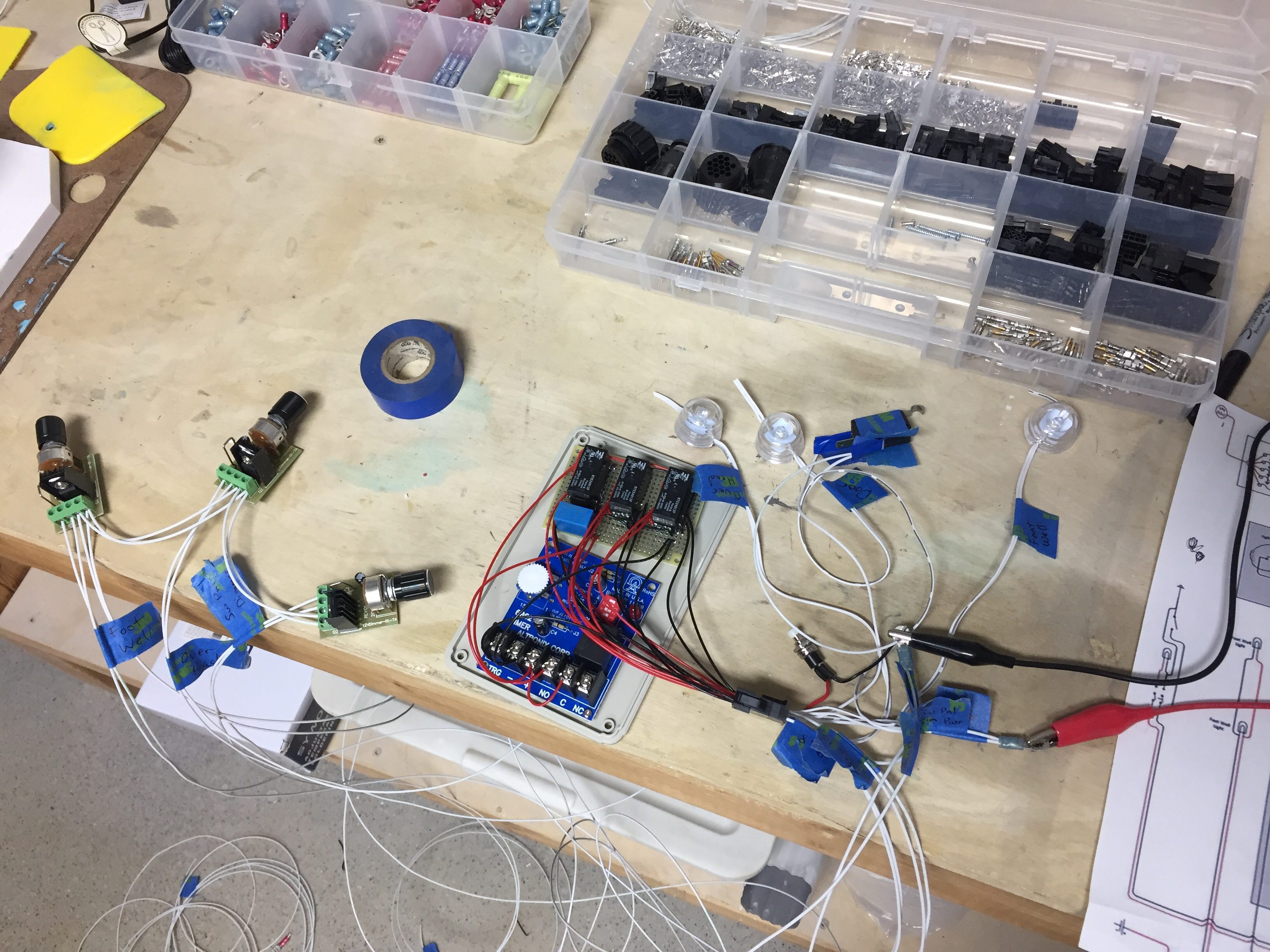
In between working on the overhead console, I decided to tackle a fun little project dreamed up by Ed Krantz (Good Plane Living) to control the interior lighting. He came up with a fancy little box full of relays and a timer to essentially make the lights behave as a modern car. While this doesn’t seem fancy, most little airplanes have one dome light from the 1960’s, so this is all pretty high tech. The best part is he designed it to work as a DIY project and kept it simple and functional. The best, best part though is he shared it online for others to benefit from, so thank you!

Without diving into the actual wiring schematic, the little box receives a signal from a micro switch that a door has opened. This in turn causes the three overhead LED lights to illuminate, the footwell lights, and under panel lights all to come on to full brightness, even if they were on using the dimmer. The timer is used to keep them on for a set amount of time then they all turn off. Once the door is shut, the whole system resets and the lights return to their prior state, either off or according to their dimmer.

I’ll have two additional LED lights, one on each door, that shine down on the wing when the doors are open. Ed had put each task light on the control as well, but I chose not to since I think the three overhead will provide plenty of light.

It also has a manual reset switch to allow a door to be open but reset the lights to off or dimmed in case you want to have a door open while taxing or any other reason. There will also be a master switch near the rear baggage door to control overall power. This is because even after the lights are reset, the timer does draw a small amount of power and in theory could drain a battery if left for many days, for example during extended maintenance.

After a few hours of laying out the components and soldering it all up, I hooked up a few cheap-o LED lights to test it all out. Just as Ed did, I forgot one ground wire but that was soon fixed and everything worked just as designed. It was a really fun project and will make night flying / loading a non-issue.

So on the overhead control panel, I will have all lighting switches (Nav, Strobes, Taxi, Land, Interior Reset) along with the dimmers for the panel, instruments, and interior lights.

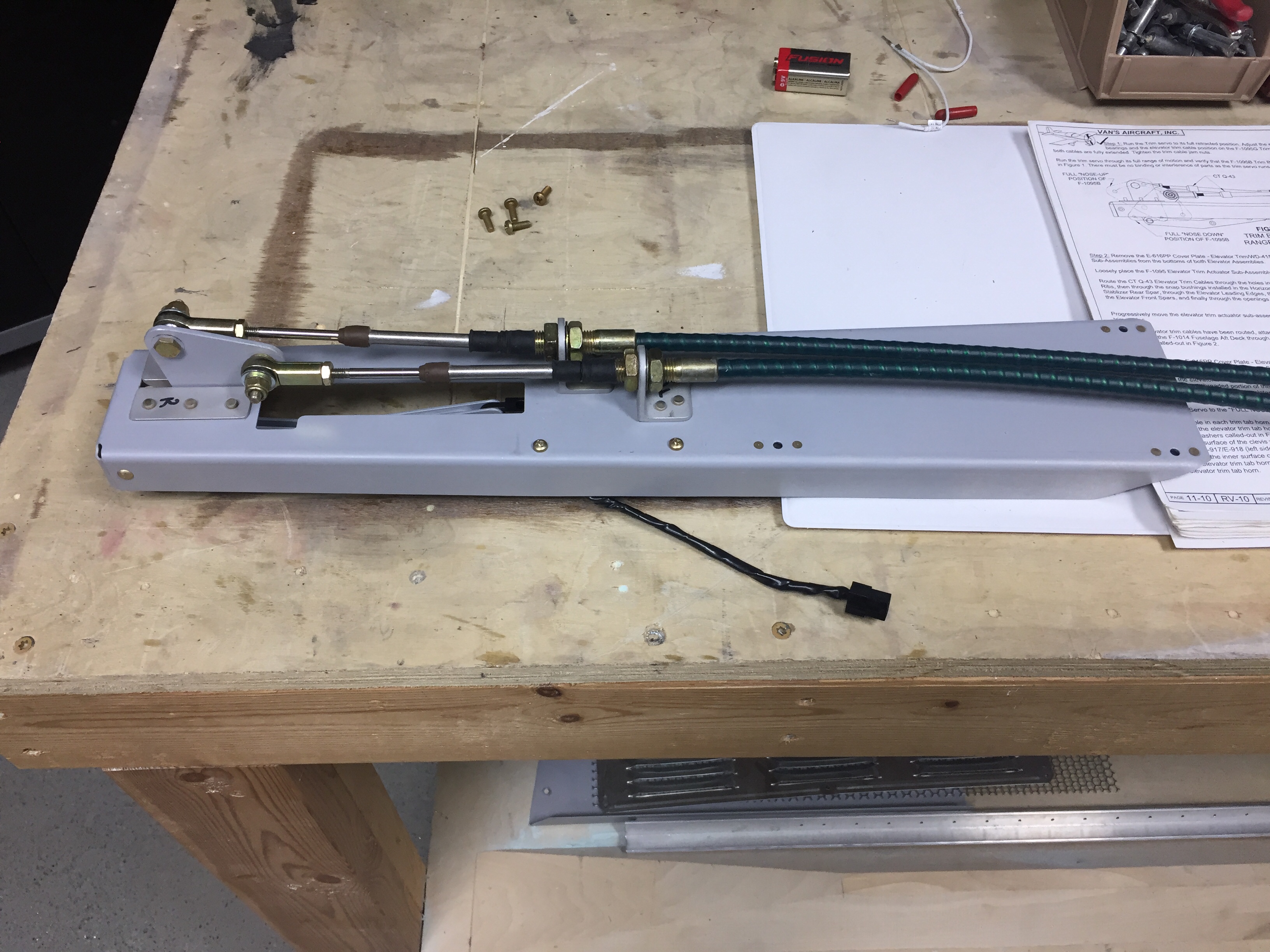
I also fabed up and installed the pitch trim servo mount. It was a pretty quick job and the wiring for the servo was already pulled during an earlier build session. I’m trying to get as much wiring roughed in now before much more structure goes in place.

Controlling the overhead

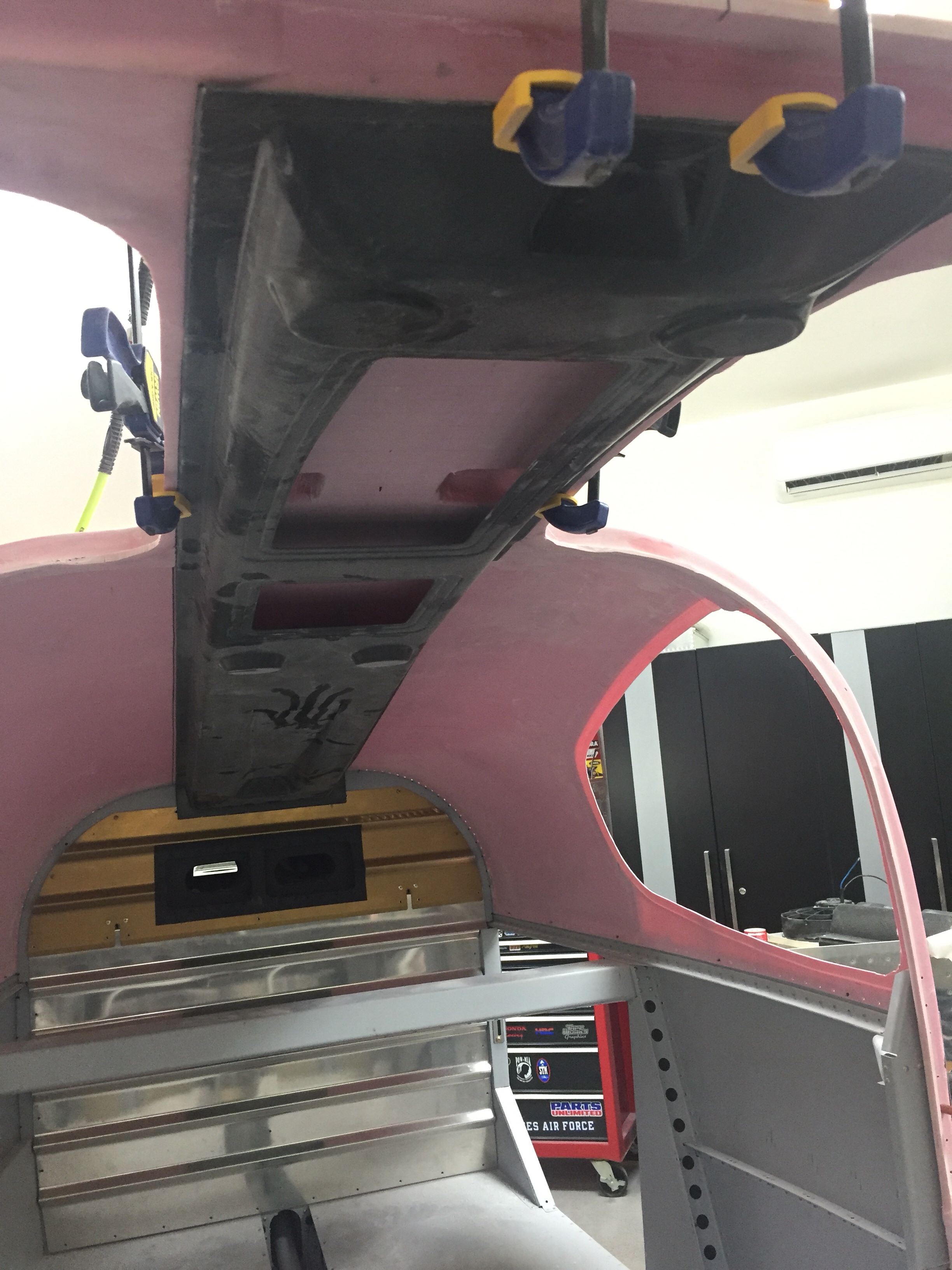
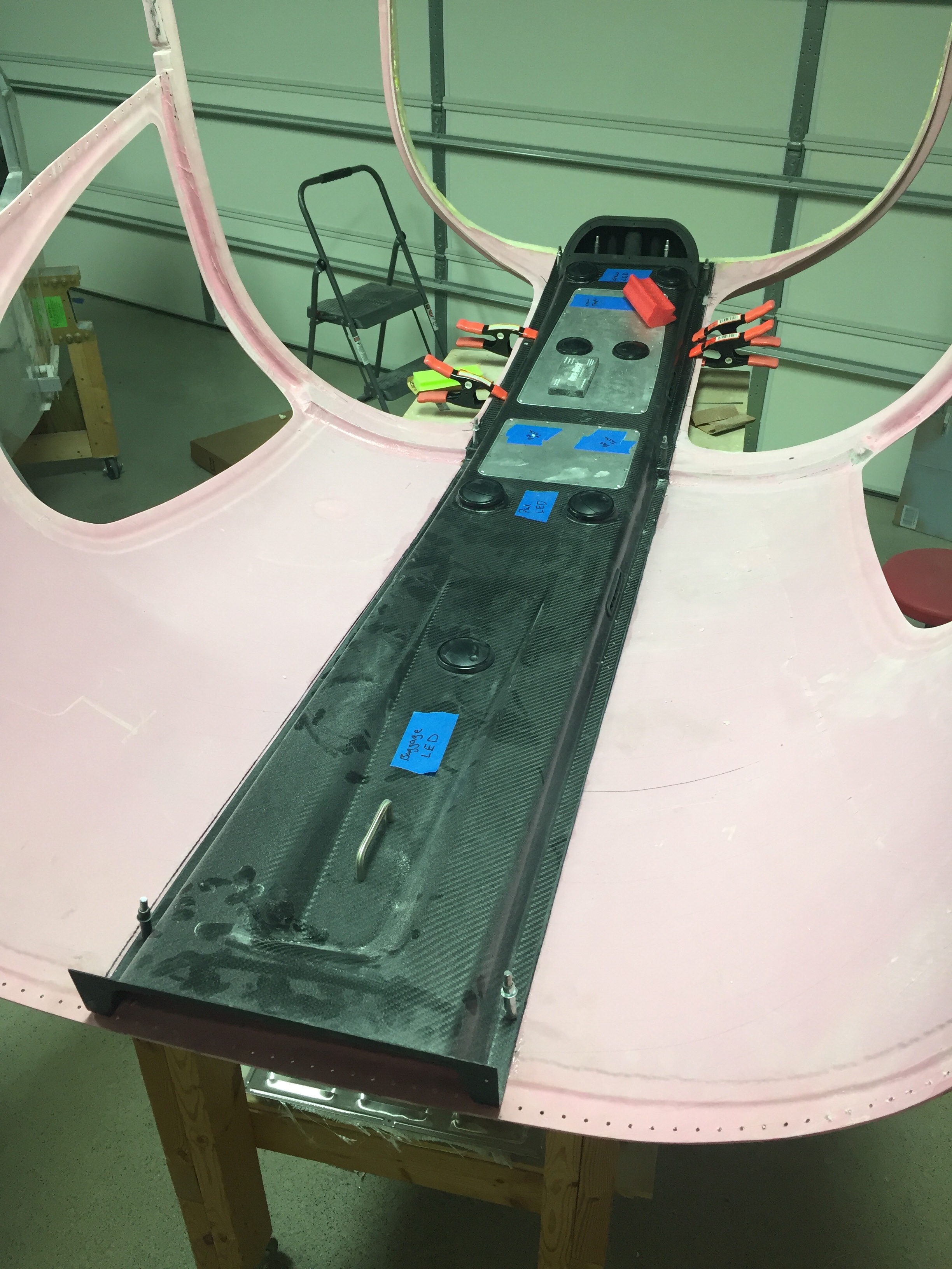
One huge task to complete before the cabin top can go on for good is the overhead console. This piece of art comes from Aerosport and allows the vents for the air conditioning and the lights to be mounted on the cabin top. I also have one of the first production examples of the overhead switch panel that Ed Krantz molded up.

The first step is a rough fit and trim to get an idea where the interference points are. The mold they use is pretty accurate but has a few spots that needs adjustments. I didn’t have to cut the joggle around the step in the cabin top, however, there were a few spots up near the windshield that were too bulbous and had to be ground down. Overall, the initial trim and sanding was a pretty quick and painless job.

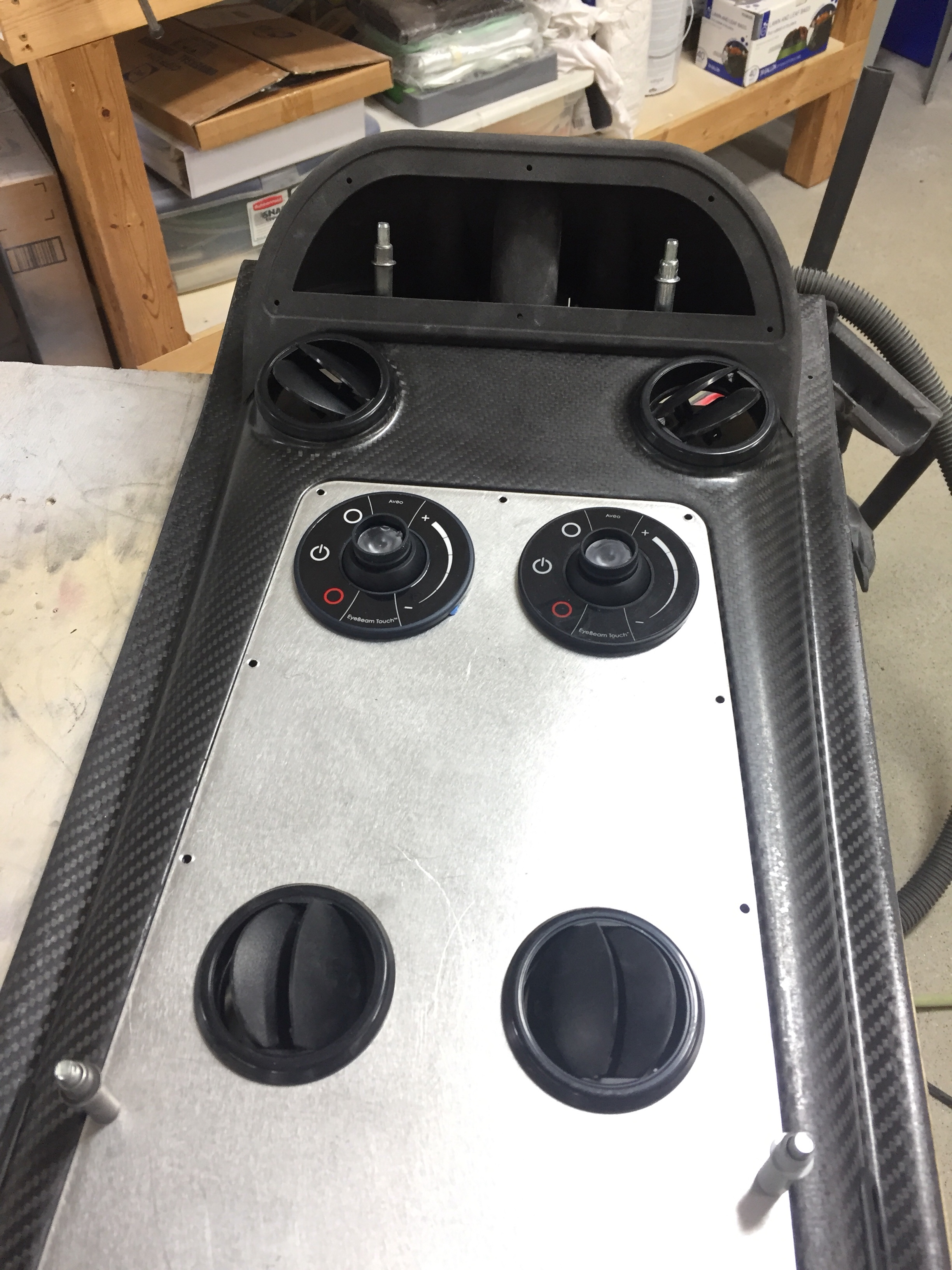
The overhead has two large aluminum panels that can be used for lights, vents, etc. but need nutplates installed to secure them. Pretty quick job to set it all up including countersinking the panels for flush screws that came out very nicely. I also decided where to mount the four curtain vents that I got from South Florida Sport Aviation. They are using the Airflow Performance set up on their own interior and despite my best efforts, I couldn’t find any vents like these online. I like these because it allows good airflow along the windows as well as alternate airflow if one or more of the vents are closed, keeping good flow through the cabin and over the evaporator which is key to efficient performance of the air conditioner.

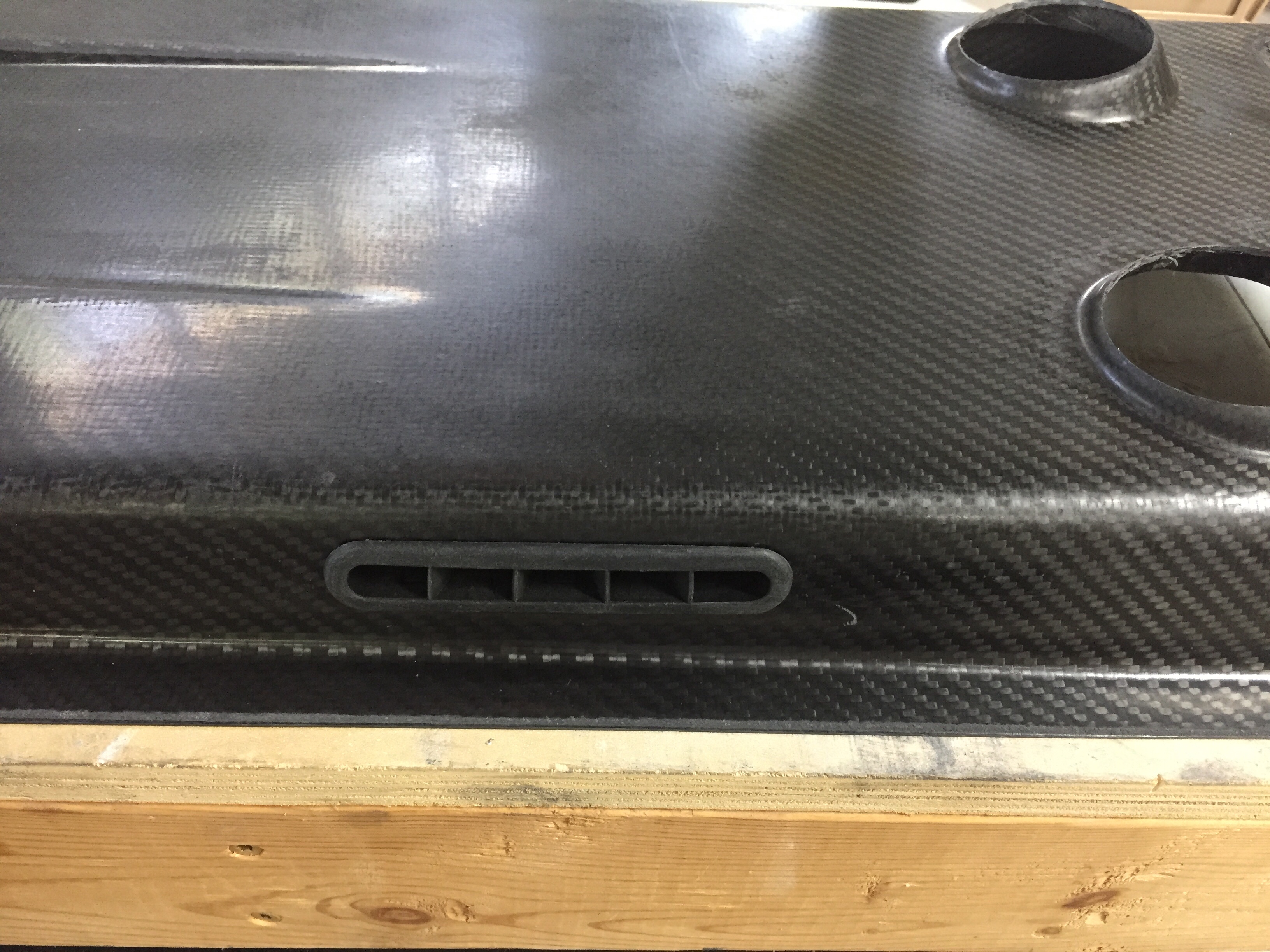
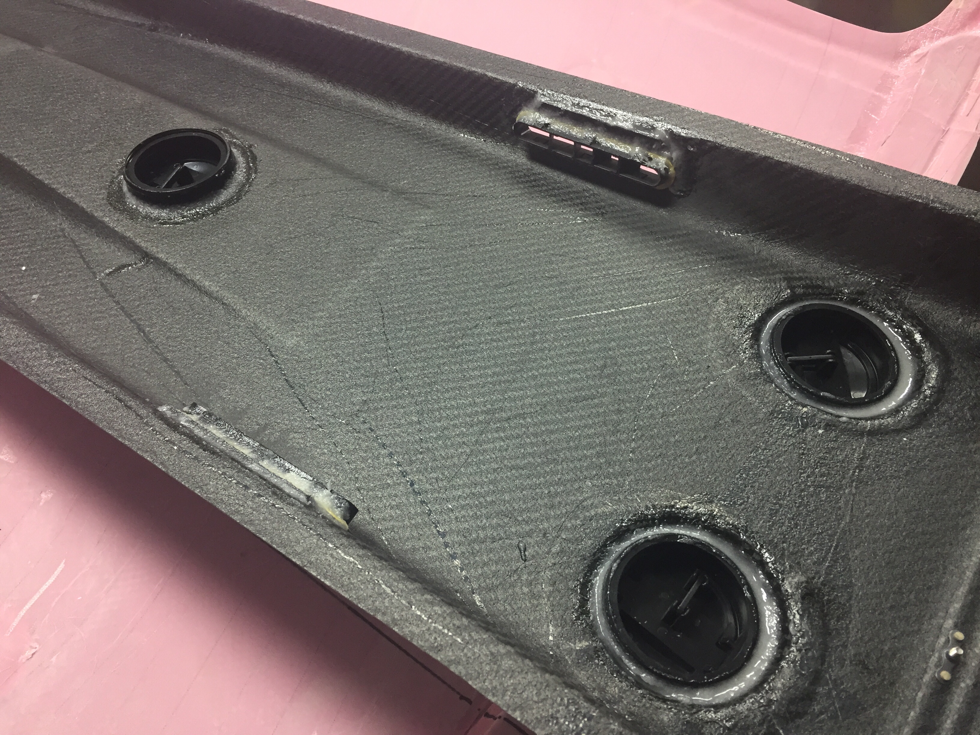
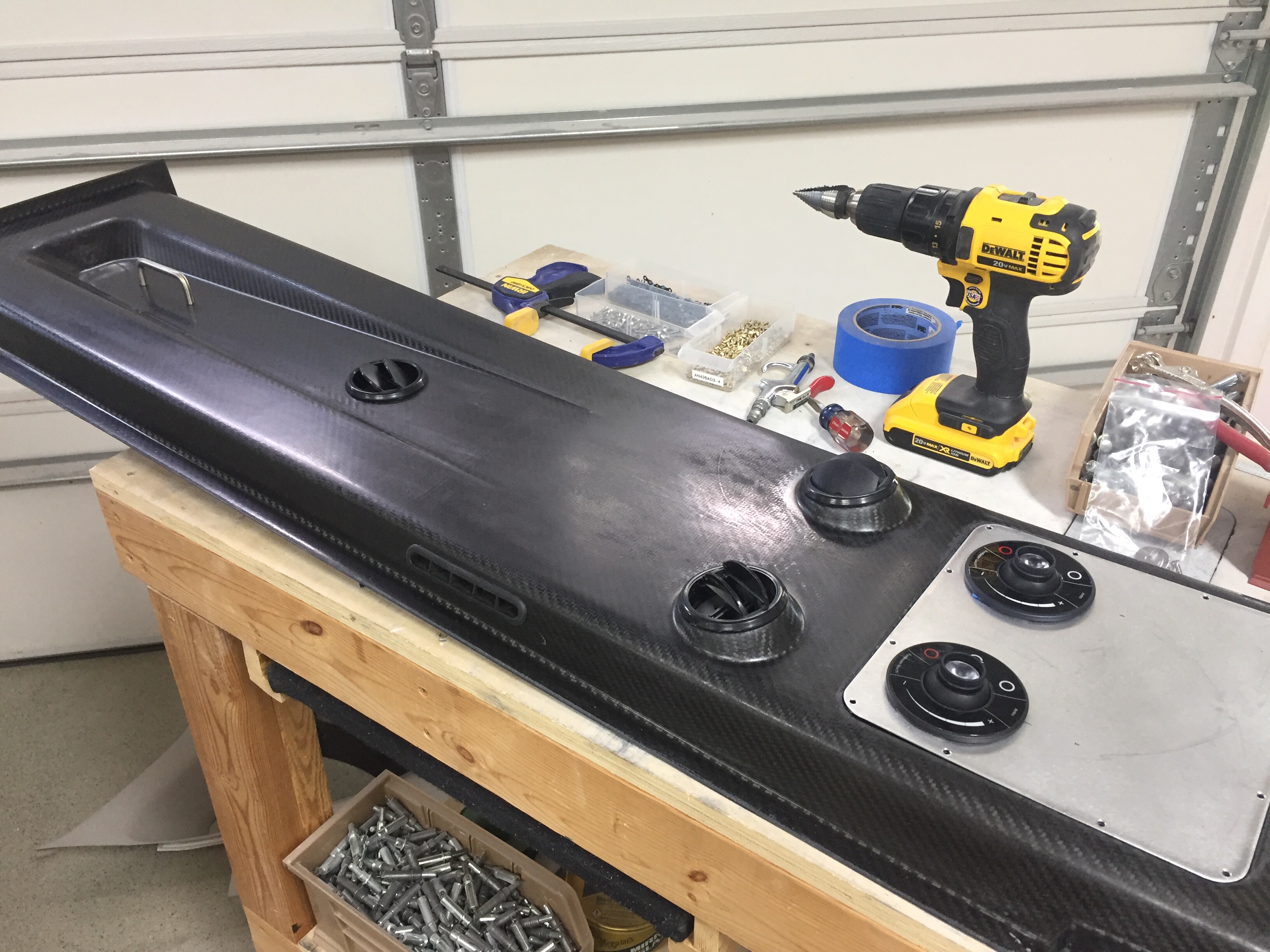
I also used the four molded spots to mount air vents in as you can see the cutouts above. Most have used either the eyeball vents or a universal car vent. Based on feedback from others and the astronomical price of eyeball vents, I decided Summit Racing vents would work better. They were $20 each instead of $120 each and I think will allow a lot more air to flow while being easier to use. I simply used epoxy/flox to secures them to the overhead taking care to not have any leak on the vents themselves. I also put two vents in the metal panel so that the pilot and copilot each have two vents, hopefully keeping me cool up front with all the glass. The panels will also hold an Aveo Eyebeam Touch task light for each seat.

Lastly, I installed the coat hanger in the rear which will probably rarely be used, but hey, it’s part of the kit and looks good. I can also use it to call this a business aircraft!

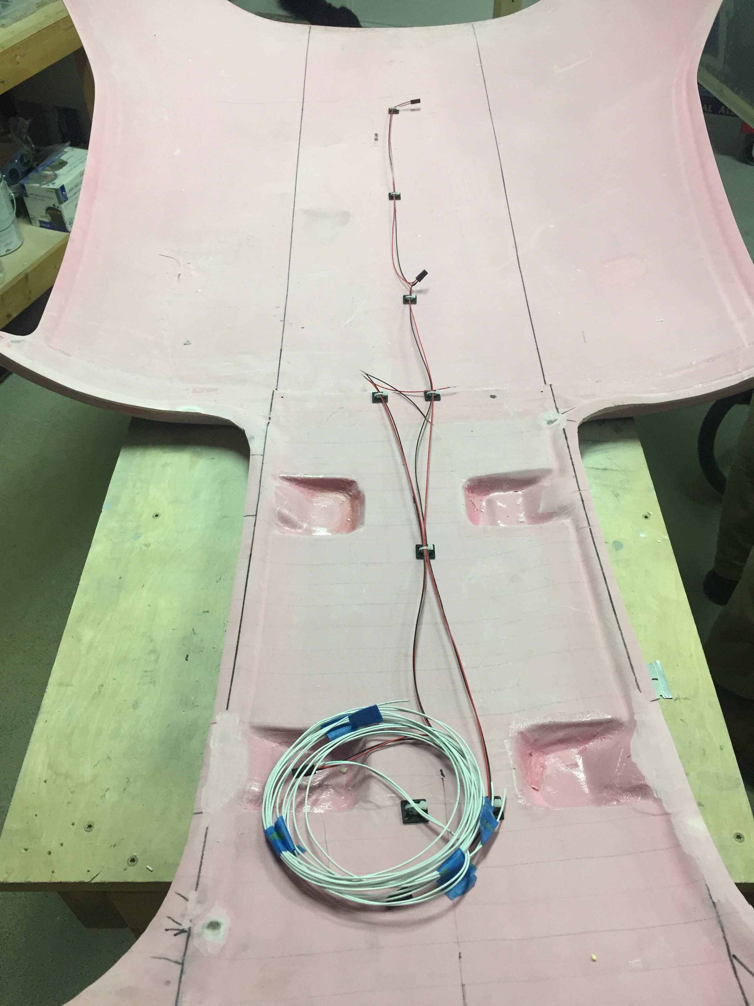
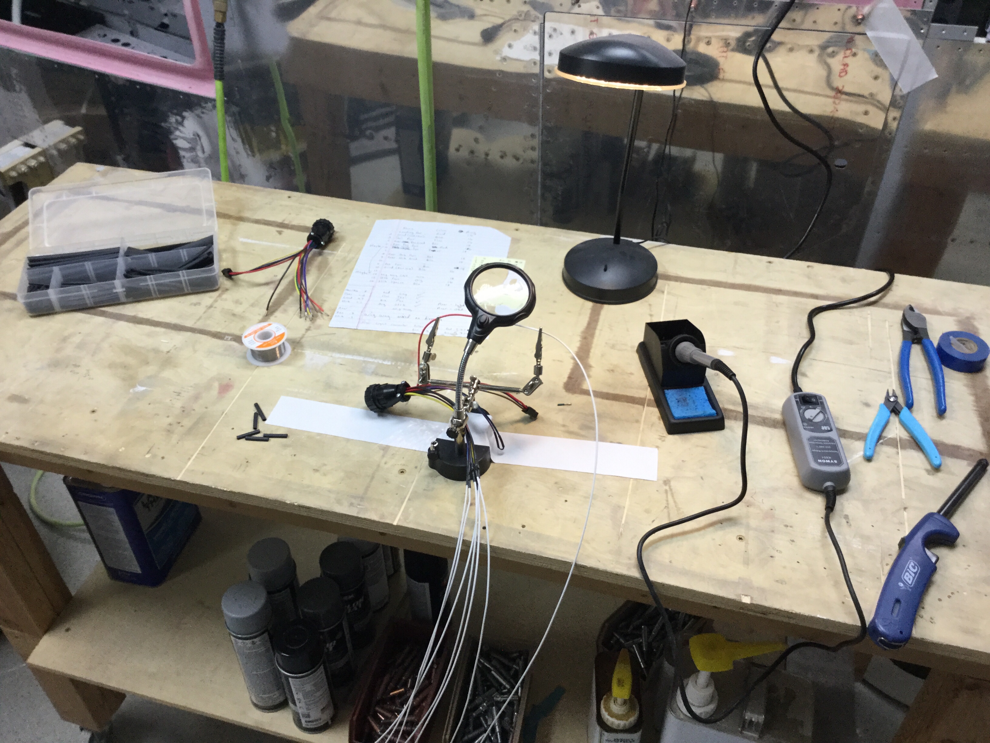
I will be running the wires for the switch panel and the task lights up through the center post so wanted to get the wiring that will be in the overhead completed. I went ahead and made up the wiring harness for the four task lights as well as the three overhead dome lights that will be used for general cabin lighting. The pictures show bare contacts, but after another order from Mouser came in, I installed the Molex connectors so that everything is line replaceable without cutting wires. I also cut the three holes in the overhead for the lights.

Finally, after one complete evening off of the cabin top to clear my head and make sure I’m not forgetting anything, it was time to epoxy it on for good. I mixed up a healthy amount of epoxy/flox and fortunately had a friend to split the task of spreading the mixture and setting it in place. With a couple of clamps and clecos, it fit well and made a secure bond to the cabin top.

Next up will be shaping and filling the assembly to get it all prepped for paint and final instal.

Wired for moving day

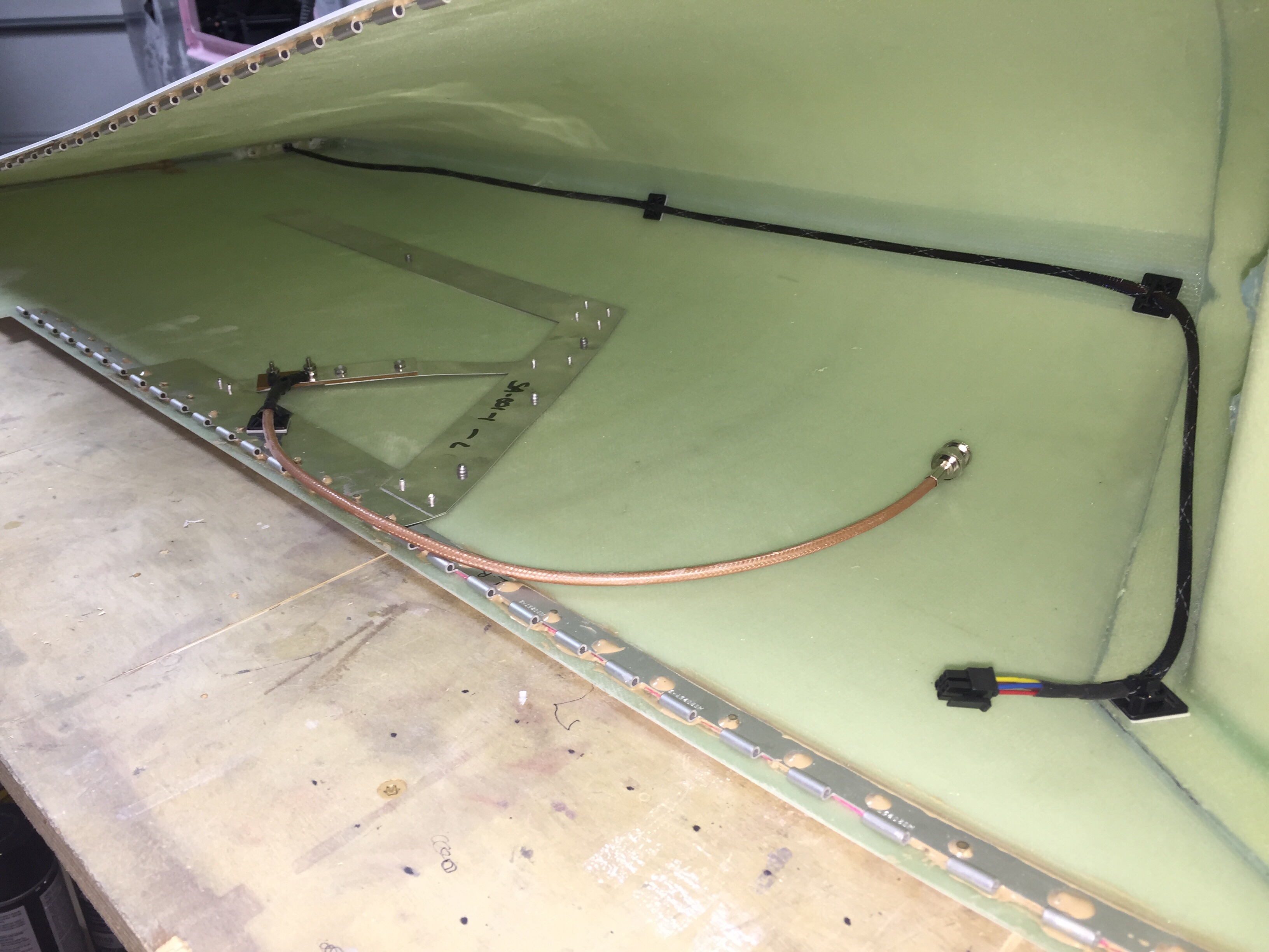
With the tips fitted to the wings, it’s time to run some wiring and finish up the wings. I integrated the Archer nav antenna into the tip mounting hinge which thus links the antenna to the wing for a proper ground plane, per the plans. I used a few pop rivets through the bottom of the tip to secure the antenna in place. I wanted to make the tips easy to remove, so I used bulkhead BNC fittings for the coax on both end of the wings.

I also ran the wires from the trailing edge position / strobe light up towards the main lighting modules and installed a micro fit connector so that the lighting module can be removed for future maintenance / replacement should the need arise. Again, all of the wiring has been documented in Visio including pin outs on each connector so I’ll be able to reference it long after I’ve forgotten how or why I did it this way!

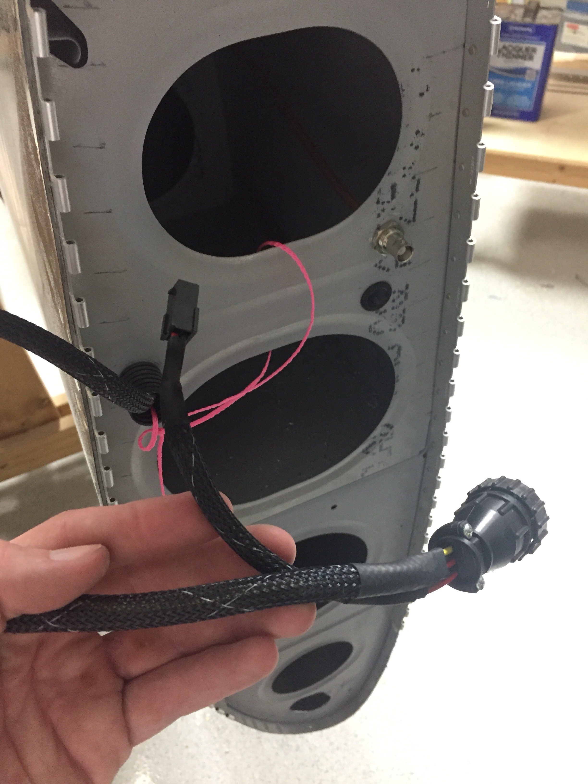
I used CPCs for the main wiring runs and am very pleased with the setup. Some folks avoid connectors like the plague, but I don’t see them as failure points if they are done right and properly tested / treated. I checked continuity of each wire after running them all so I know everything is ready for plug and play. The wing root connectors include those for the pitot heat and AP servo on their respective wings. The aileron trim servo is on it’s own micro fit connector due to the small wire size. I’ve gotten really proficient at the micro Molex connectors and really like them.

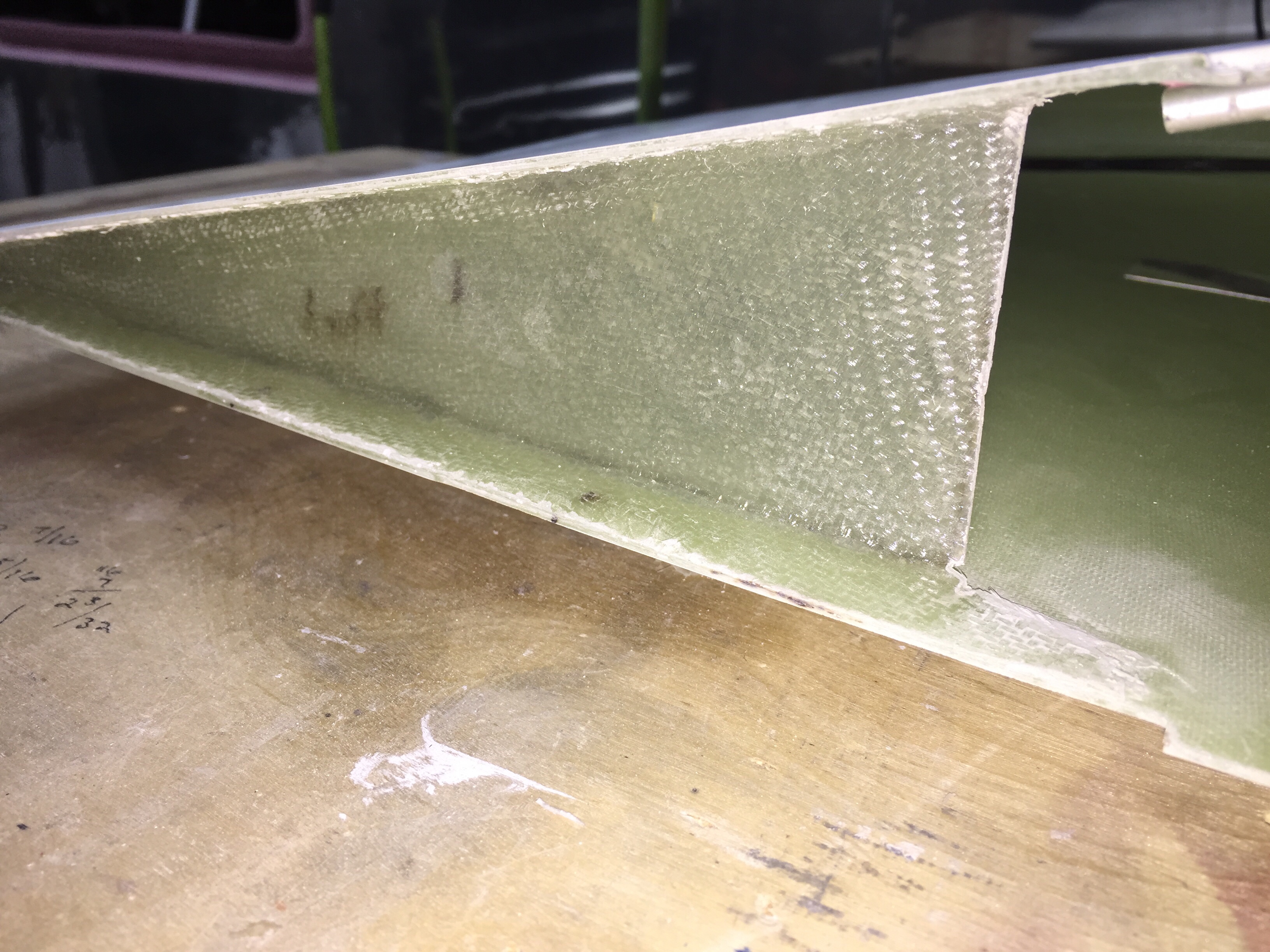
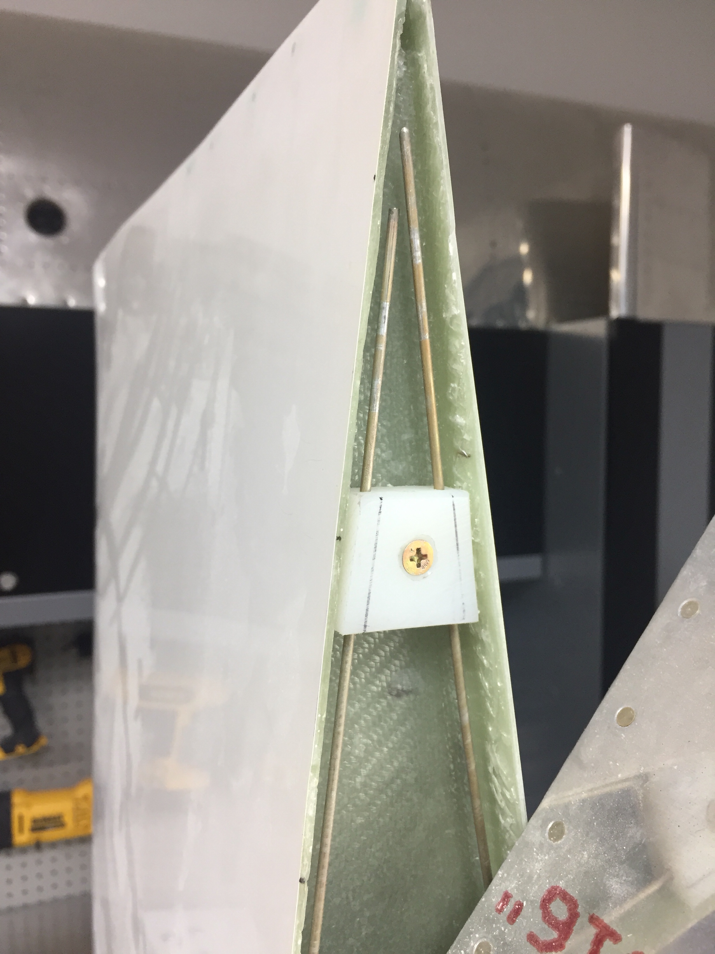
I also had to layup a small rib on the trailing edge to not only support the shape of the tip, but also provide a mounting surface for the hinge pin retainer. I used a trimmed block of delrin and nutplate to secure the pins. This keeps the pins inside the tip profile and thus unable to work themselves loose. They also butt up against a stop on the leading edge. I didn’t want to put a bend in them, as it’s very easy to use a drill and spin them in / out.

The only system component not installed in the wing is the OAT sensor which I’ll get with the avionics in a few months. That’ll be simple to put into an access plate and a string is still waiting to pull wires through the wing root.

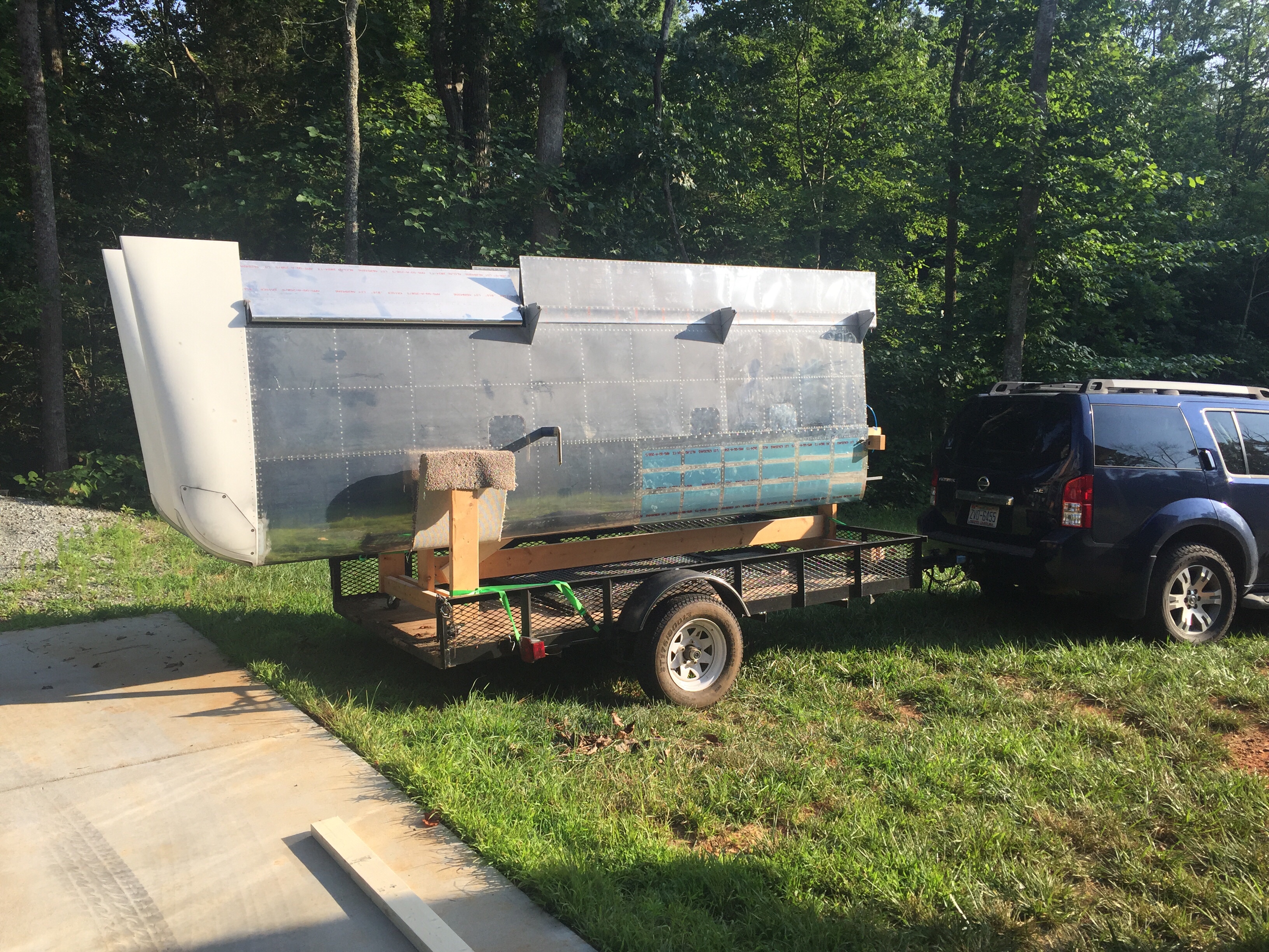
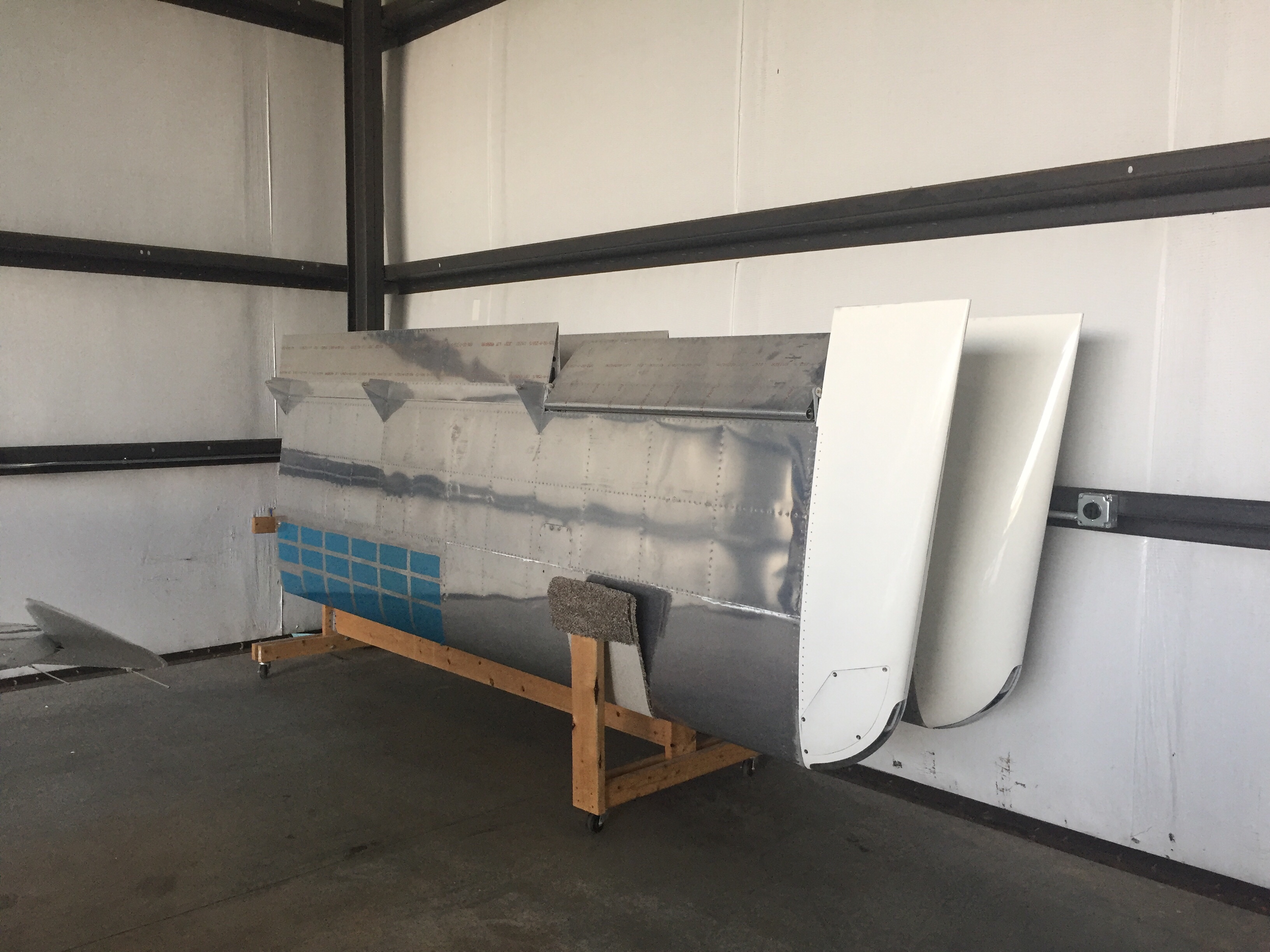
Since the wings are all complete, I need to get them out of the garage to make way for the finish kit and make me feel like I have real airplane parts in a hangar. My Diamond bros graciously offered a corner of their hangar for me to store the wings in until our hangar is available. So moving day came and anticlimactically went! It was like I designed the wing rack for the trailer and with Ron’s help, they rolled right on and off. We used a few tie downs and took our time on the 10 minute drive to the airport with no damage reported. I hope the fuselage move goes this smoothly!

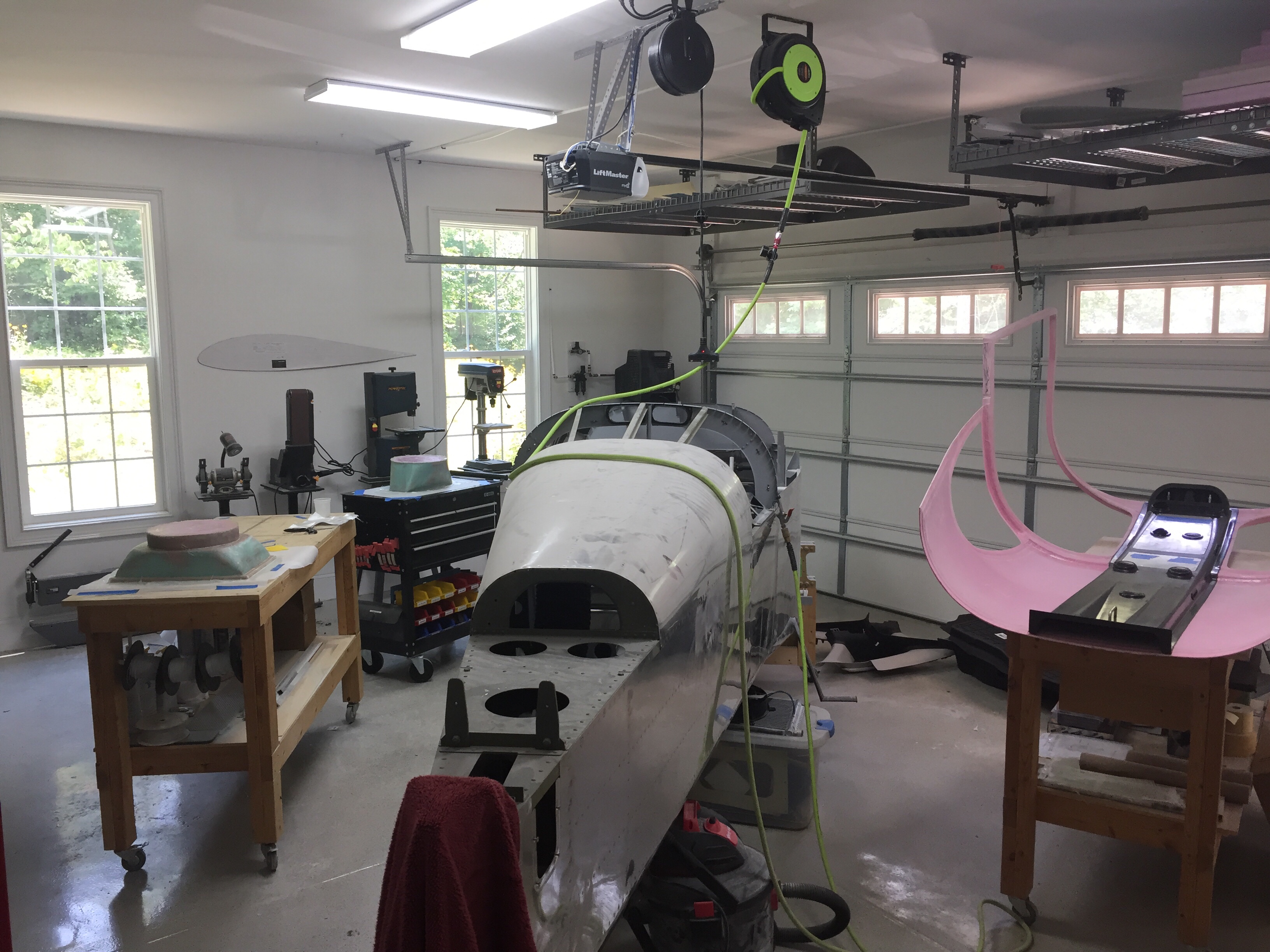
Bonnie the Bonanza is now babysitting RV wings. Meanwhile, back home the shop has so much room for activities such as finishing the cabin top and getting ready for the finish kit and cowling which are due to arrive early August.

Quit flapping around

One of the last projects before the cabin top section is the flap torque tubes and motor.  Switching gears back into progressively drilling holes in steel is a bit tough and time consuming.  Lots of oil, lots of shaving, and patience is needed.  I had to open up the holes with a deburr tool through the side panels which the tubes pass through.  All fairly straight forward, however, and everything lined up very well in the end.  The motor was an easy mount and at the end, I had to hook up a 9 volt battery to test it all out.  Pretty cool seeing systems start working in the airplane!

This was several evenings in the shop getting it all fabricated and I quickly realized that there is nothing left to do than put the cabin top on!  I also realized that while the cabin top is a massive amount of work, it’s also a good time to order the finish kit since having the doors is key to getting all the big work done on the fuselage.  I’m looking forward to getting the big pink thing down from the ceiling and on the fuselage!

Sit back and relax

After spending three months away from home and the build, I am happy to be back from my TDY and immediately got back to work on the project.  The time wasn’t completely wasted build-wise though, as I spent a lot of time researching, studying, and designing the remaining aspects of the build.  The biggest accomplishment was the finalization of my electrical schematic, specifically the power distribution.  I haven’t quite finished the final touches on the Visio product, however, the design is now on paper (digitally) and vetted through several external sets of eyes.  I’ll detail it more in a later post.

I also spent a lot of time talking with engine shops and builders.  I narrowed down all of my requirements to get quotes and solicited those out to several shops.  After lots of discussion, emails, and phone calls, I am really excited about what Aerosport Engines out of Canada has to offer.  They are one of only a few who can still get a new “kit” engine from Lycoming so all parts are brand new but not assembled.  That’s important to me since we’ll be adding SDS EFI and some other tid bits that would differ from a stock IO-540 without wasting money.  They also offer a build class that allows you to spend a weekend helping assemble your engine and learn a lot through the process.  I plan on turning it into a little vacation with my dad to build up our engine.

That’s plan A for the power plant.  Plan B is much more exciting but I’m keeping that one under wraps for a bit longer.

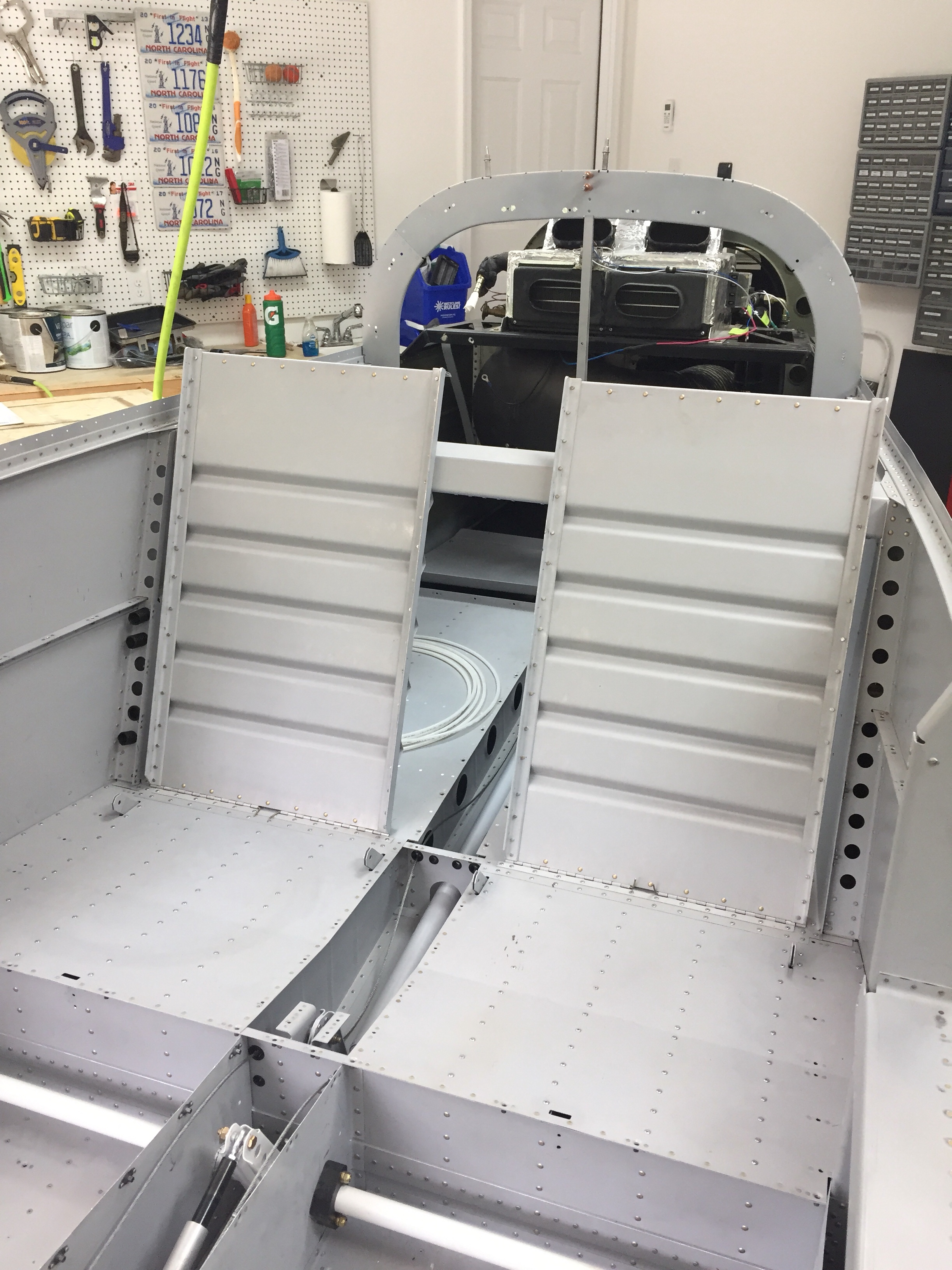
Back in the shop, a big morale booster is getting the rear seat back panels installed.  These were super simple to make with the panel and L angle.  The piano hinges were already cut as part of the floor / bulkhead and the backs fitting were a nice confirmation that I did it correctly way back when.  The seat backs show how roomy the 10 really is, not only in the passenger area but also behind them in the baggage area.  We are very excited about filling it all up with people, puppies, and packs for the adventures that lay ahead.

Closing the gaps

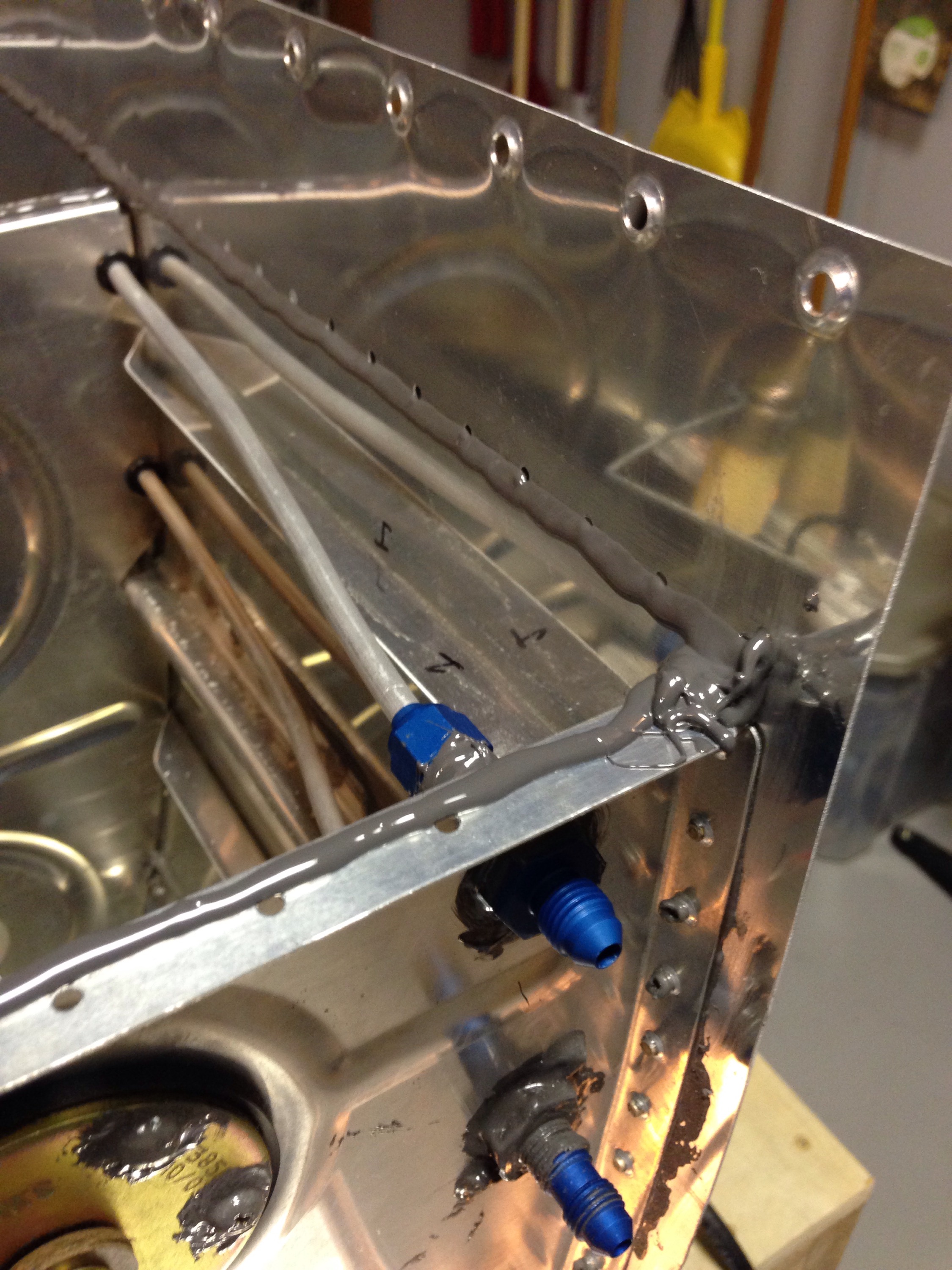
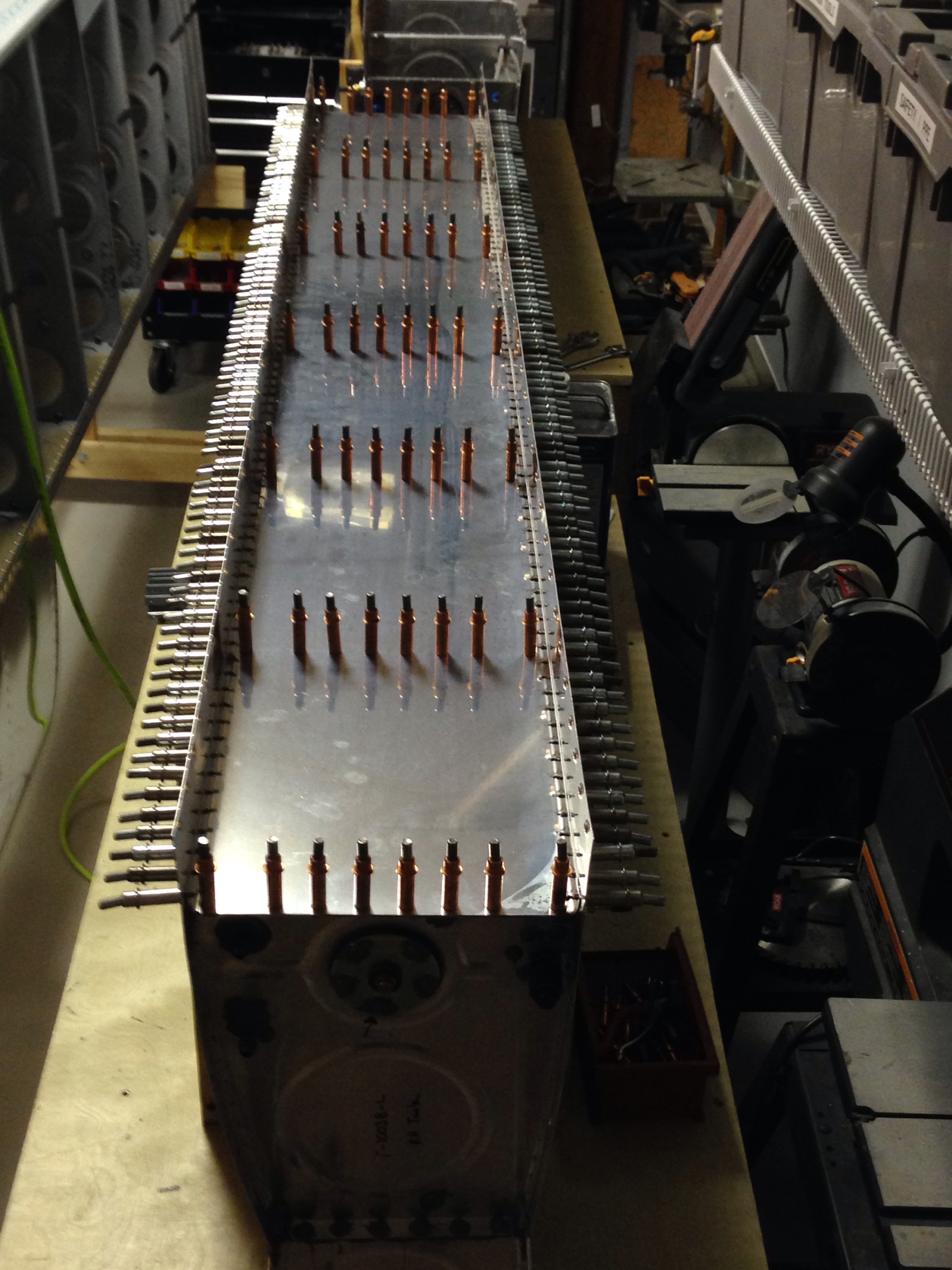
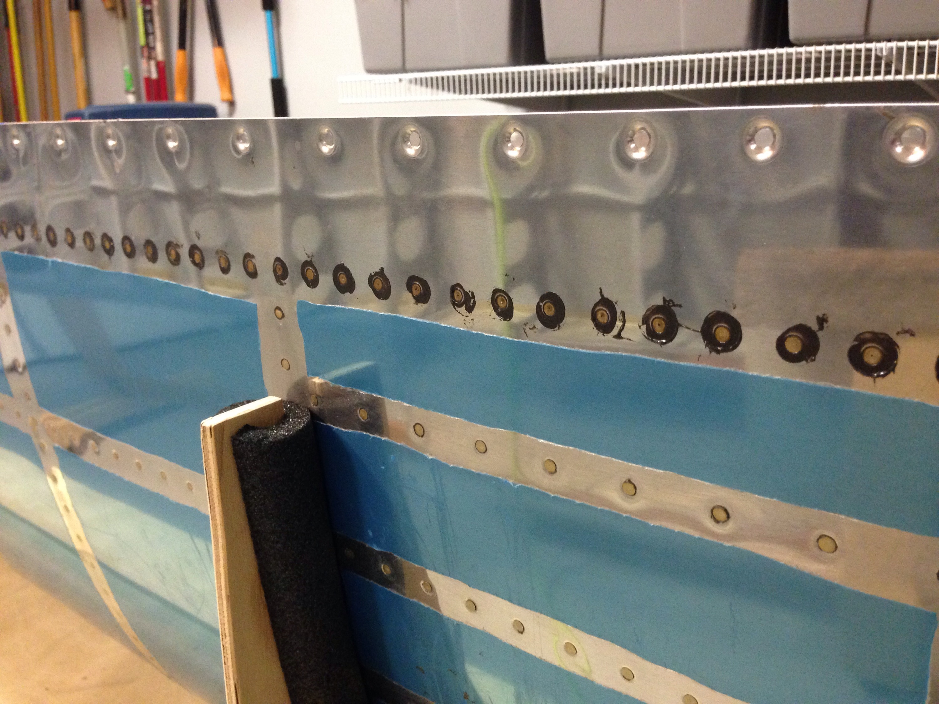
The final step for the tanks is to seal the rear baffle in place.  This is always a bit tricky as you have to put a bead of proseal and then place the baffle in using it as a squeege and hoping that it seals internally.  If not, it’s a tough fix as you now can’t get inside the tank.  

Using the applicator gun helps here get a nice even bead of proseal in place.  Putting a cleco in every hole, I let it set up overnight as usual and came back the next day to finish riveting.  With the perfect world scenario, the rivet line would be outside of the wetted fuel area.  However, if there might be a leak, I decided to continue my habit of wet riveting.  This would make it easier to seal from the outside.

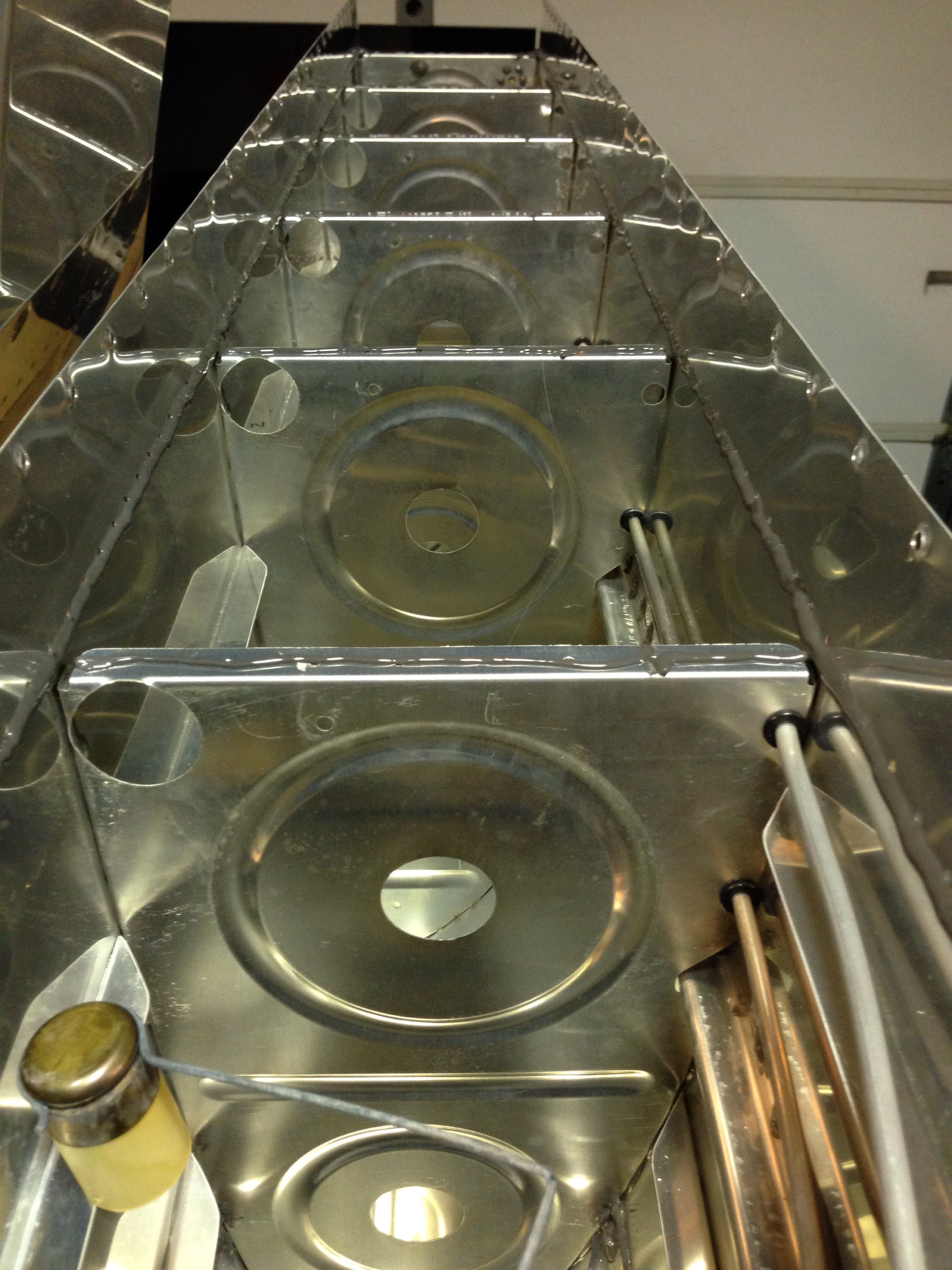
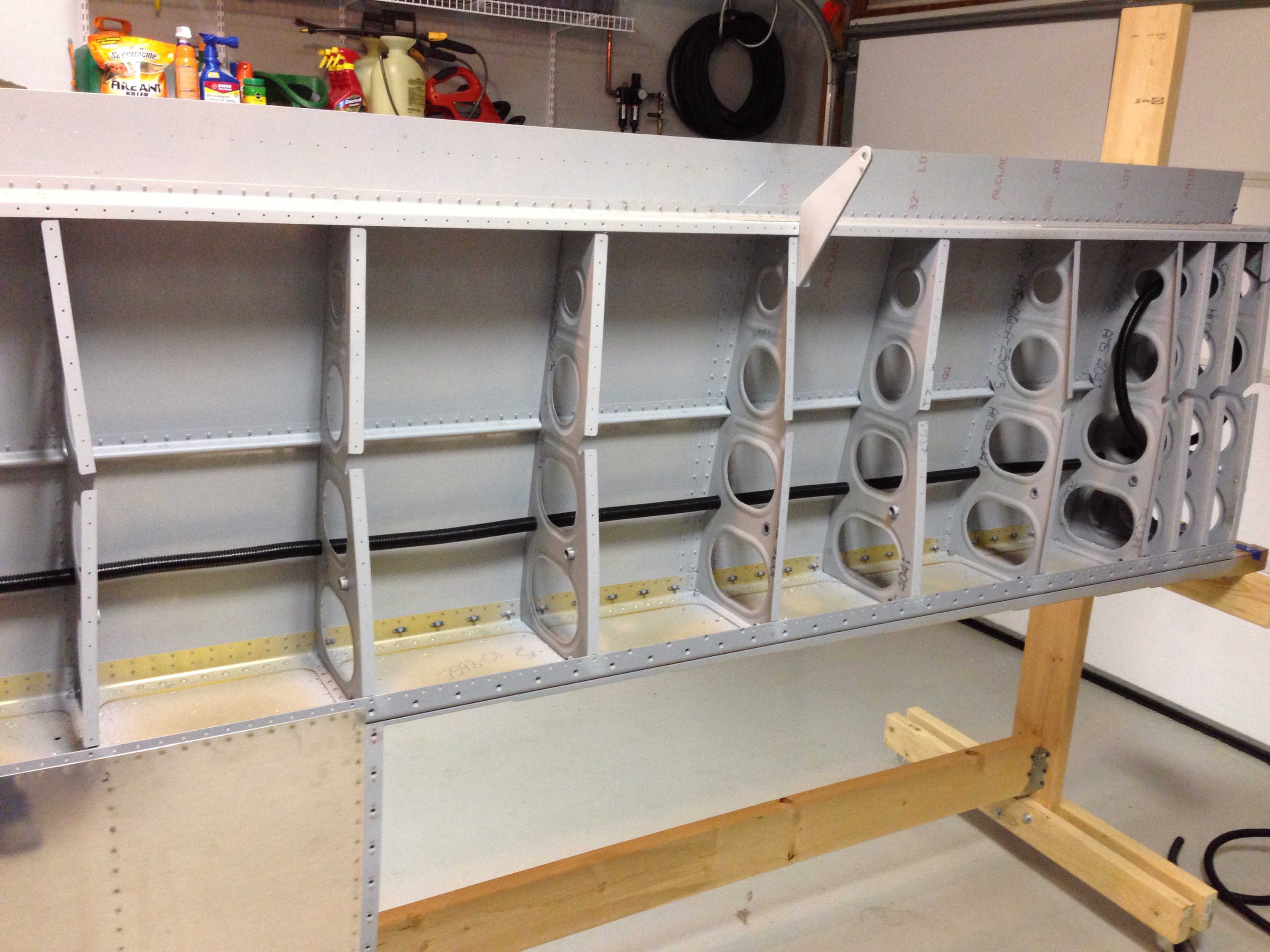
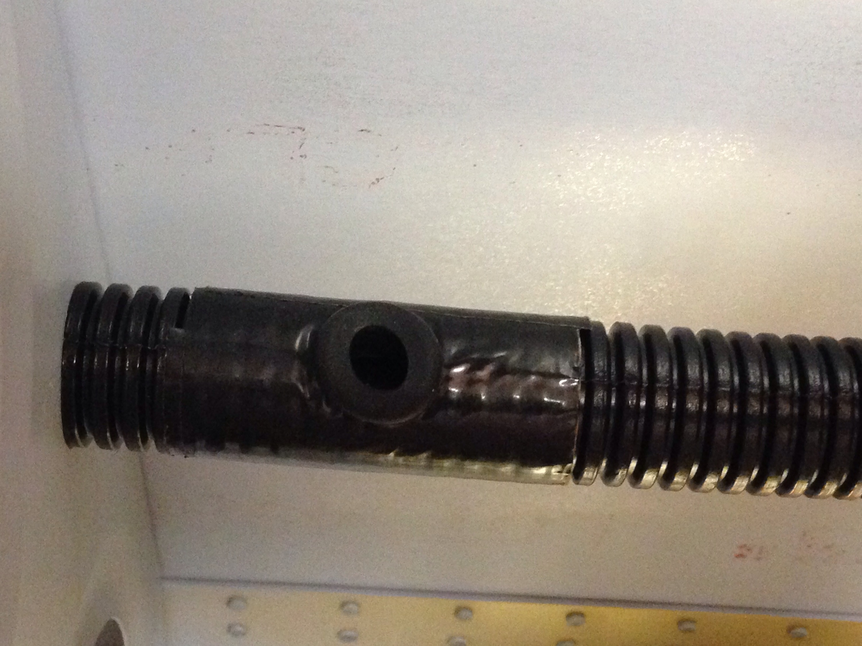
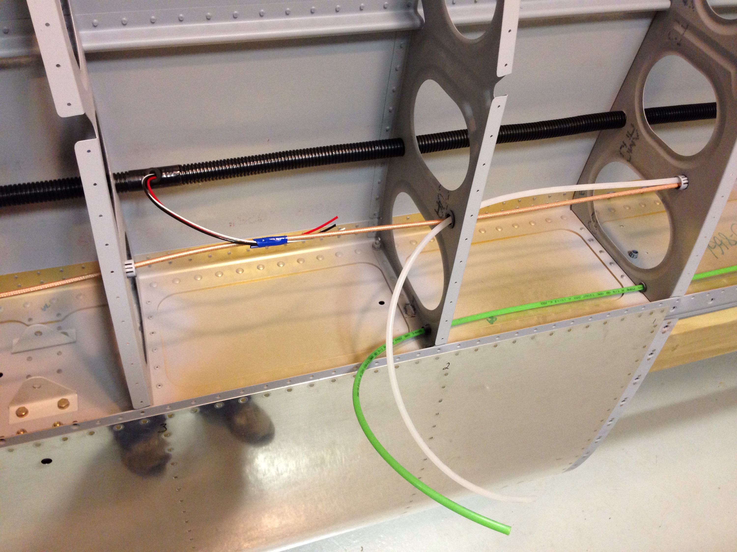
While the tanks set up, I turned to preparing the wing for close up.  I want to follow other’s advice on finishing everything inside the wing before riveting the bottom skin on.  Wiring is a big part of that so I ran the first bit of conduit.  This is a real pain in the ass.  Yes, I said pain in the ass.  It’s my blog, so I can say it.  And it’s true.  The corrugated conduit from Van’s is a royal pain to pull through.  You basically have to pop each ridge through the hole.  Starting from the middle of the wing, I pulled inboard and outboard to minimize the number of ribs the conduit has to be pulled through.

After a lot of sweating and some worn out hands, conduit is in place.  At the locations where wiring will exit the conduit, I cut a hole after wrapping the conduit in duct tape.  This made it a bit more sturdy and allowed the gromet to stay in place better.  The rubber gromet will prevent any chafing.  I tacked this in with a little silicone to help keep in place for the long term.

I will be terminating all connections at the wing root for a couple of reasons.  First to allow me to do as much wiring and plumbing as possible early on in the build process.  Second, it will allow me to keep the wings off of the fuse down the road as well.  I went ahead and pulled string through the conduit from the wingtip and seperately each exit to the wing root.  I then ran wiring for the heated pitot probe along with tubing for the pitot and angle of attack hook ups.  The wiring for the aileron trim servo and coax for the two Archer antennas in the wingtips were all secured for later connections.

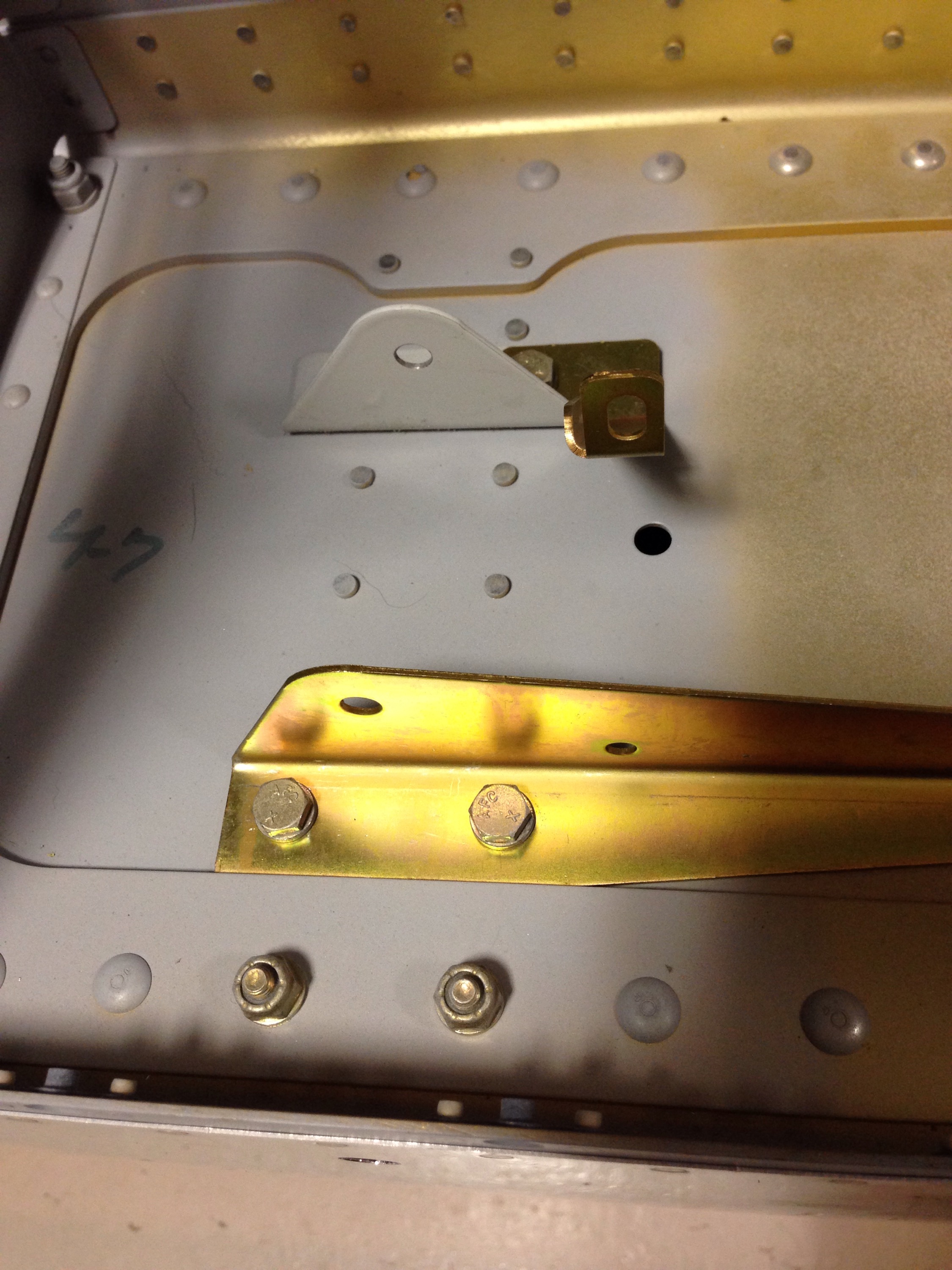
Finally, I installed the newly arrived servo mount for the autopilot roll servo.  The same bracket fits Dynon and TruTrak servos, which covers the spectrum for Dynon or AFS avionics.  I’ll be purchasing the servo down the road.

Decisions, Decisions

Over the past couple of weeks, I’ve done a lot of work on making decisions based on a lot of research and discussions. This might be a boring read, but I want to document my decisions for the build process and keep my own thoughts straight.

First the engine. It’s a big decision and complicated. I’ve decided to overhaul a used engine and do most of the work myself with the help of a few experienced professionals. There is a local guy who has built many engines for race planes and has a reputable engine shop that has offered to be a technical resource and allow me to use his facilities and equipment. While this won’t be for a while, our hours long conversation has reassured me of this approach vs. buying a new engine. He also advised me on which variants and the things to look for in a run-out or used core. So I’ll be keeping an eye out for good deals on eBay, Barnstormers, etc. over the coming year or so and hopefully make a purchase when the right opportunity comes along.

Building my own engine will also allow me to customize it with the options efficiently and cost effectively. I have committed to running the full EFII electronic ignition and fuel injection system. I like the ease of operation the system provides and most of all, the efficiency of the system. I will use the dual ECU option to provide redundancy for IFR operation. Combined with the Show Planes cowl, Flightline AC system, and possibly a horizontal induction pan, there will be some modifications required for sure. But this will be the airplane that I want and an efficient, modern platform.

It will also be heavily electrically dependant. I’m starting on the electrical schematic to include one main battery, one 70 amp alternator, one backup 30 amp alternator, and integrated back up batteries for the EFIS systems. Using the VPX Pro system will integrate my electrical loads with a few exceptions and provide a better insight into the health of the system.

More details to come on all of these decisions, but it paves the way for planning purposes and at least lets me get started on some of the systems side of the build.