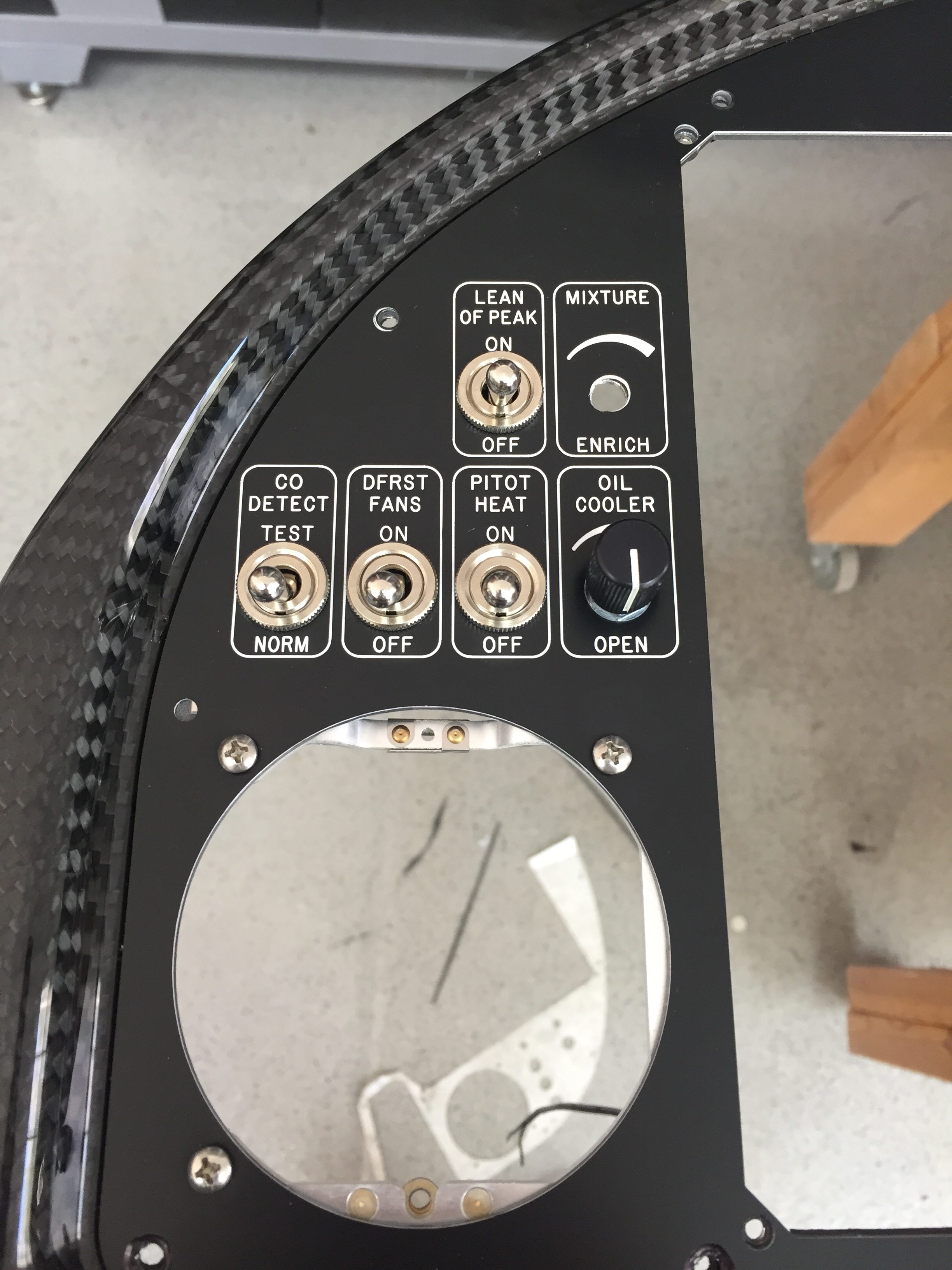
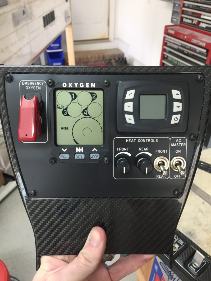
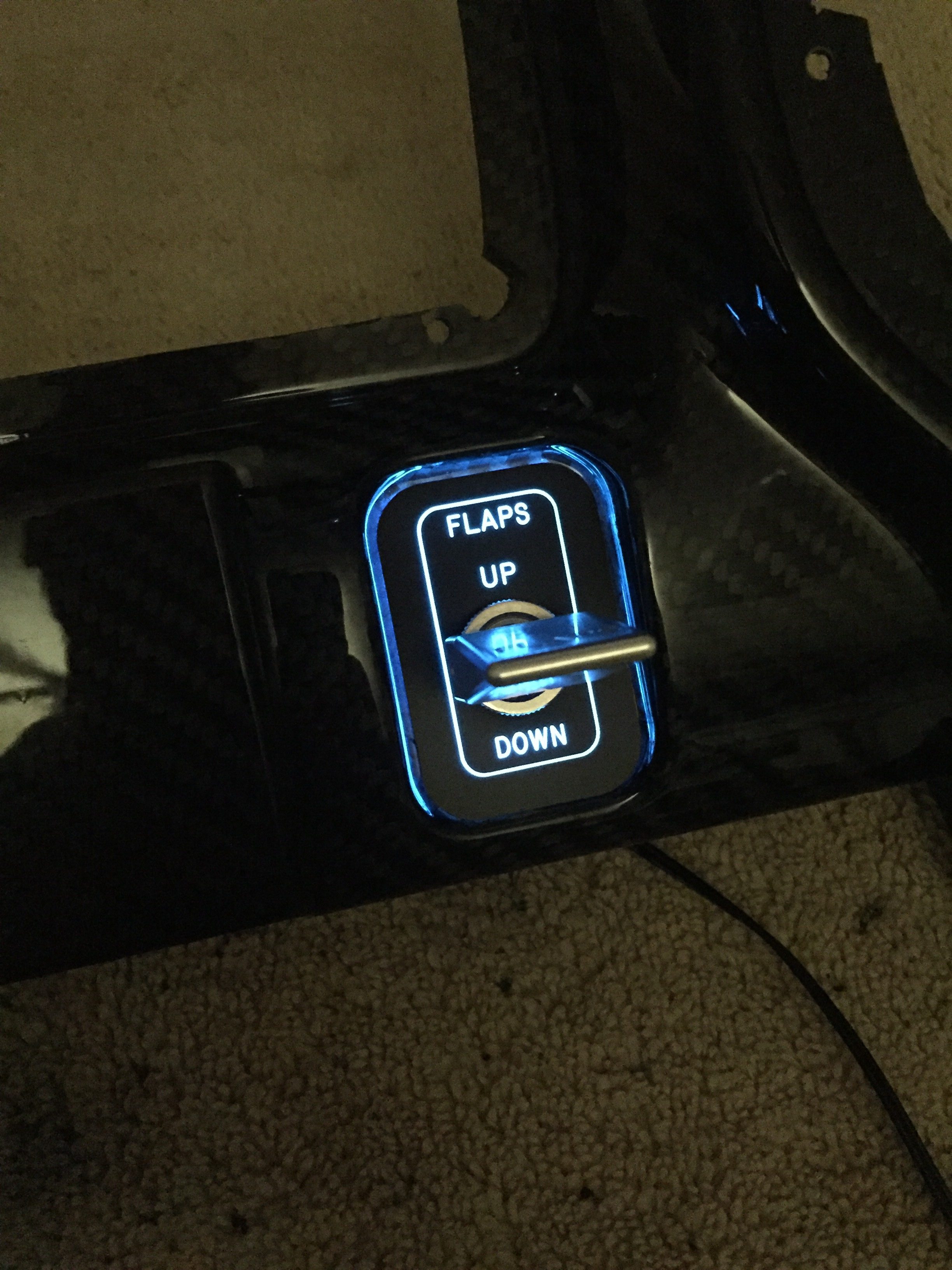
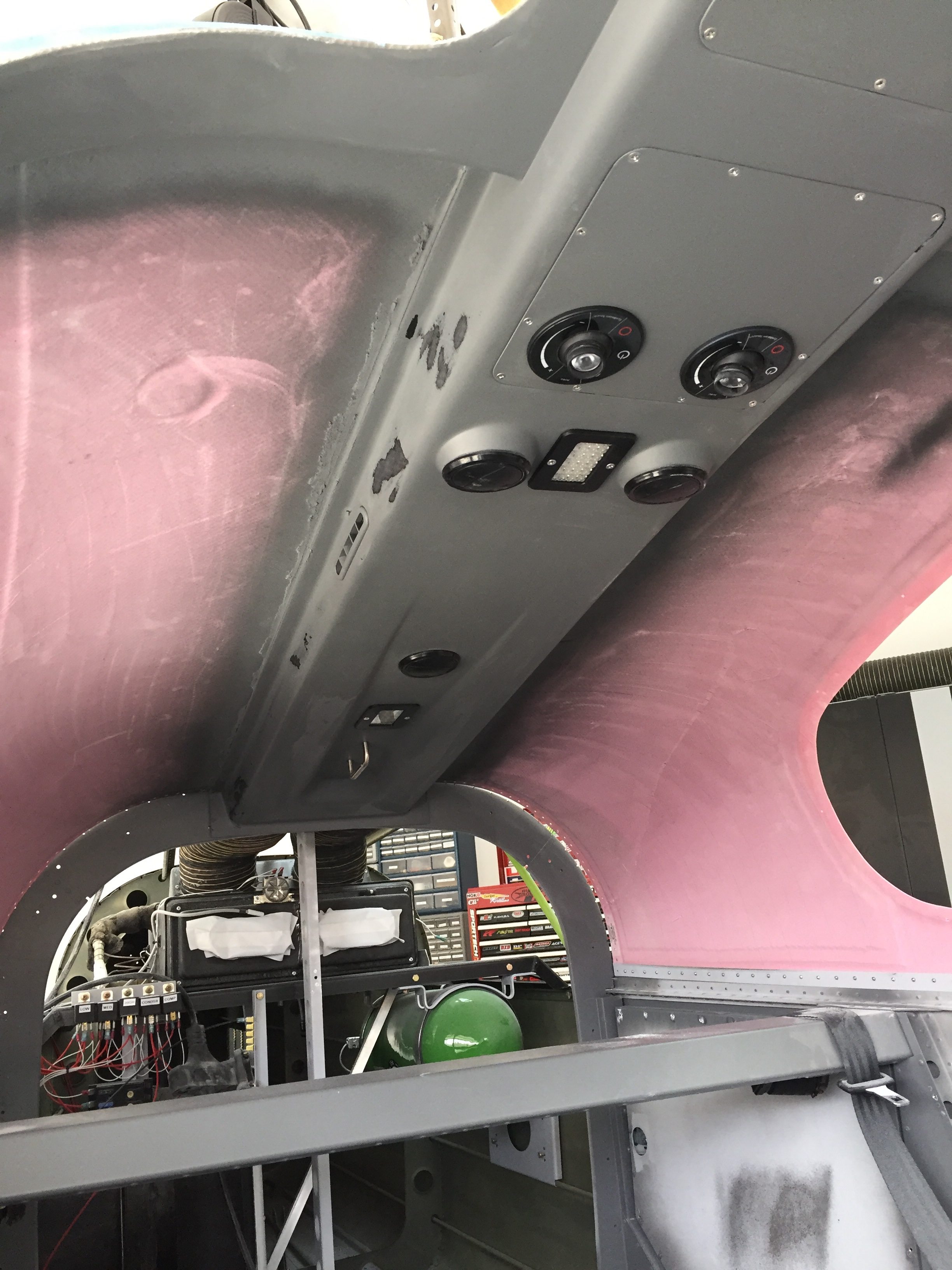
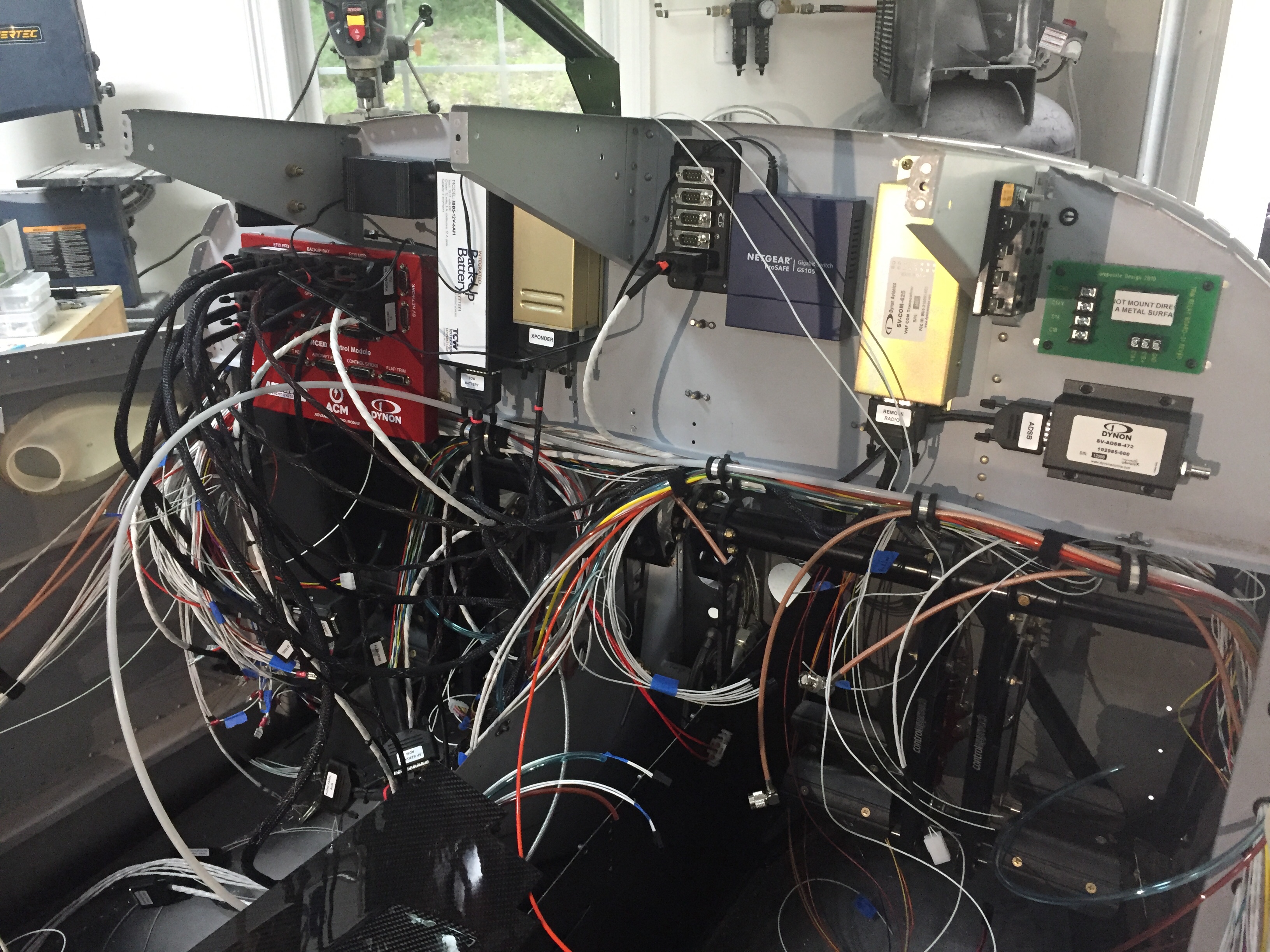
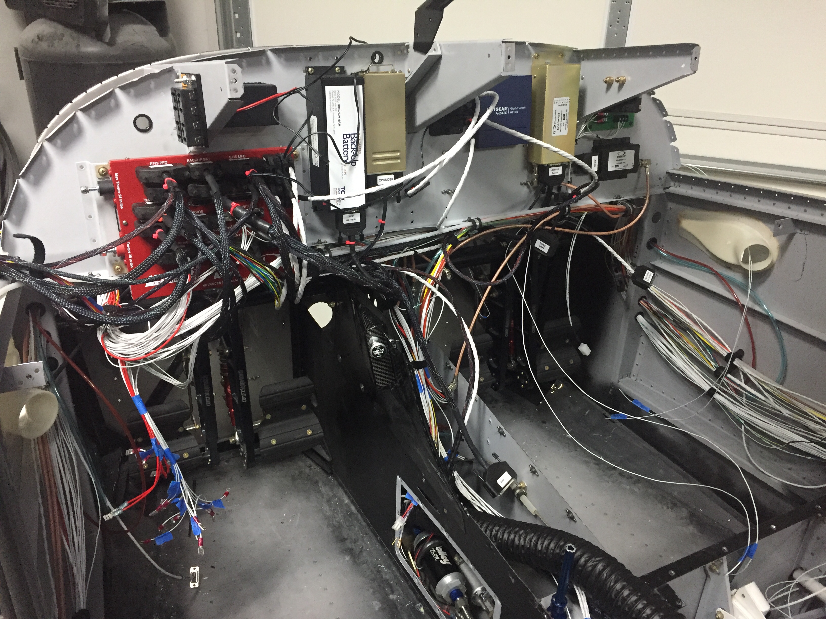
More wiring plus some more wiring then more wiring

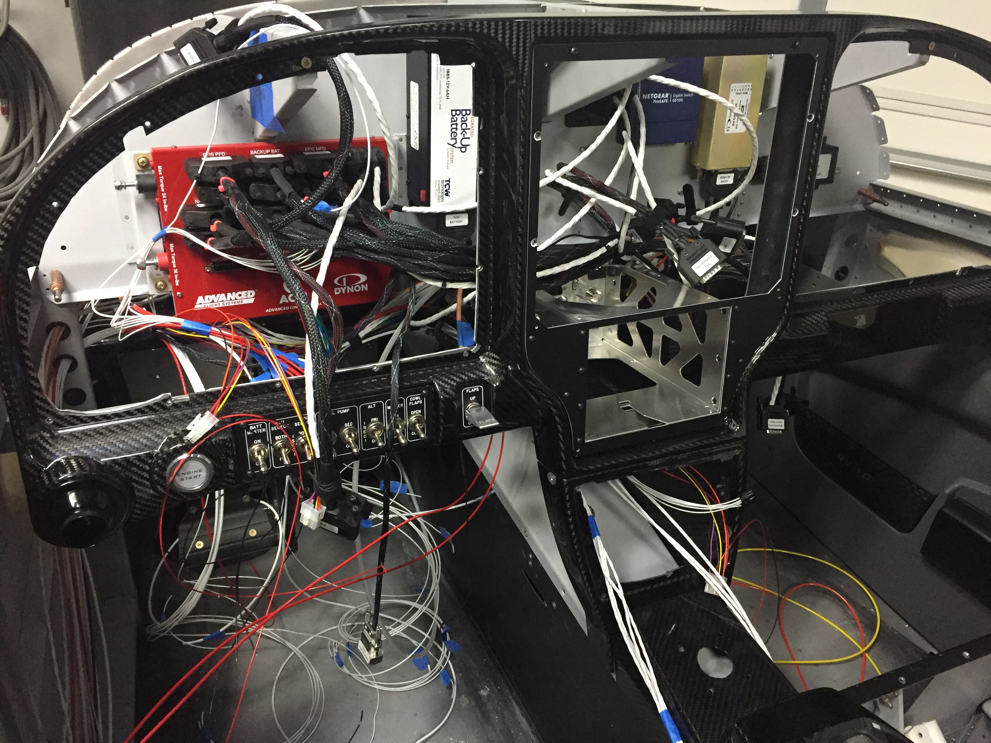
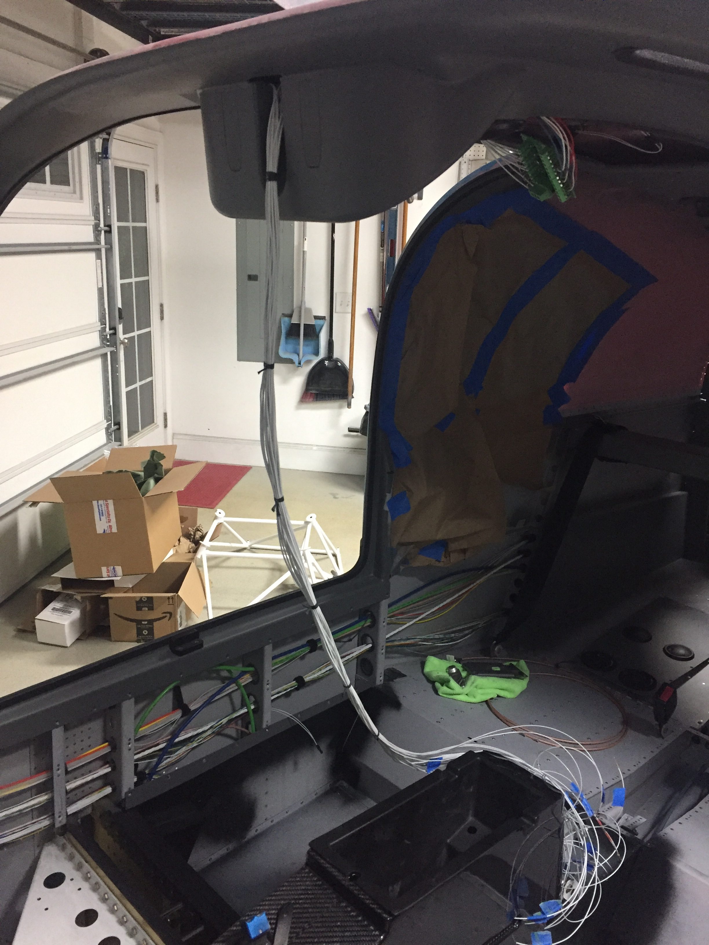
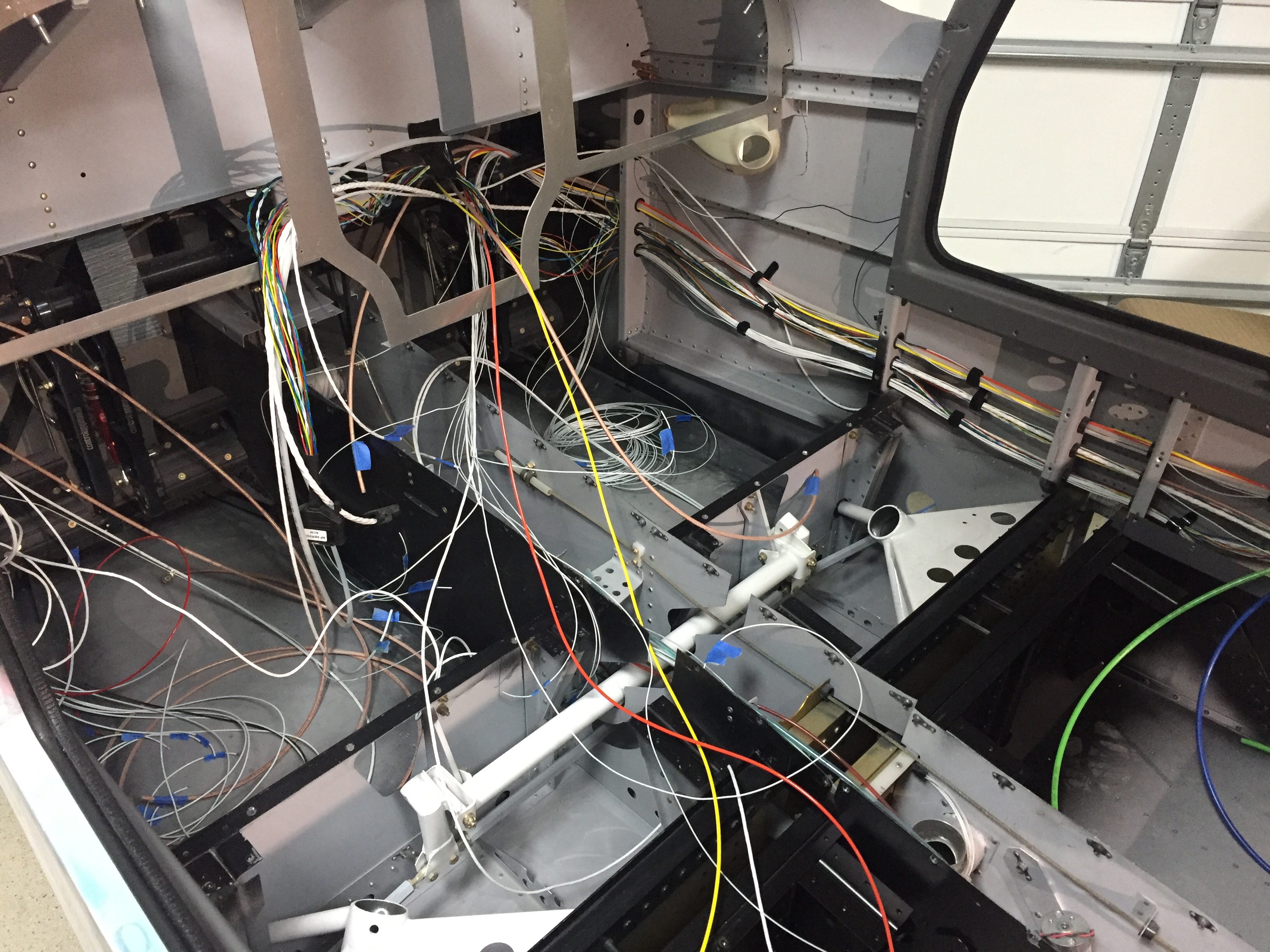
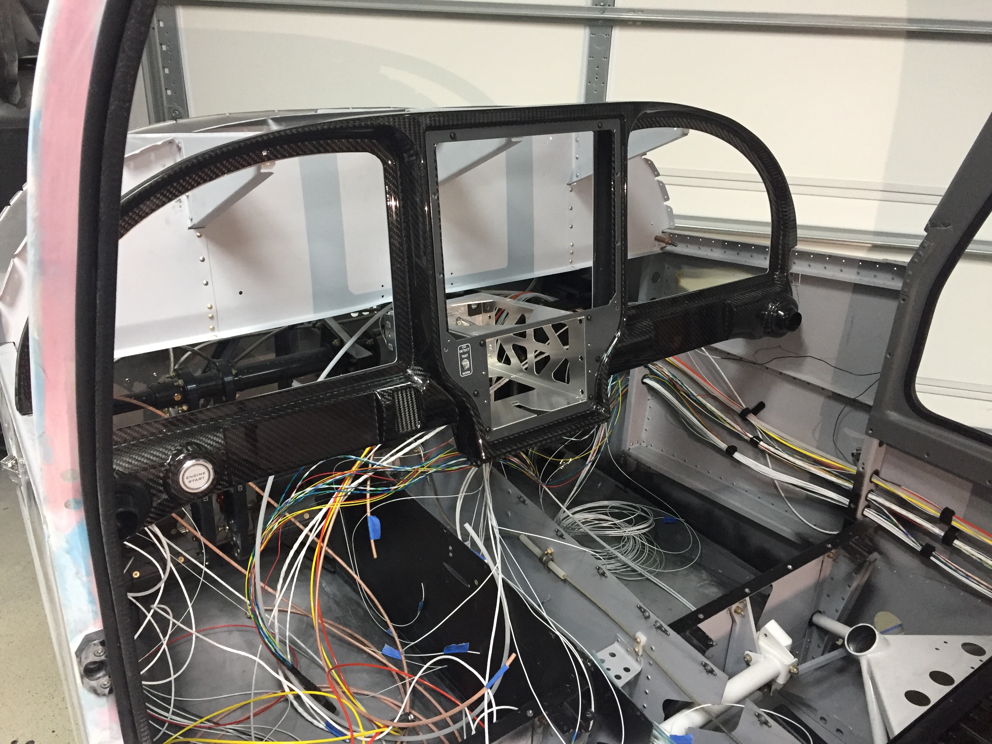
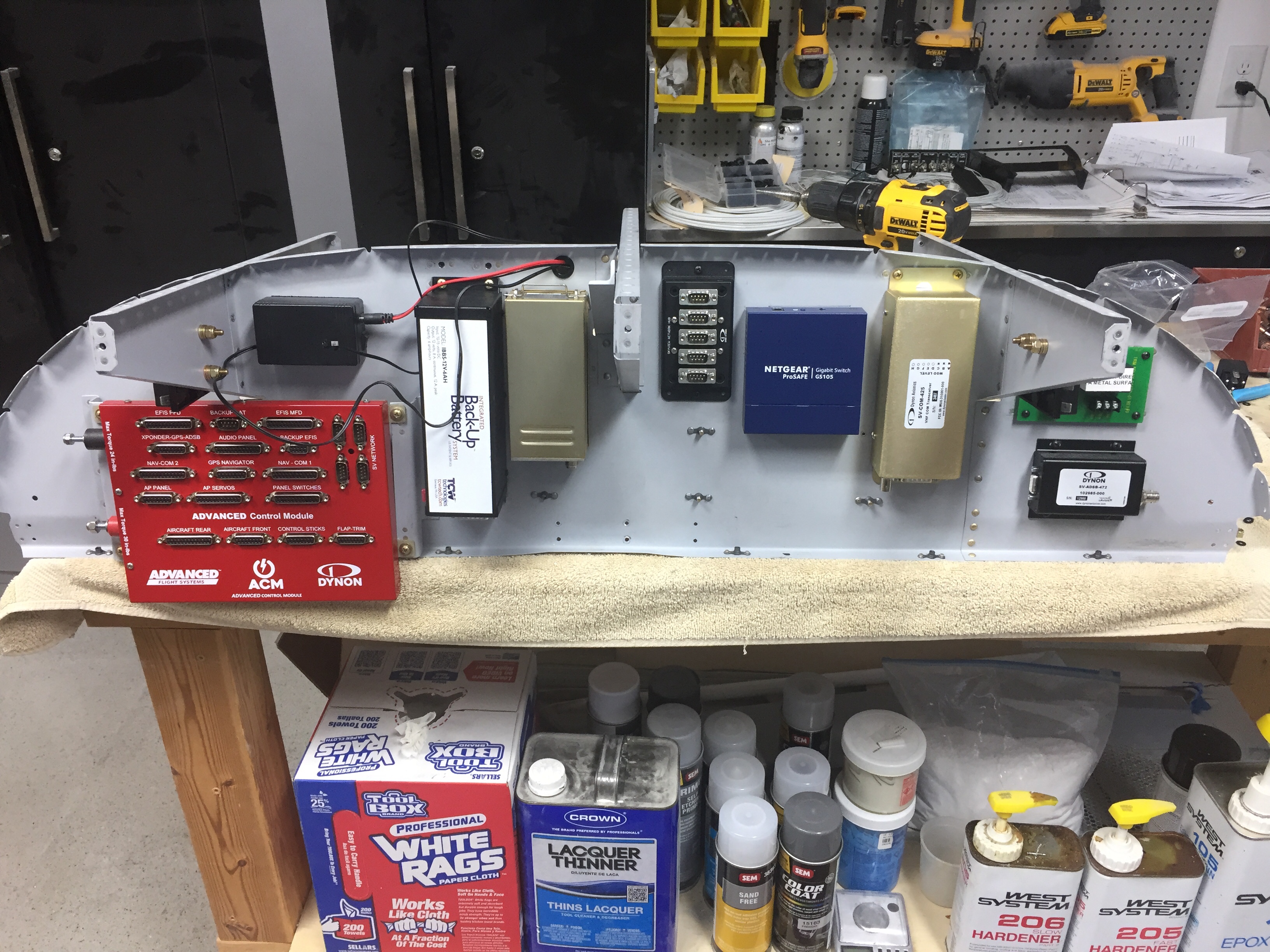
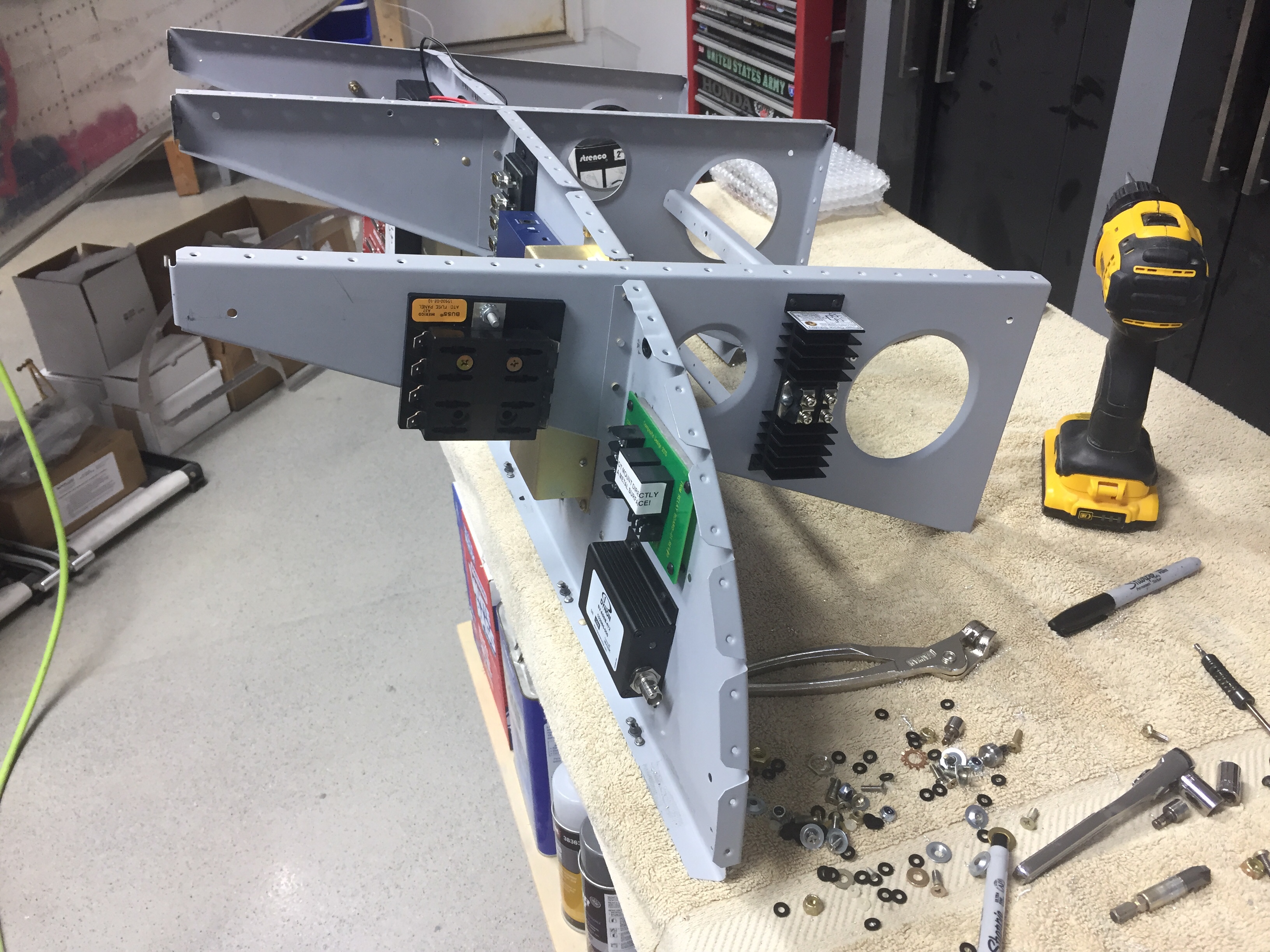
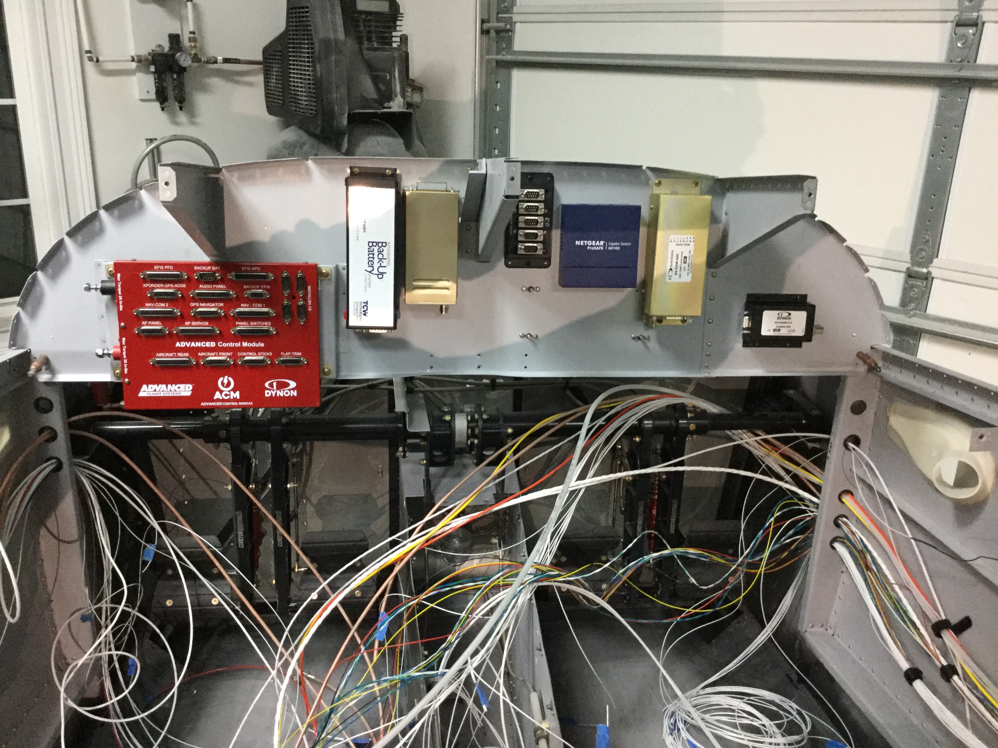
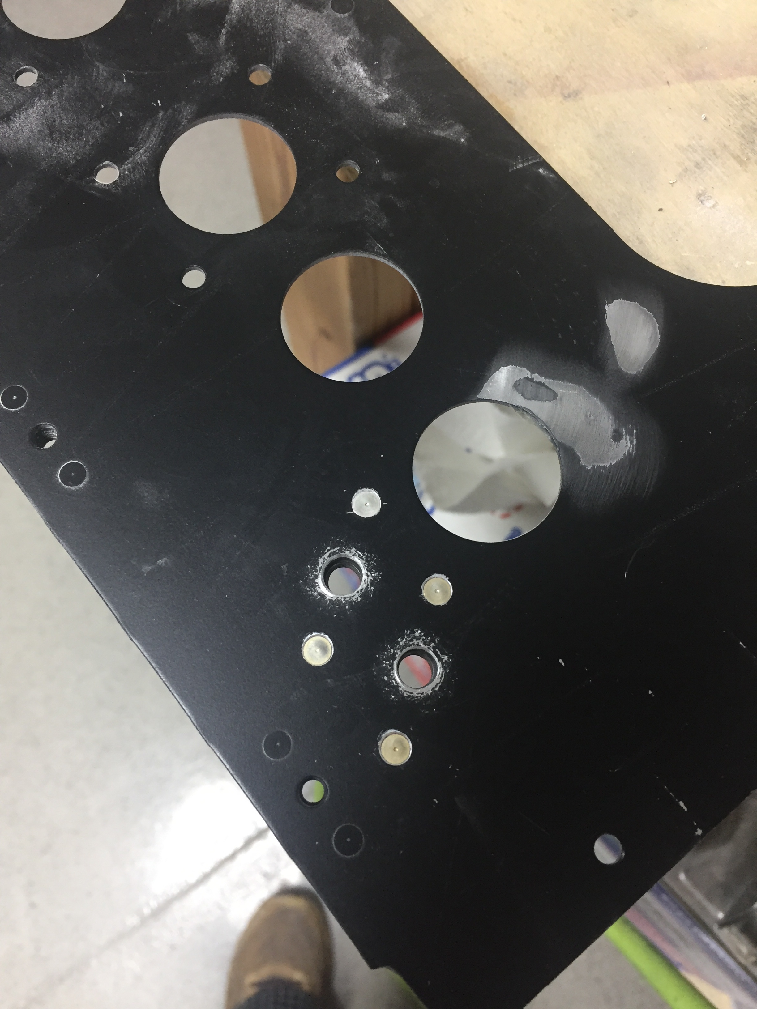
Wiring continues as I think I’m nearing the end only to discover more runs that need to be installed.  I reworked the nutplates for the back up battery on the subpanel and have the subpanel back on the fuselage temporarily to continue bundling wire runs.  The amount of wire I hadn’t thought of is a little higher than I was expecting, as I thought I had a good handle on the “pre-work” for the avionics.  Rudder trim board, a few relays, the lighting control module, and a few others all popped up as I put components in place.  I’m working hard to keep the runs neat and tidy as I go.  I’ll ziptie everything in place once I feel that I’m done with wiring but I’m sure I’ll forget one or two and need to redo the zipties.
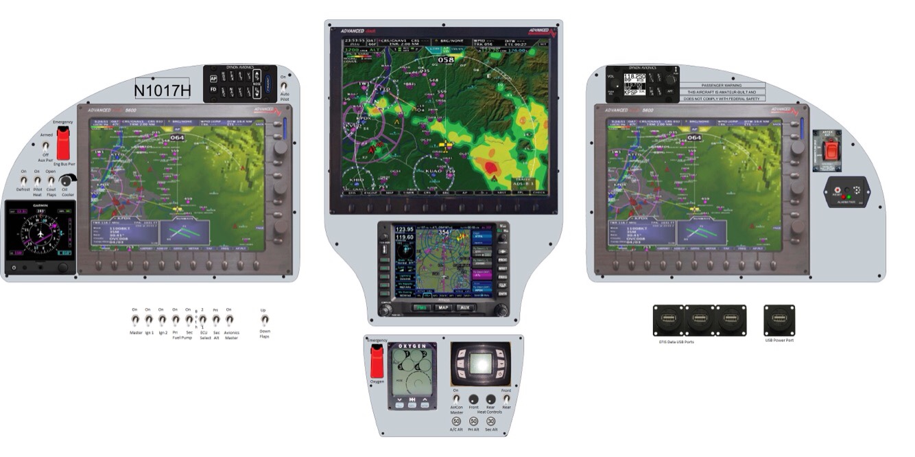
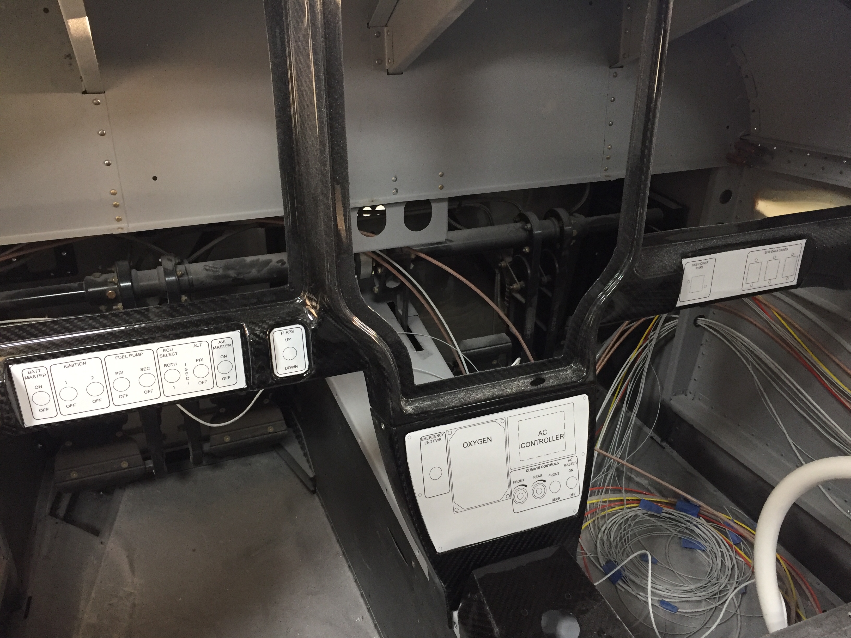
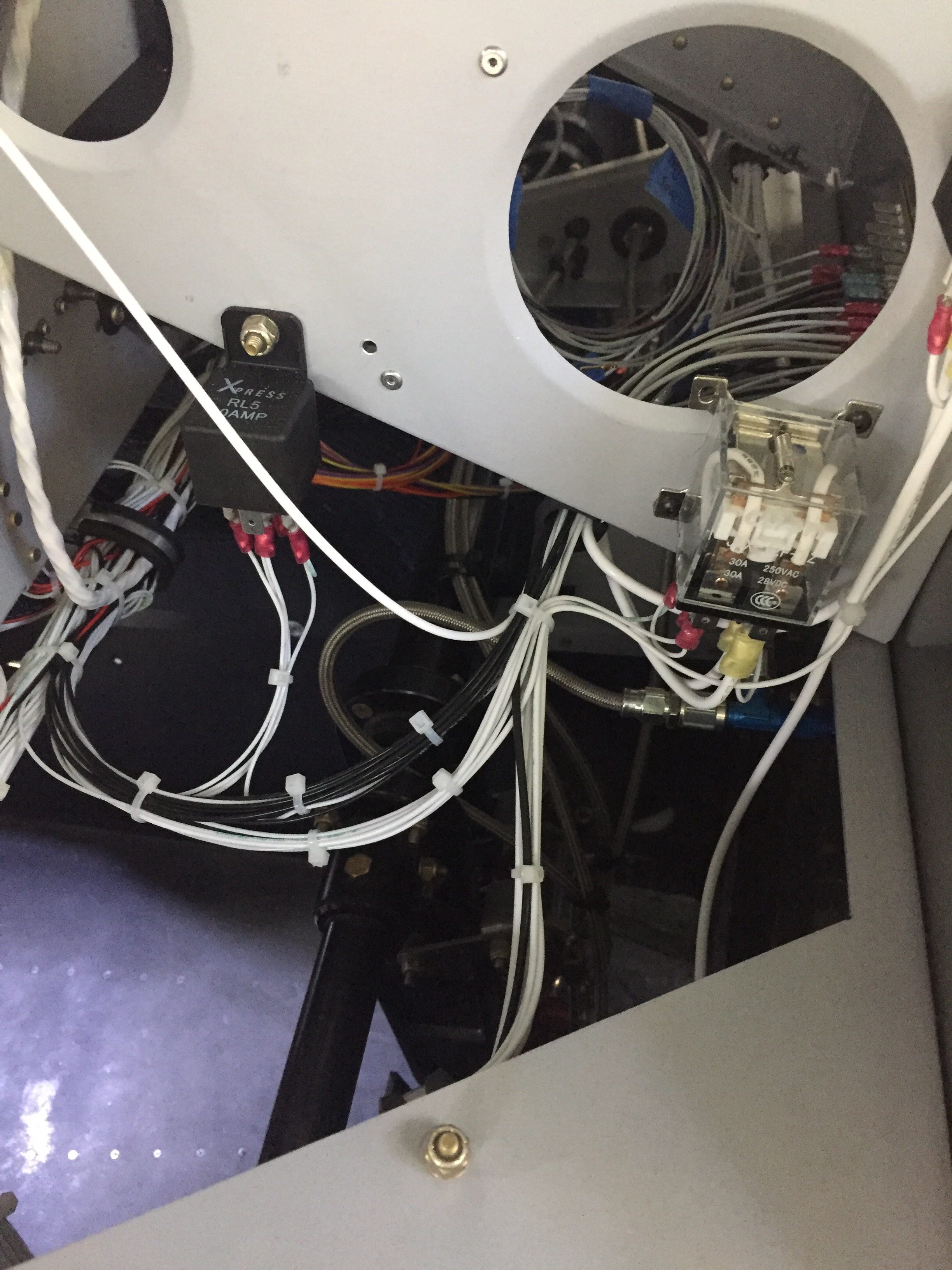
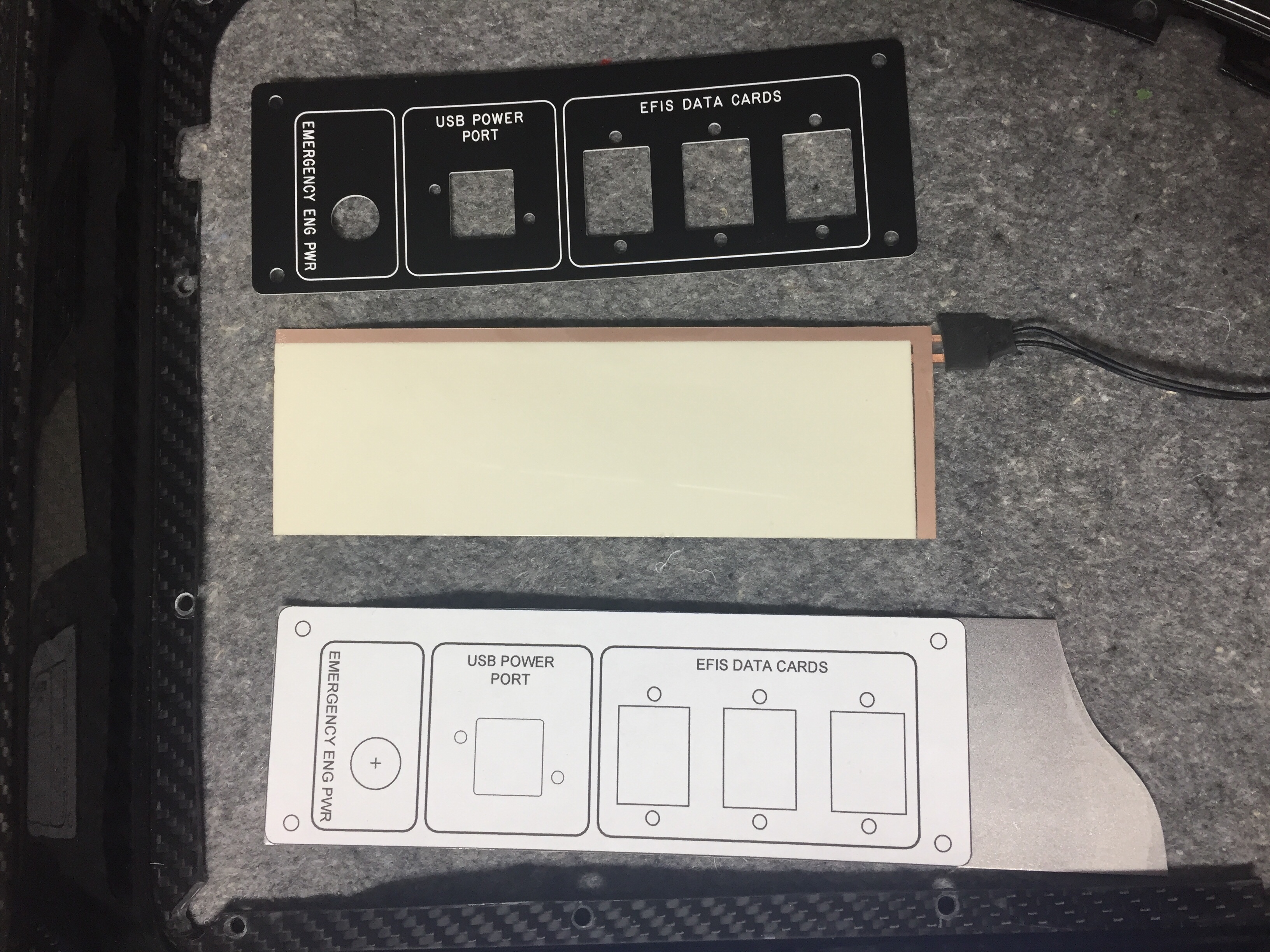
I had to have one of my panel overlays re-etched since I decided to add an emergency power switch for the engine bus.  I had originally designed a two relay system that would automatically provide backup power directly from the battery to the engine fuse block (bus) should the main power supply fail (master contactor, etc.).  A three position switch would be off, armed, and test allowing the system to be tested before flight.  I decided it was too complicated and didn’t design the panel or schematic for it, but now regret that.  Essentially, it is only redundant for the master contactor, but now that I’m visually seeing the path of power all going through the contactor as a single point of failure, I want a backup.  So I’m running a DPDT 40 amp relay from the battery to the engine buss.  I had considered a diode which would isolate a short in the main system but decided to not plan for multiple modes of failure.  The switch will be red guarded and the second pole will have be an input for EFIS annunciation to verify the relay’s activation.
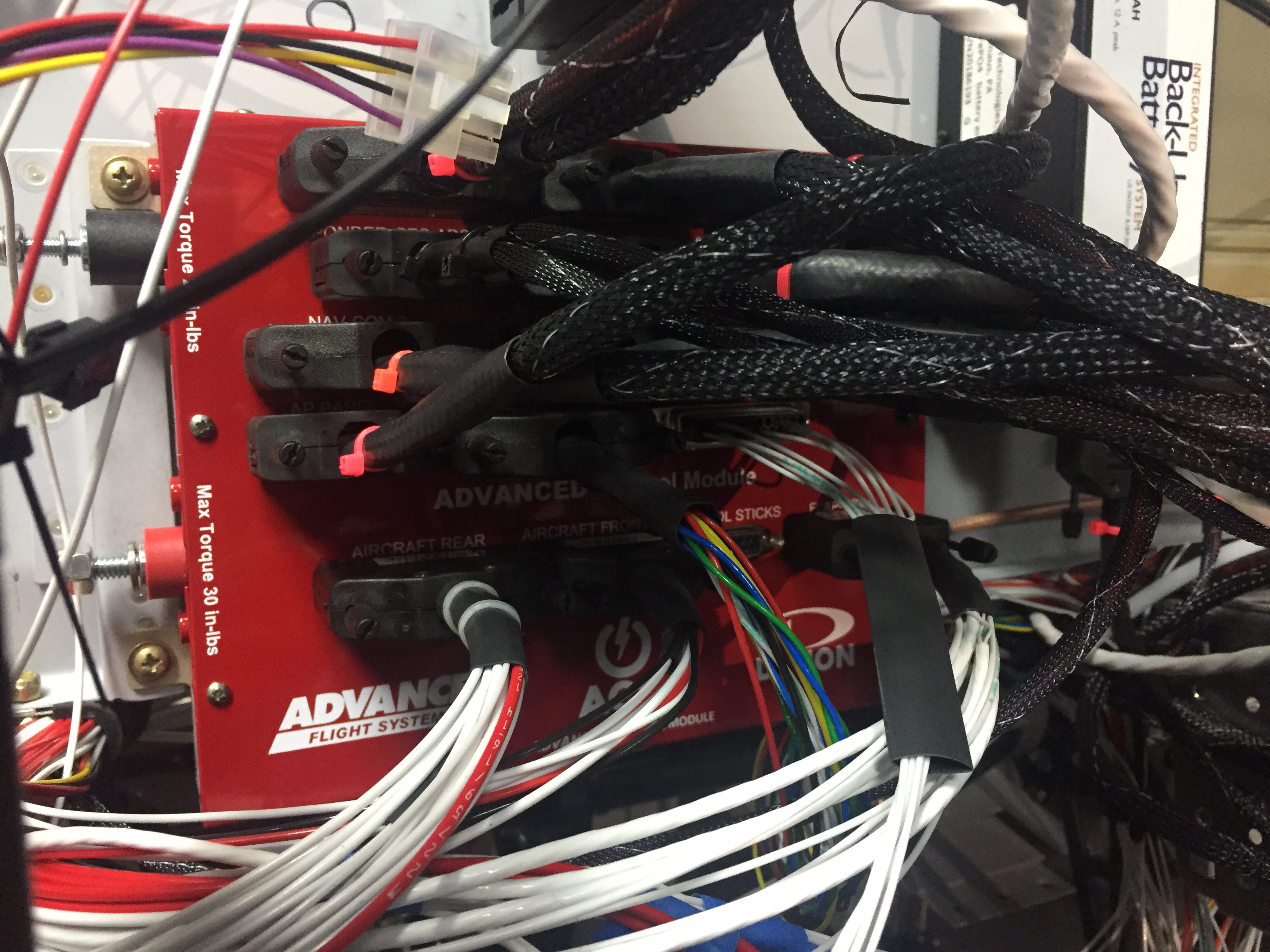
I also forgot about the control stick wiring, which is the last connector needed for the ACM to be fully plugged in.  I don’t want to fit my control sticks until I rig the surfaces, as the throw of the stick as is now is greater than when properly rigged.  So I pulled wires, labeled them, and terminated them on the ACM side.  This is when I realized I went a bit overboard on the number of switches on the sticks.  I had planned on the typical Coolie hat trim switch, PTT, AP disconnect along with a TOGA, rudder trim toggle (horizontal orientation), and possibly a IDENT or comm swap.  It’s a lot, I know.  The Tosten grips have all that but I found out that I can’t use all of them!  The AFS/IFD setup doesn’t have an input for a TOGA as discovered after a lot of research and question asking.  The AP simply auto sequences the MAP based on the flight plan so no need for a TOGA.  The downside is not being able to go missed earlier than the MAP while on AP, something I’m used to in the Diamond with the G1000.  Not the end of the world.  I decided against a IDENT and comm swap switch as I just think they are not needed since I have to touch the panel anyway and I mean seriously, am I that lazy??  Ha, yes I am, but those two features still didn’t make the cut.  So, I wound up with three axis trim, PTT, and AP disconnect (AFS calls this CWS which it’s not but whatever).  A TOGA is reserved as a coming feature from AFS.
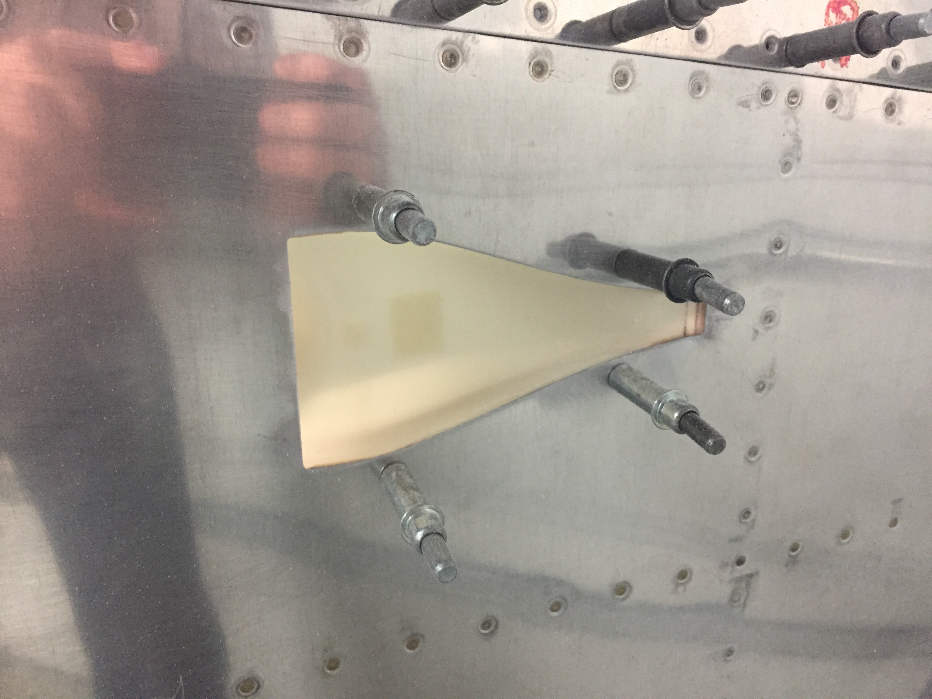
The GPU receptacle is also wired up now in its hidden location under the copilot’s seat.  I wired the GPU contactor such that it will power the full system but not charge the battery, as the Shorai will have it’s own balanced lead to connect the dedicated charger on the ground if needed.  Because I’m electron dependent, I will never jump a dead battery and take off, so no need for external access.  The GPU will be in the hangar for maintenance and/or learning the avionics.  I cut a little flap in the seat foot well wall and mounted the receptacle to the seat rail support.  It worked great and will have one bolt on the seat bottom to help secure once that area is all complete.
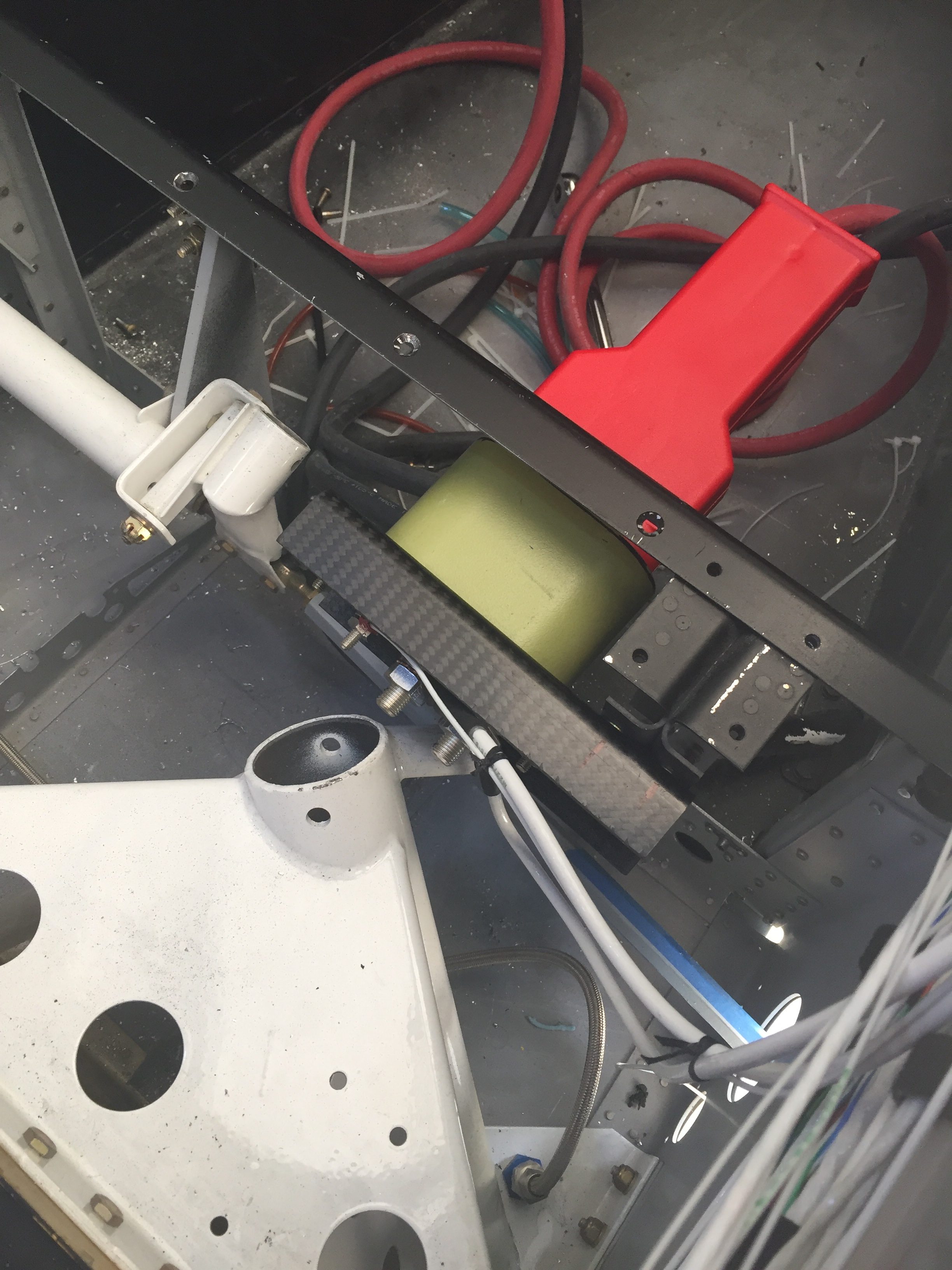
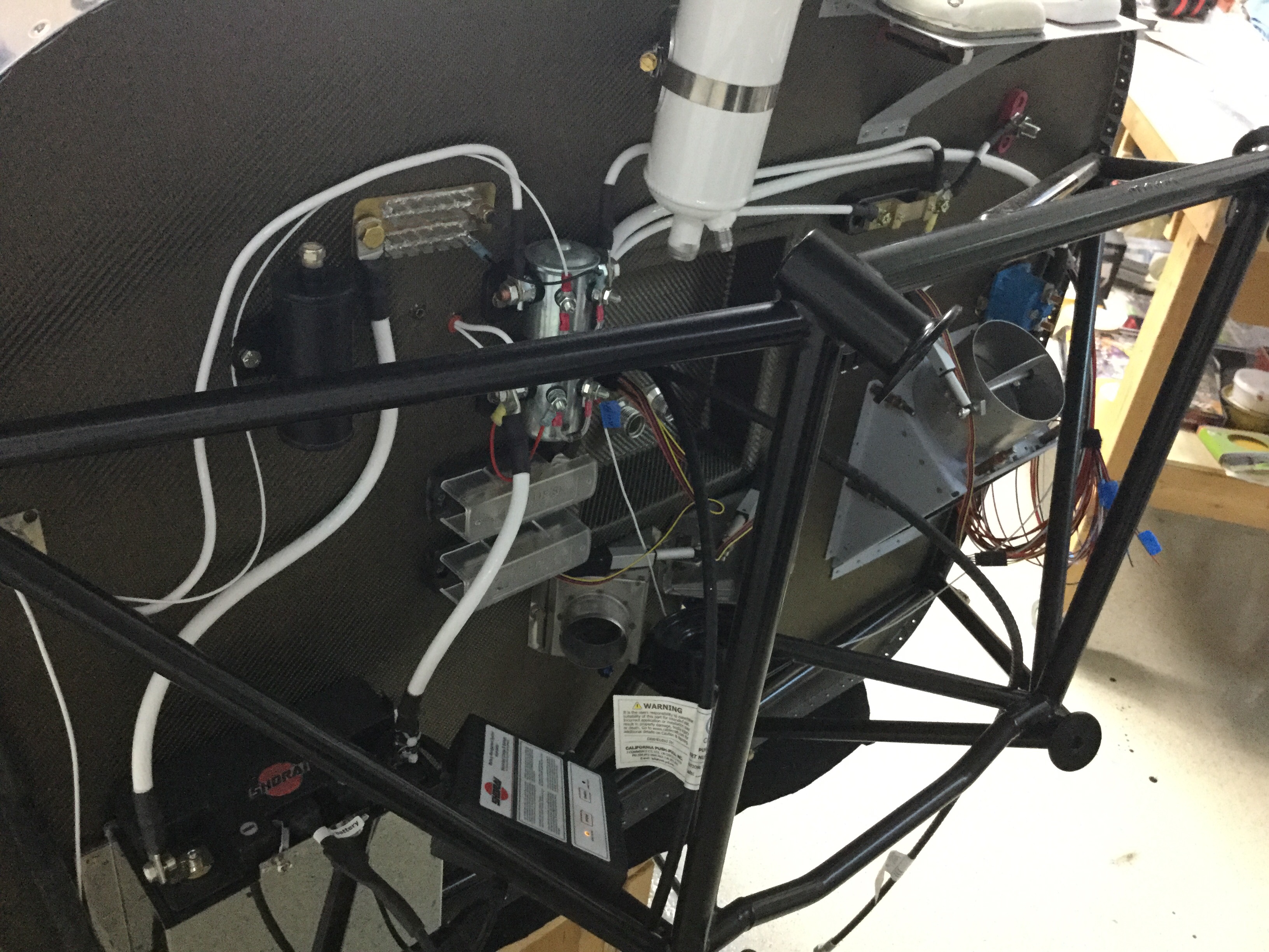
The big wires were taking up a lot of room on the shelf and with the components on the firewall all mounted, I could get the thick stuff installed.  I took some time to determine what size lug would be needed at each end of wire and ordered all the supplies in.  Great move because I had all I needed plus a few spares of everything.  The crimper I bought from Amazon worked well and it was a pretty easy, fun job overall.  It helps me visualize the power system now even better and I’m happy to say that I feel safe and secure with the architecture providing power for the plane.
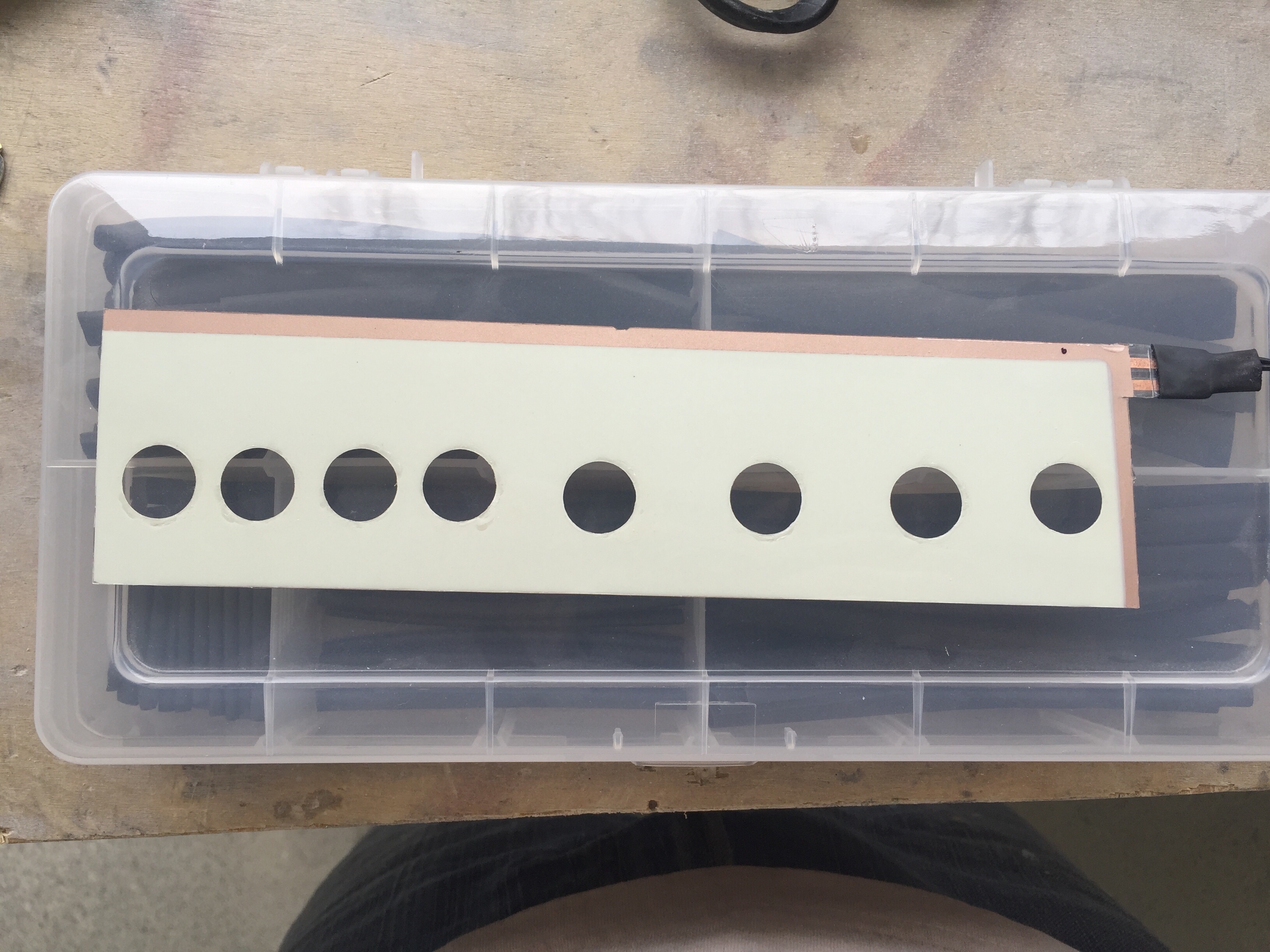
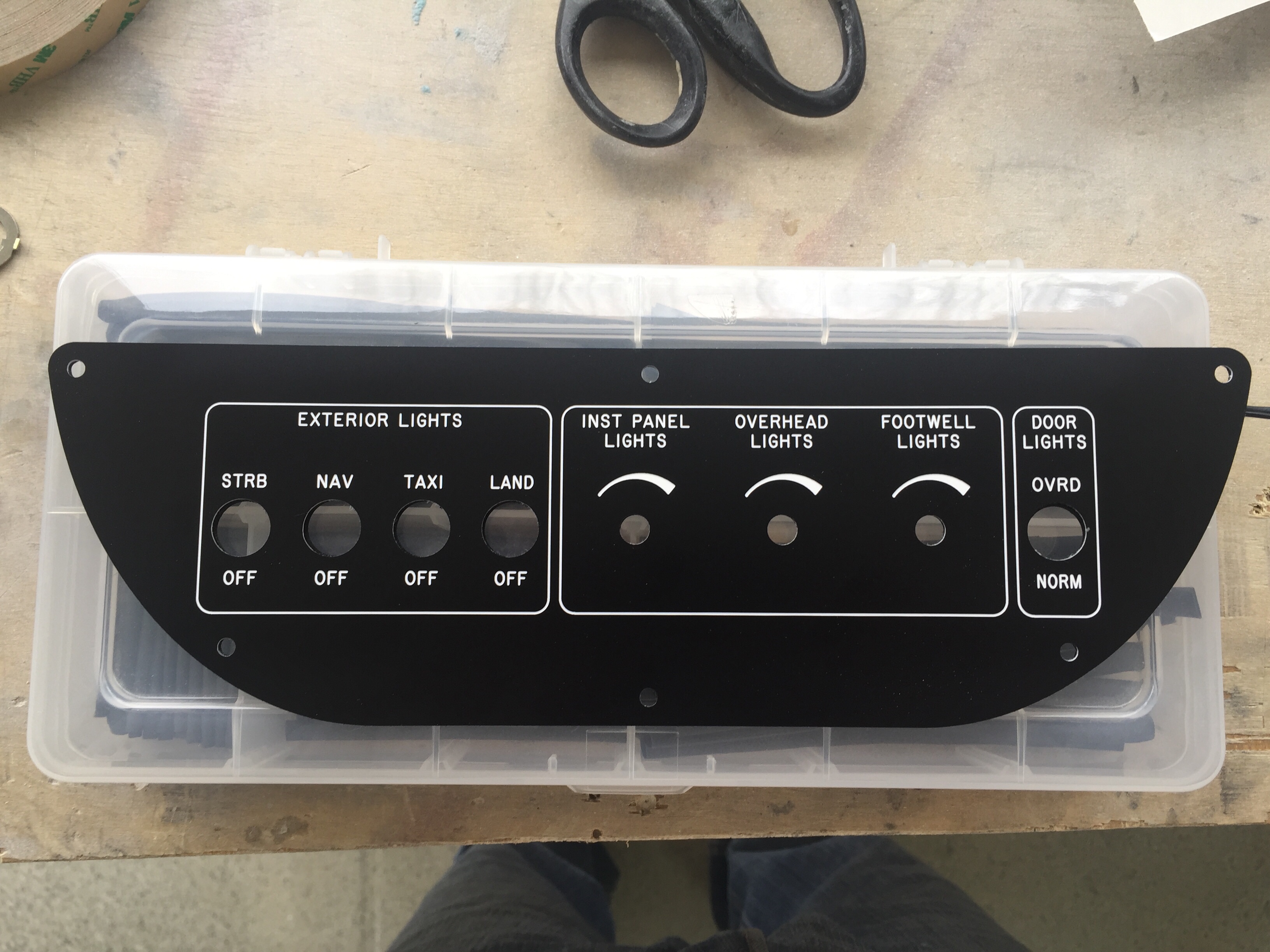
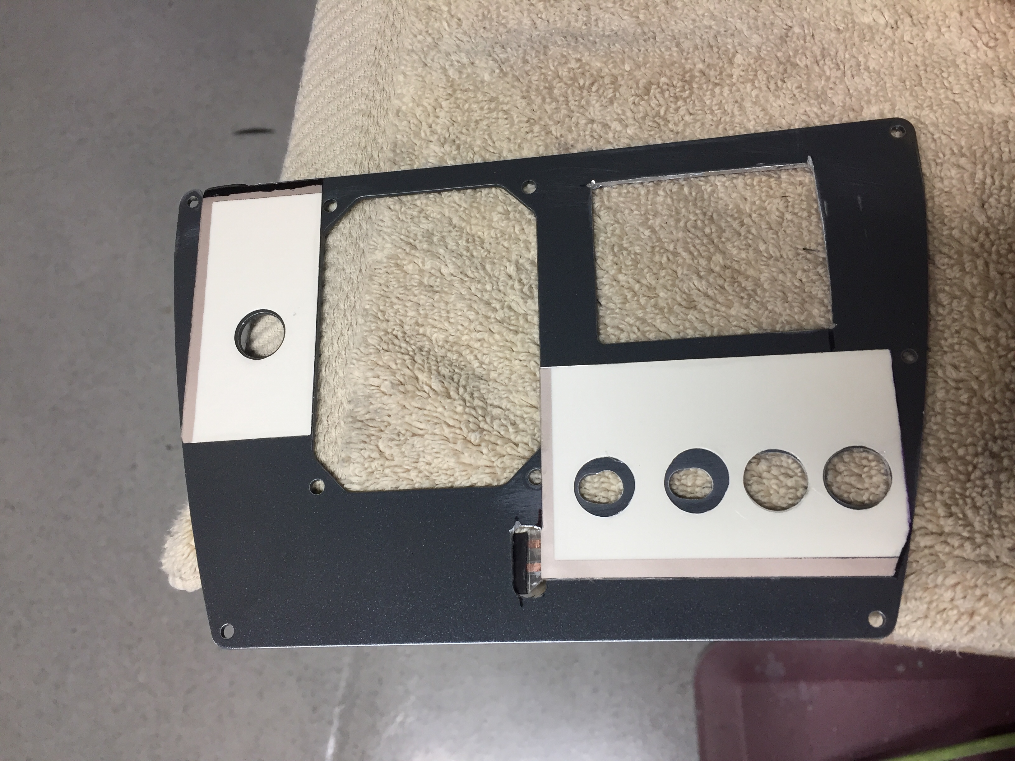
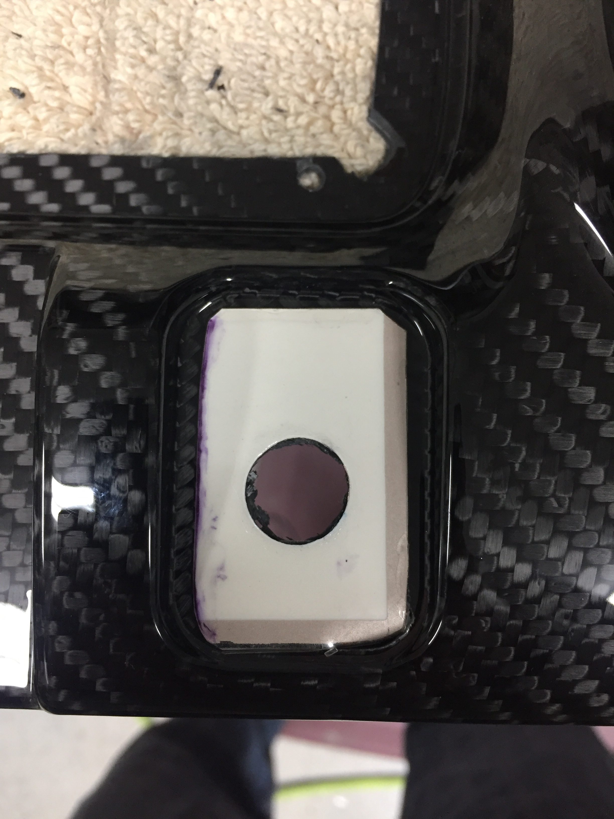
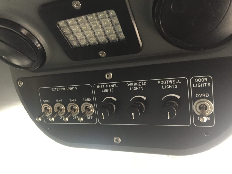
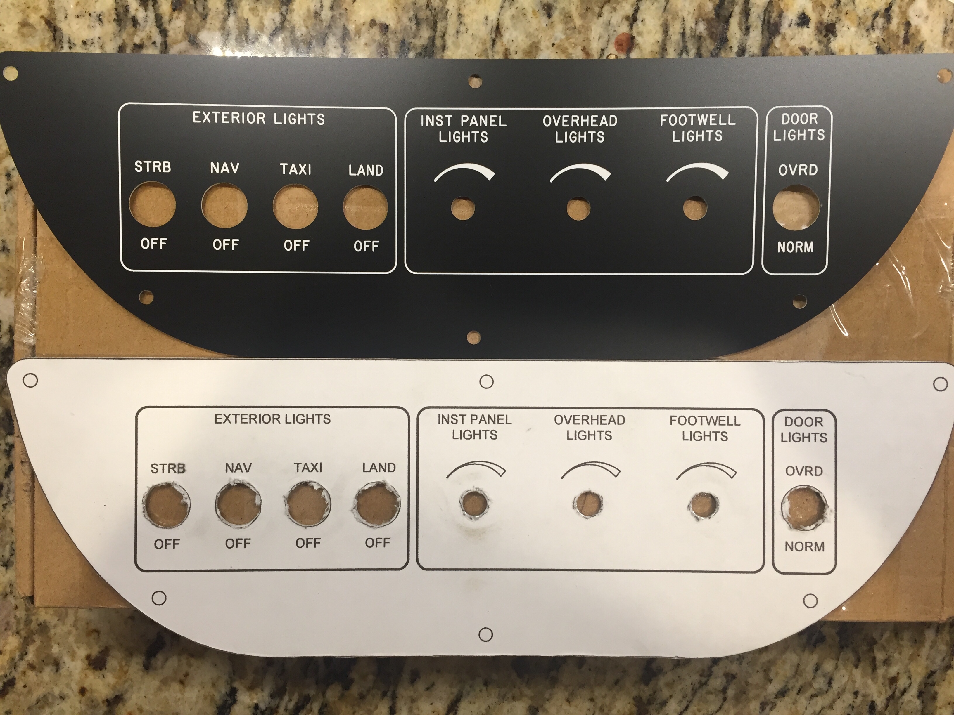
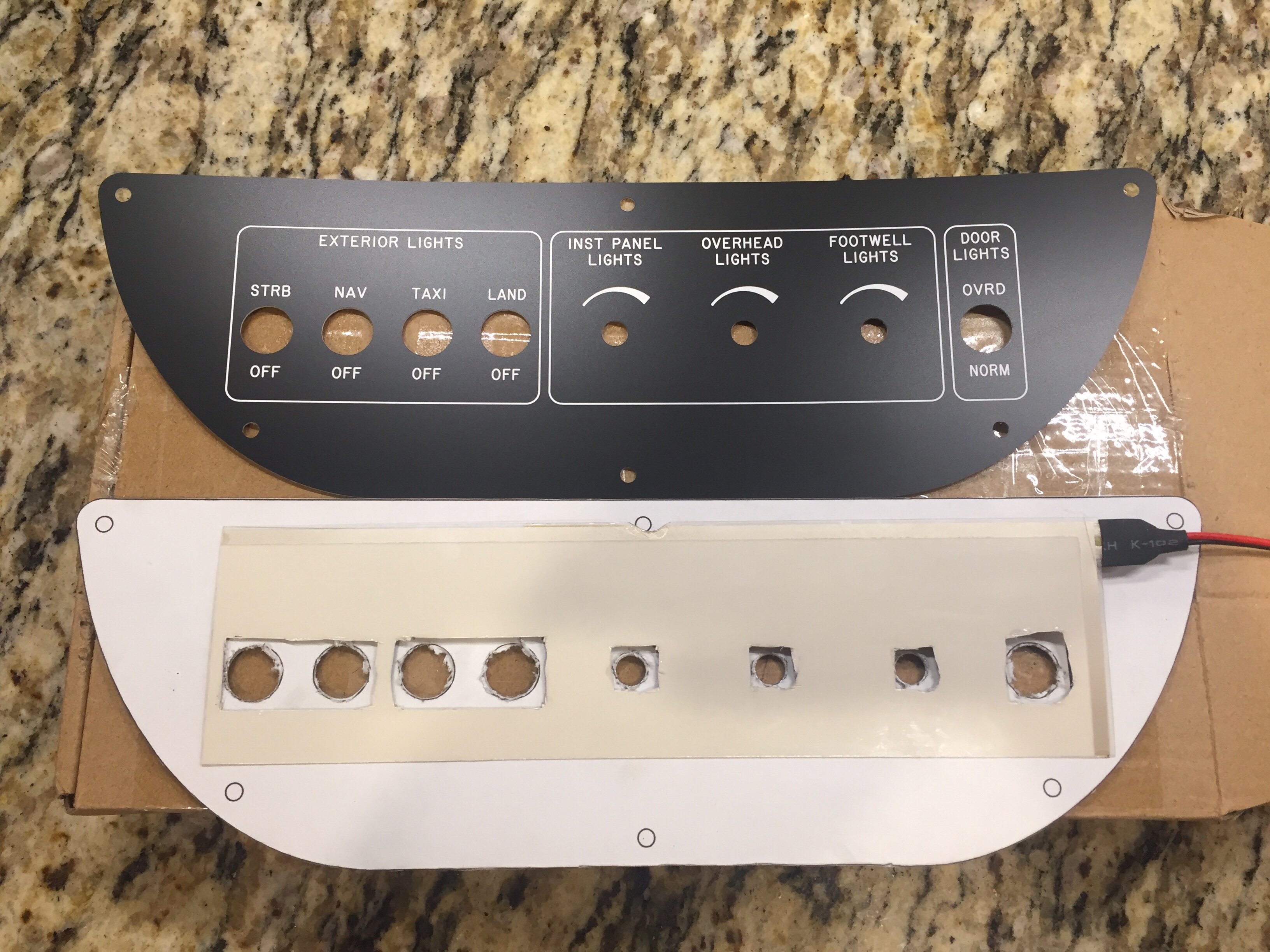
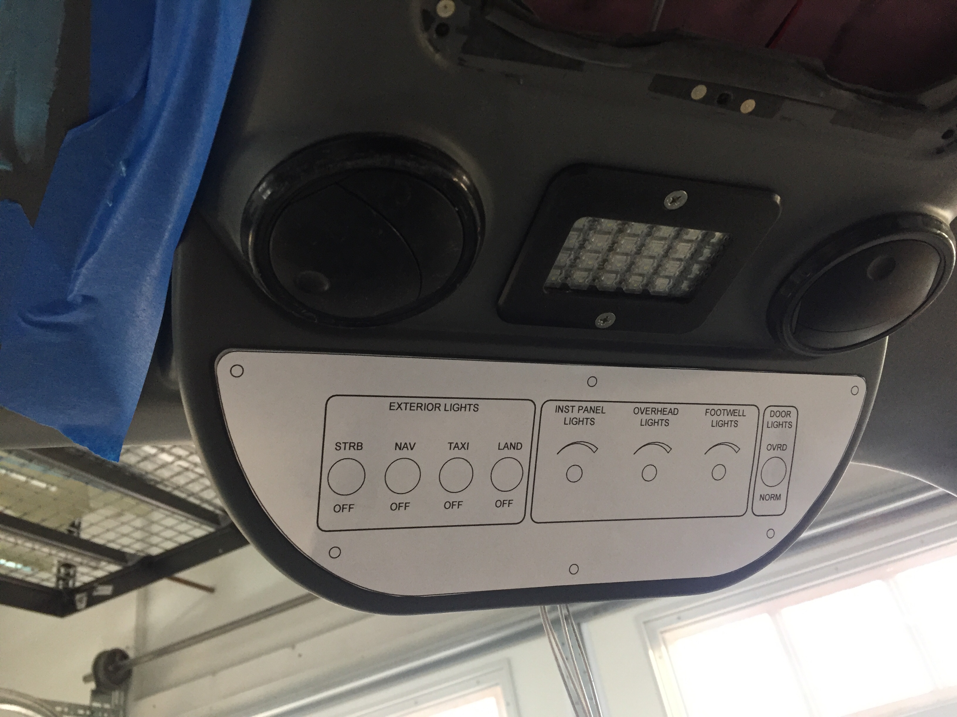
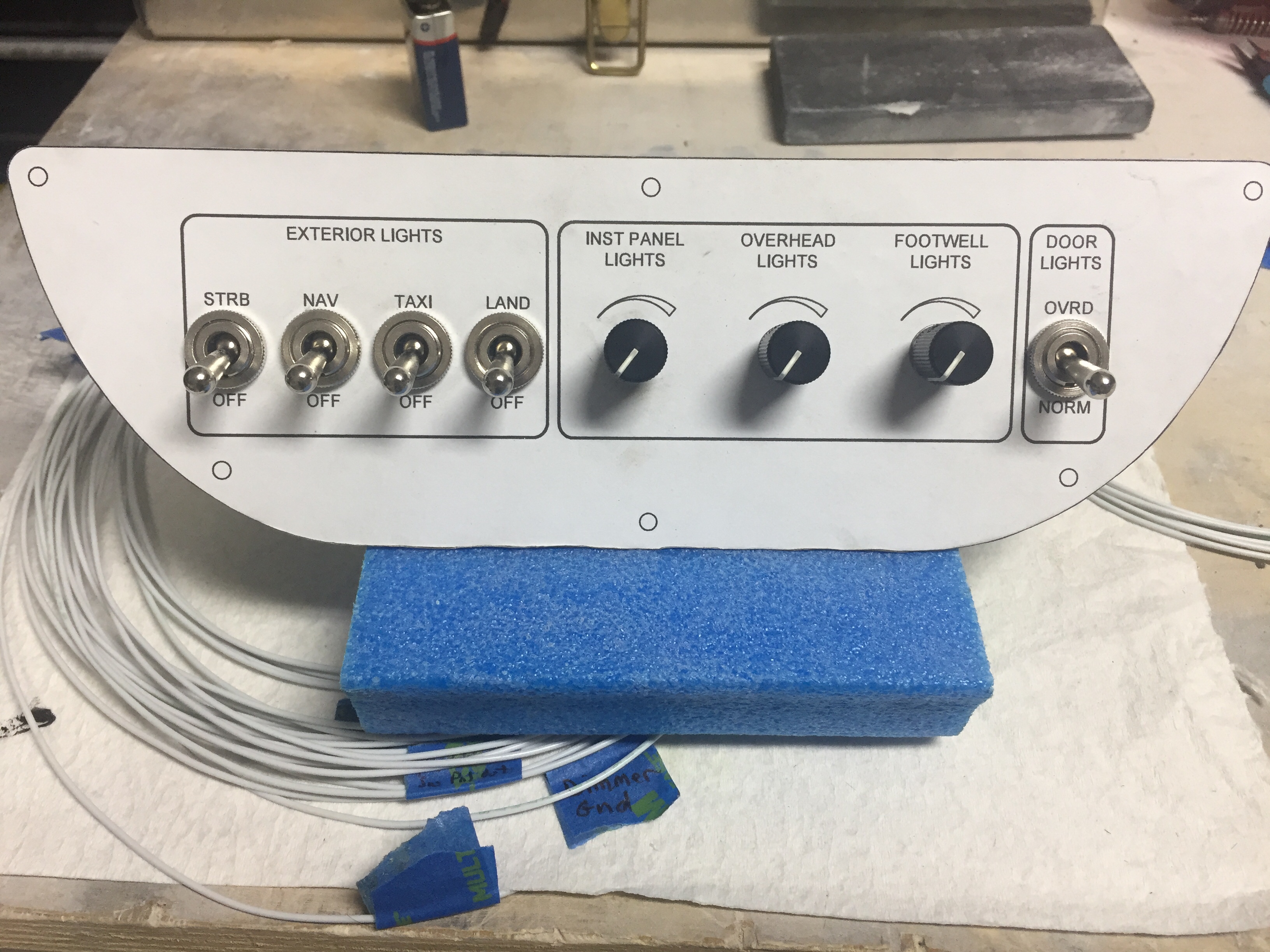
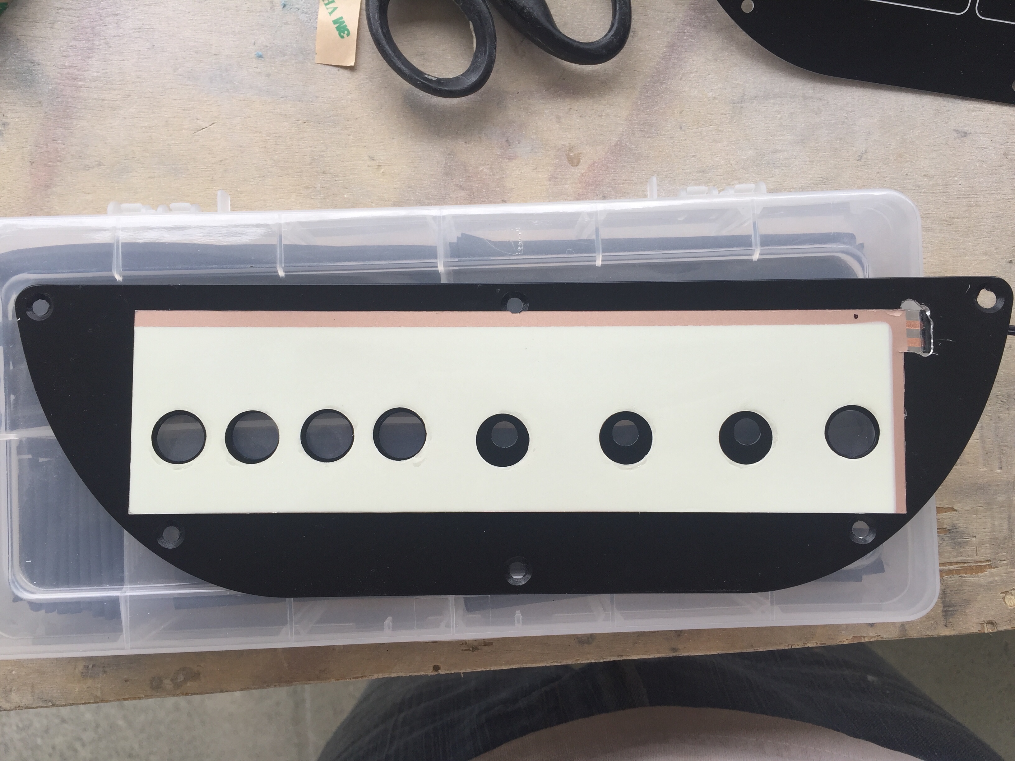
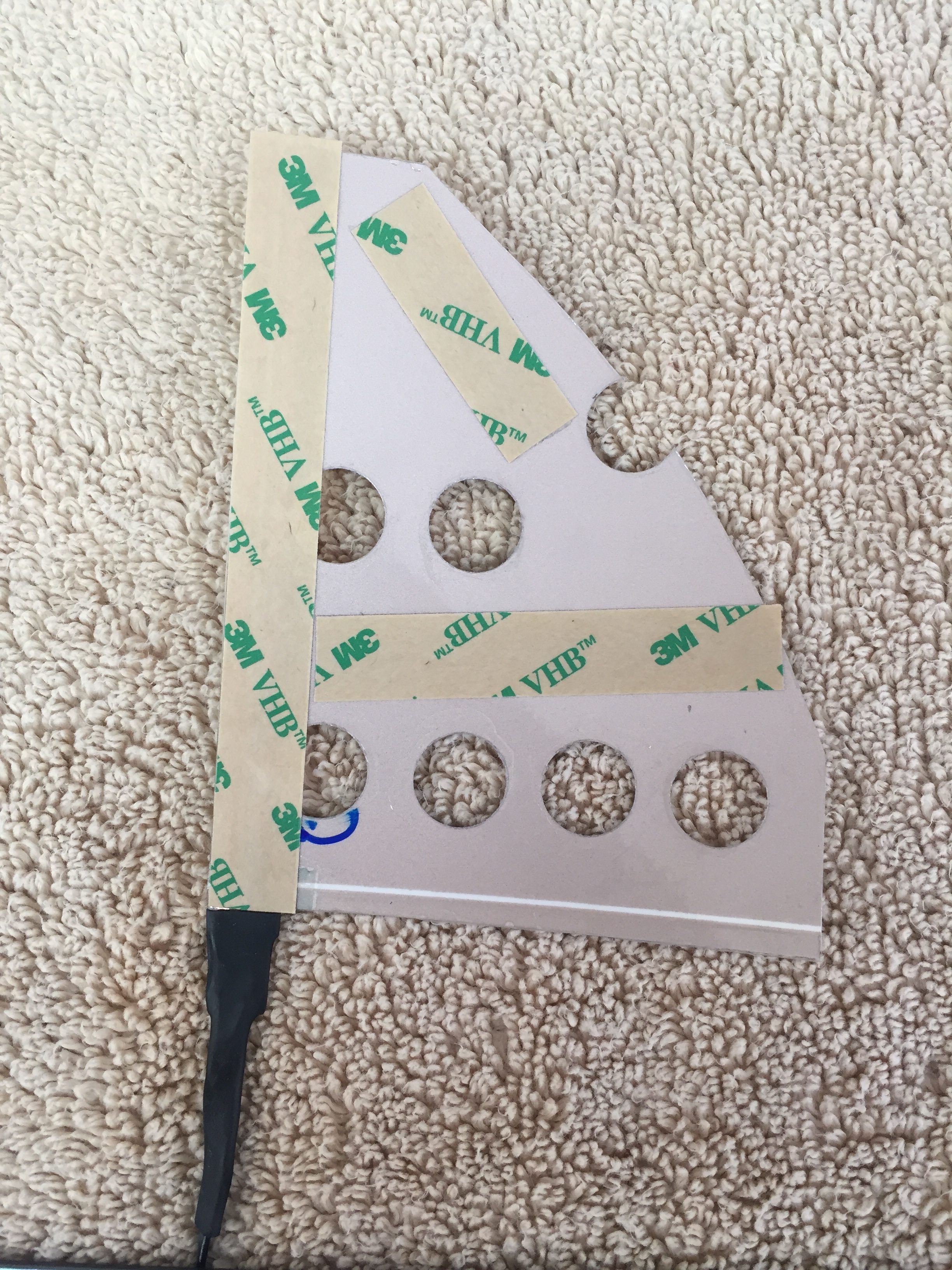
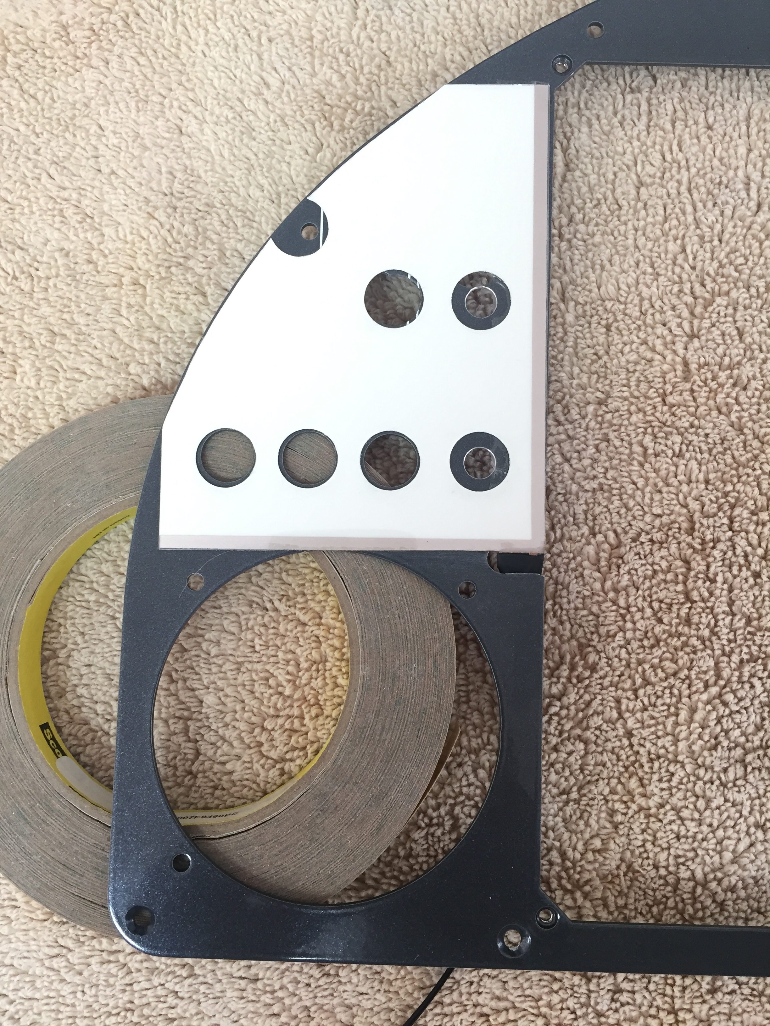
After receiving the newly etched panel, I could fabricate the last of the switch panels so the avionics would be ready for final install.  Just like all the others, I started with a printed 1:1 image of the panel I had designed spray glued onto the aluminum sheet.  I cut that out then final trimmed it using the acrylic overlay before painting it black.  The back light panel is placed on the aluminum panel and positioned using the overlay to get it just right before trimming for the switch and USB ports.  This one was pretty easy with large cut outs.  I use 3M double sided tape to secure the back light panel then lay the adhesive backed overlay on top to finish it all out.  I use a Sharpie to color the white on the edges of the overlay to help control bleeding from the back light and give it a nice finished look.  I did have a little trouble with the wires on this panel and wound up replacing it all together with 22 AWG Tefzel soldered on the panel itself.  I wish I had done that with all the others, as the wire used from the panel is crappy and hard to terminate using the micro-molex connectors.  It turned out great, though, and is the last piece of the instrument panel.
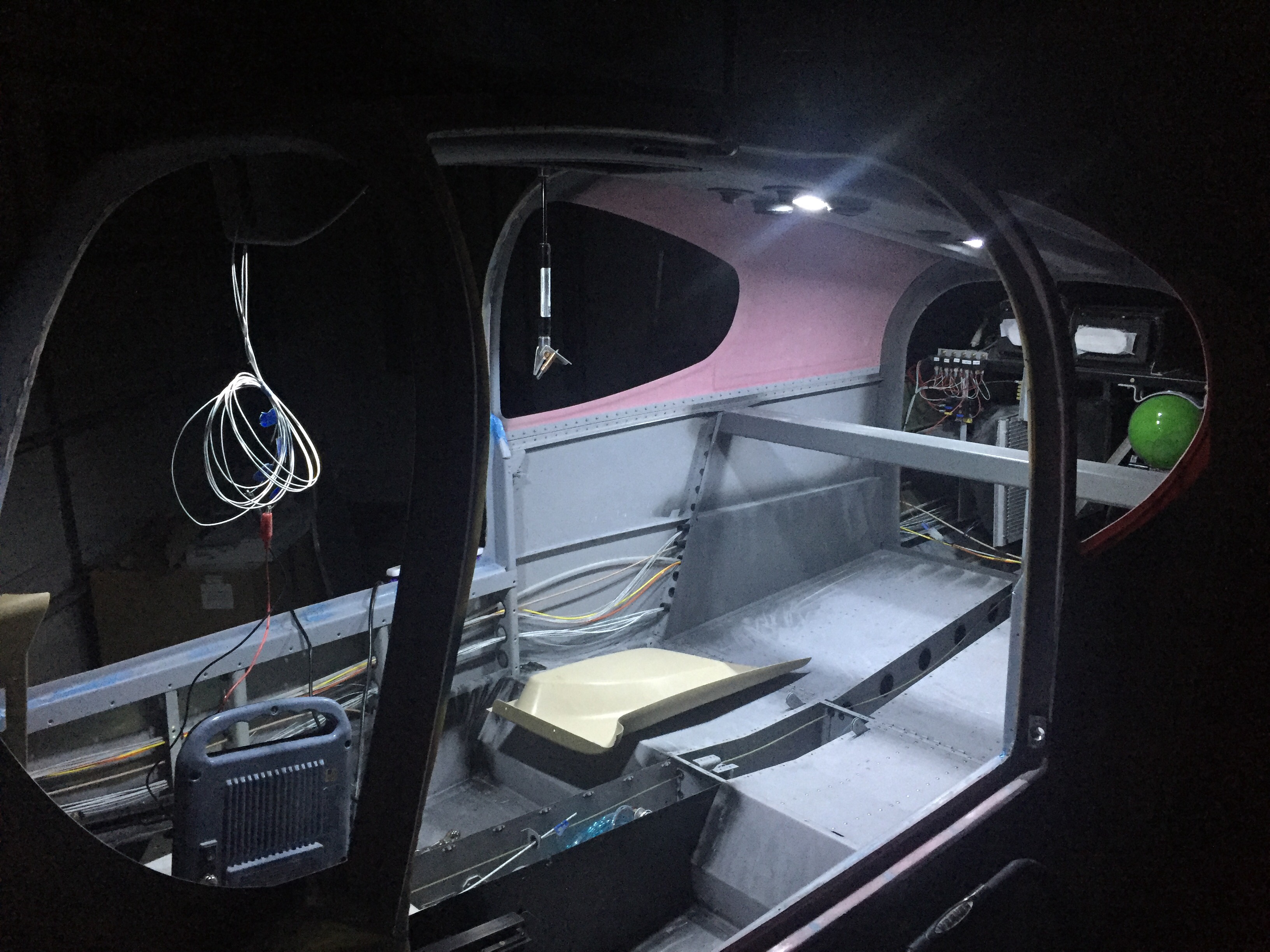
Finally, I worked up two brackets for the micro switches on the doors and wired those along with the one on the baggage door for the lighting control module.  I also used the micro switch on the baggage door as the safety switch input for the EFIS annunciation.  More wires to run, oh boy.  A pretty quick job that should work just fine.  I did have to run an additional wire up to the overhead as I had picked up power and ground for the door lights from the overhead lights and that’s not how the lighting control module is set up.

While my plane does have a lot of wiring, it’s nothing compared to the big boys at work.  This shot is behind the port side avionics bay in the C-17.  Now that is a lot of wires!
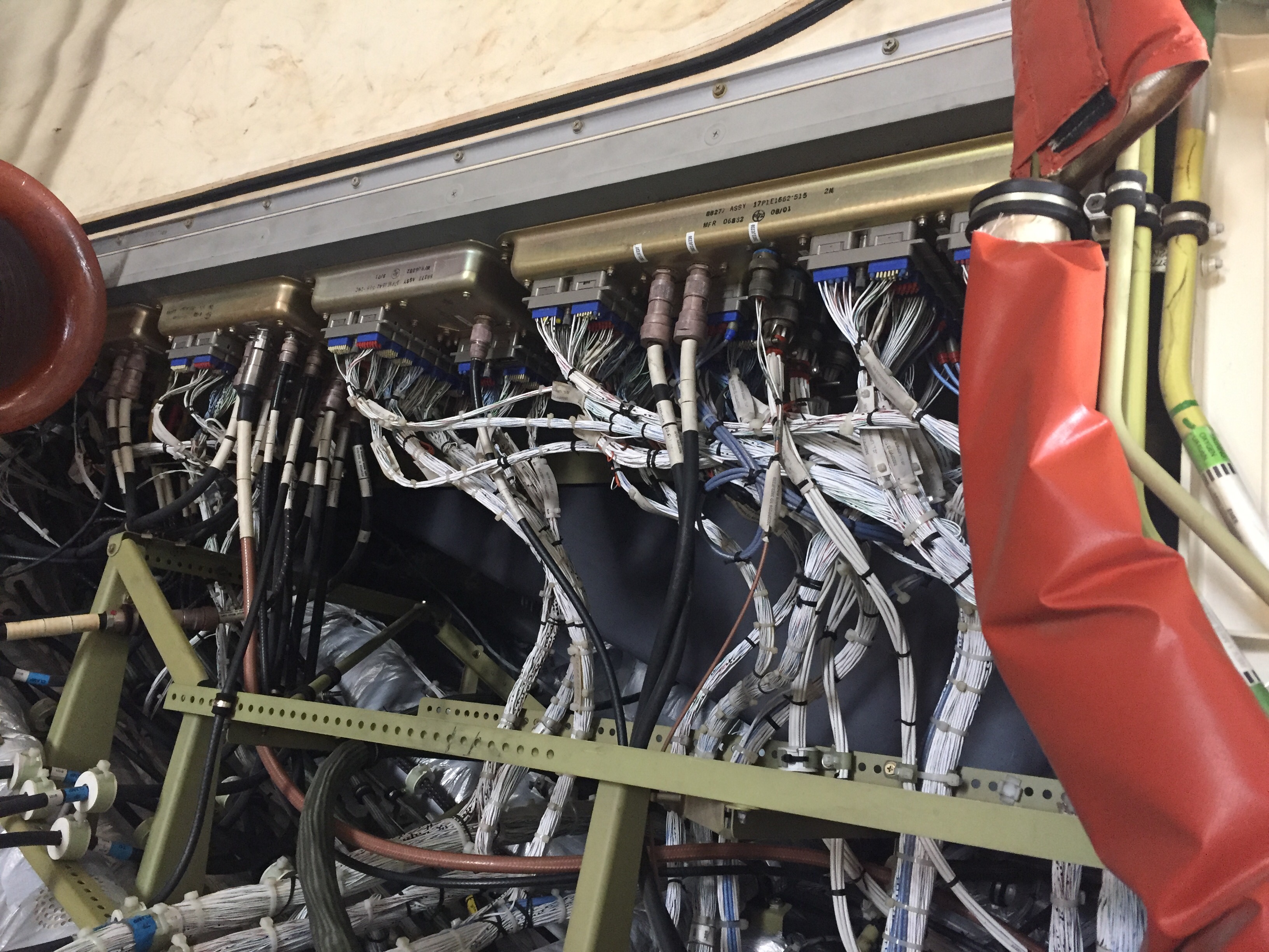
Light at the end of the tunnel

I have rearranged just a few items on the firewall and after getting confidence in drilling several holes, nothing was stopping me from drilling the remaining locations.  The toughest was the large hole for my insulated pass through for the main power wire.  I made the mistake of using a unibit and it really made a mess of the job.  In the end, it turned out okay, but I used that as a lesson to chain drill all future large holes in stainless with a #40 bit.  I needed to get the nutplates installed and all components temp mounted to ensure a proper layout so I could move on with the firewall insulation.

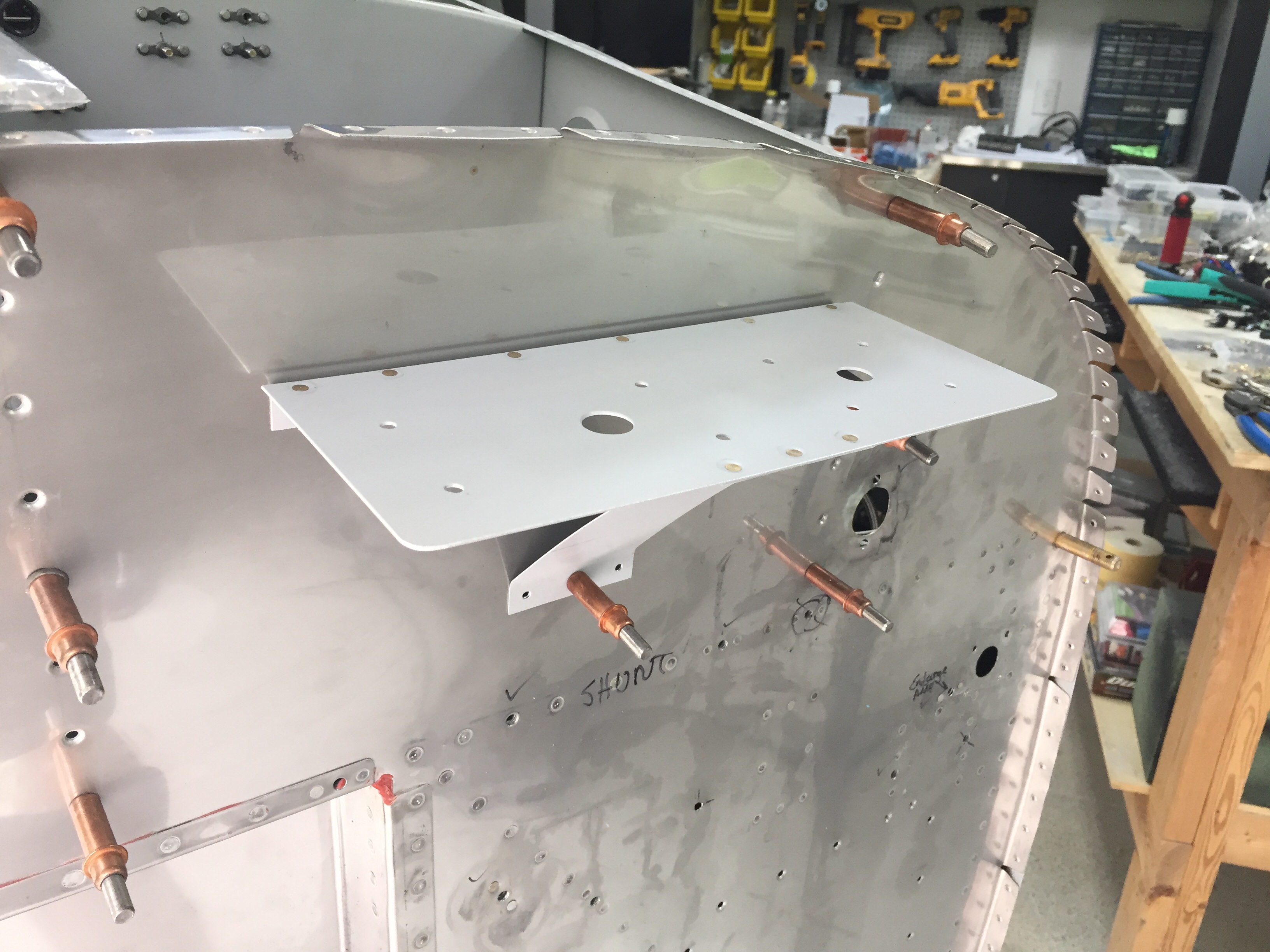
My two GPS antennas will be firewall forward just below the cowling as others have done, so I built a shelf for the AFS and IFD antennae.  The cables and wires will go through a dedicated pass through just below the shelf.   I ordered and will be using high-temp silicone grommets from ACS for these and the control cables going through the firewall.  They will be sealed with Firestop per the plans.

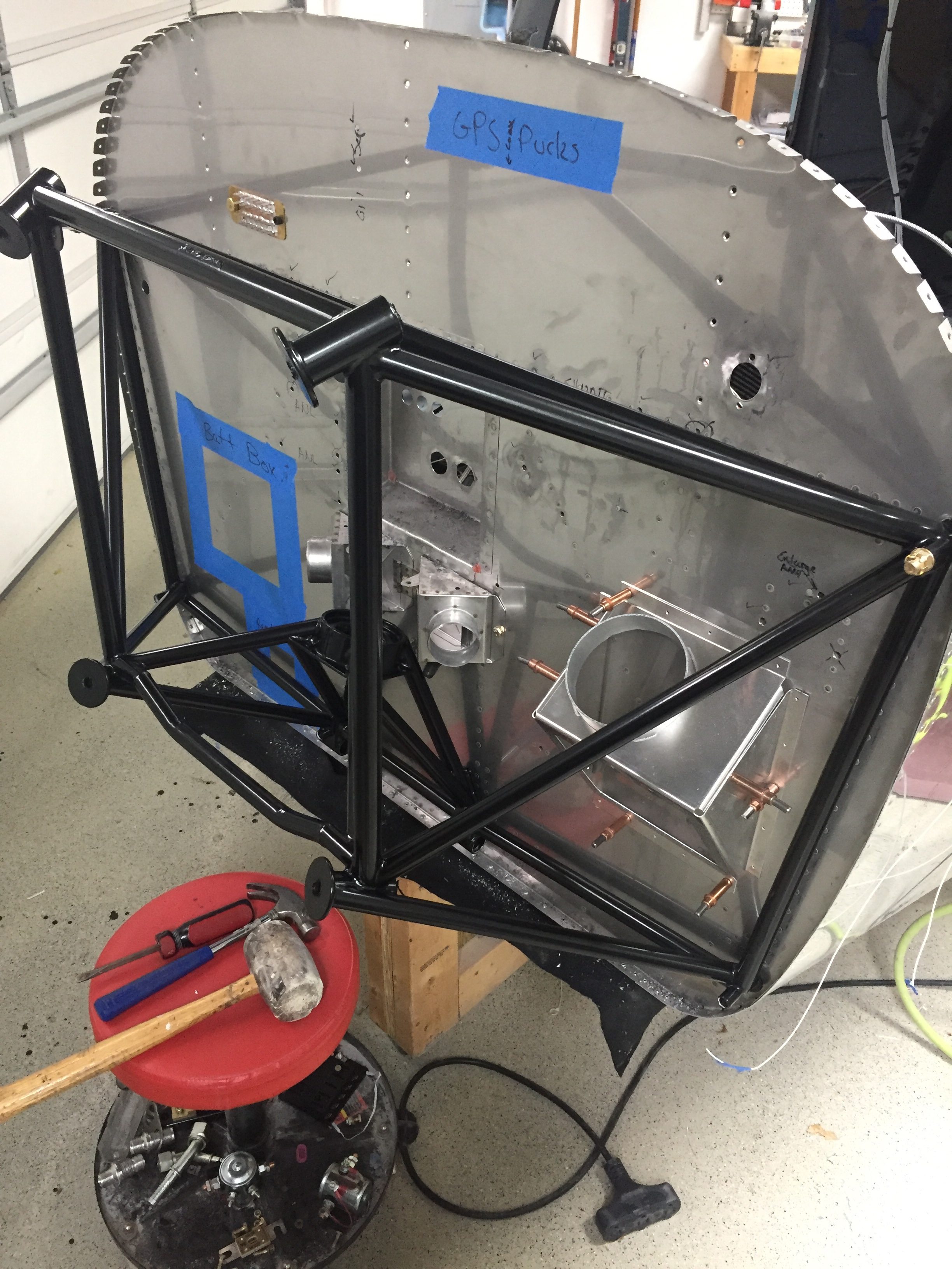
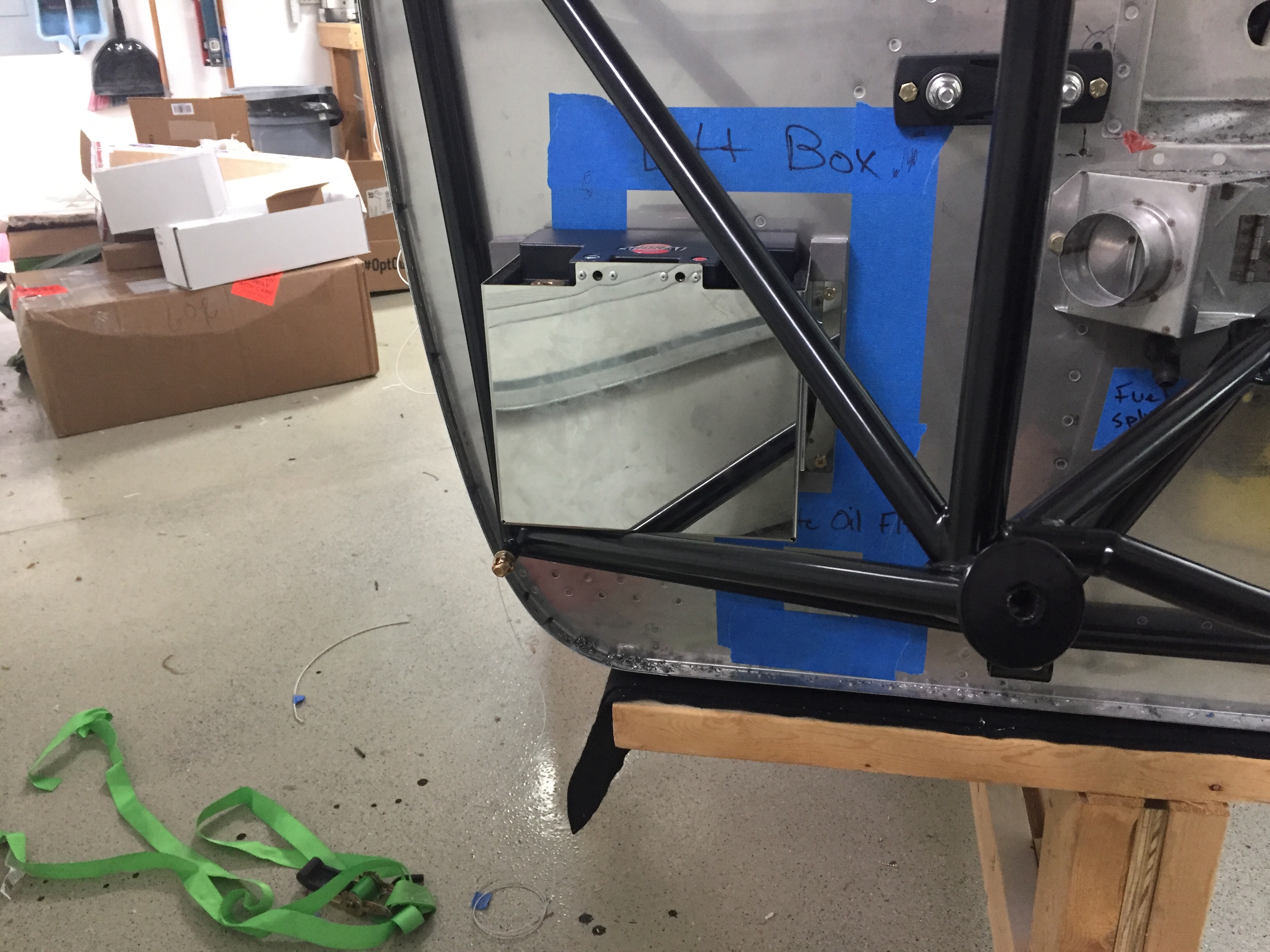
I decided to have the engine mount powder coated black just for a little extra pop and get rid of the white.  It came out nicely and I went ahead and drilled the holes to get it ready to mount.  I didn’t have to do too much finessing to get the holes lined up and it proved to be a quick job.  That also allowed me to position the battery box and ensure clearance for the battery to come out without having to remove the box from the firewall, again thinking about maintenance down the road.  The box is insulated and made by EarthX but is about a 1/4″ too shallow for the Shorai battery.  I used some spacers and high temp foam to stand it off from the firewall and allow just enough room for a snug fit.  The retainer of the box has a bracket to mount a 1″ blast tube which will come from the rear baffles for battery cooling.

The Shorai battery was a last minute decision over the EarthX for a few reasons.  I spoke to a few other 10 flyers who have had EarthX failures and while the service to get them replaced was excellent, no root cause could be found.  Further more, the batteries have the internal BMS which will protect the battery’s voltage from dropping too low.  There are a bunch of pros and cons that I won’t get into about BMS but I decided I’d rather kill a battery than killing myself because my electrically dependent engine quite to preserve a $300 battery.  The Shorai also has a higher aH rating, at 36 meaning in theory I’ll get more power for longer than the EarthX.  It does not have an internal BMS so will die giving it’s last bit of power to me, which is what I want if both of my alternators fail and I need to keep flying.  It’s about the same size, the same weight, and cheaper to boot!

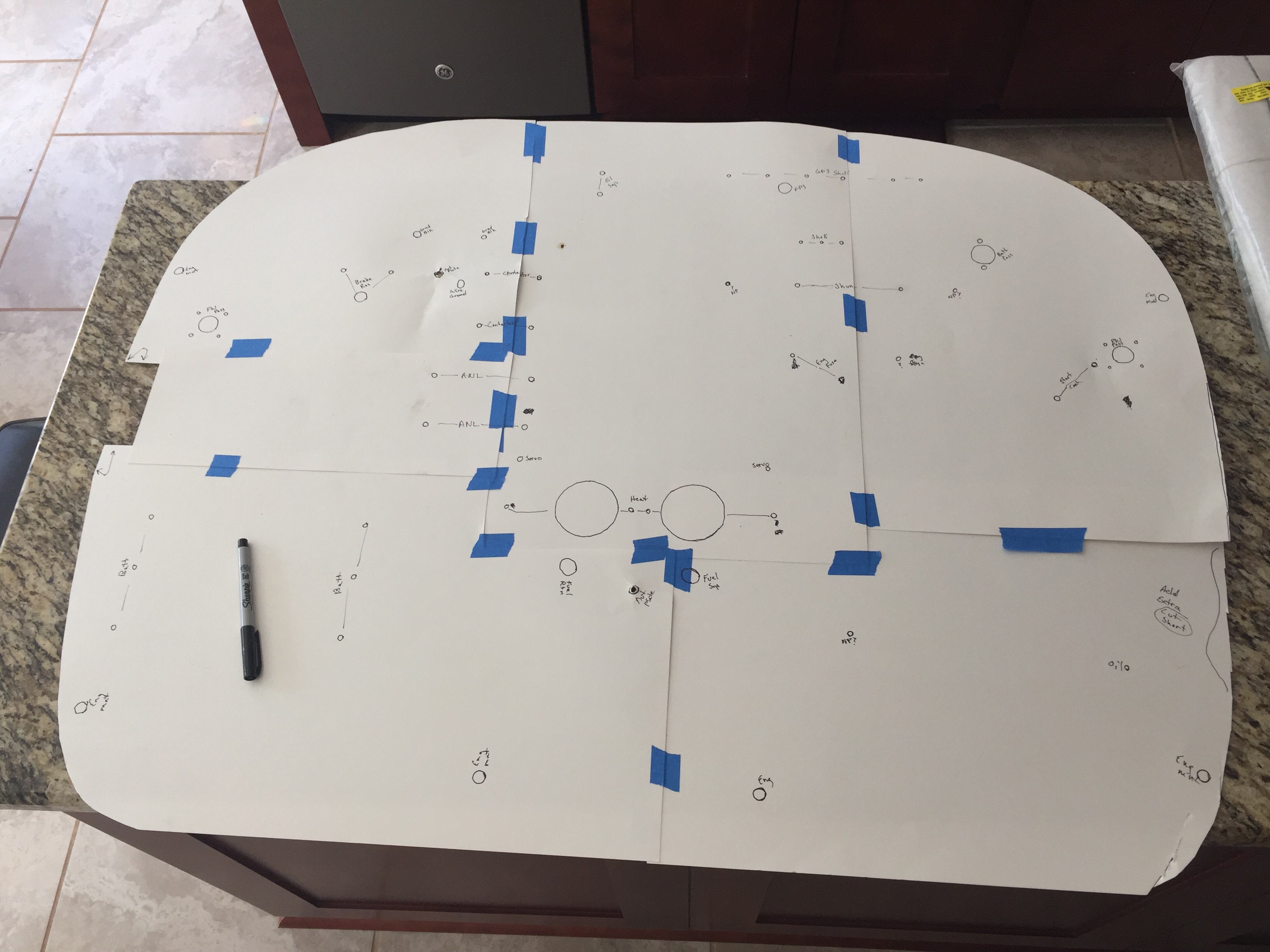
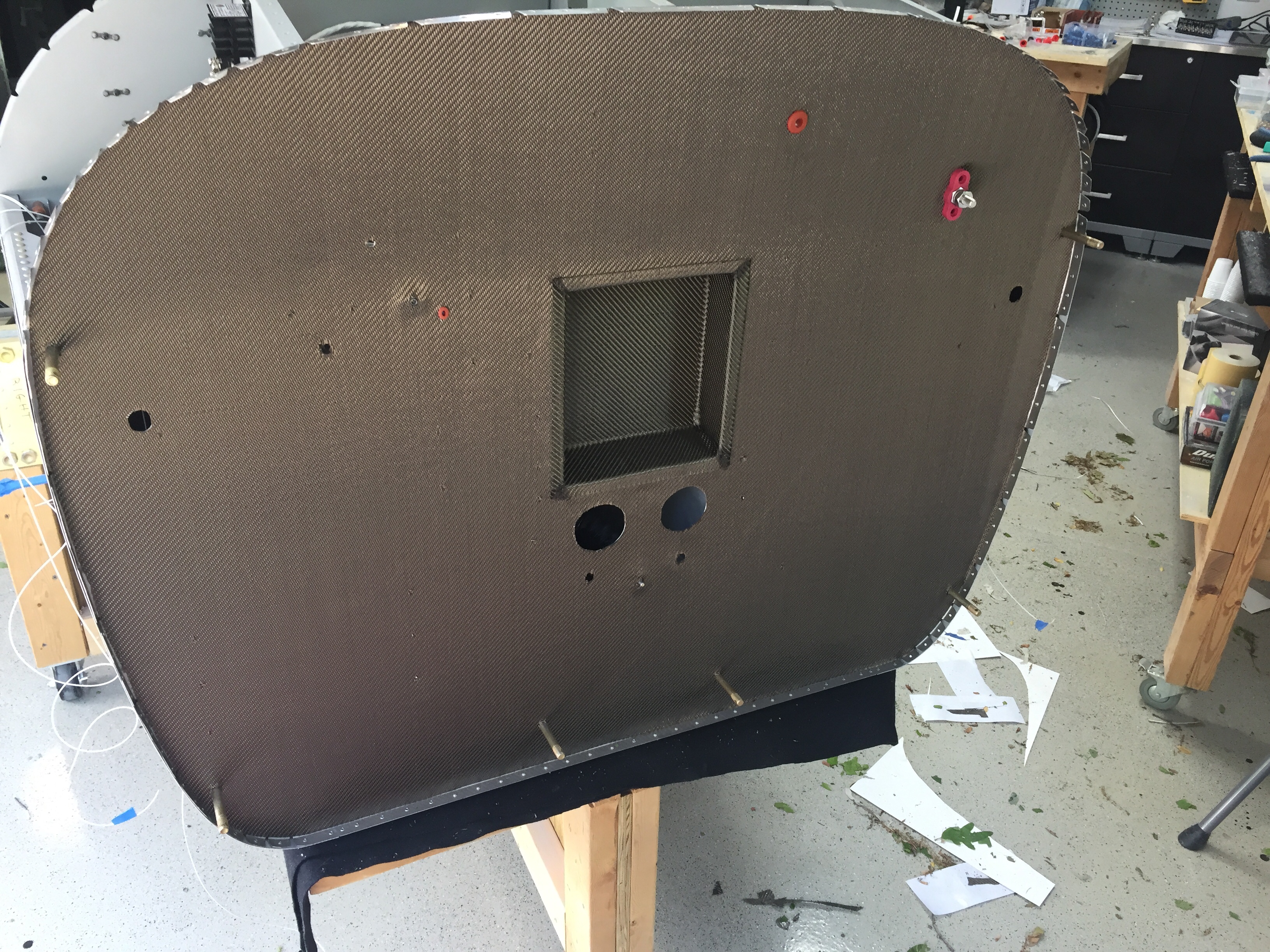
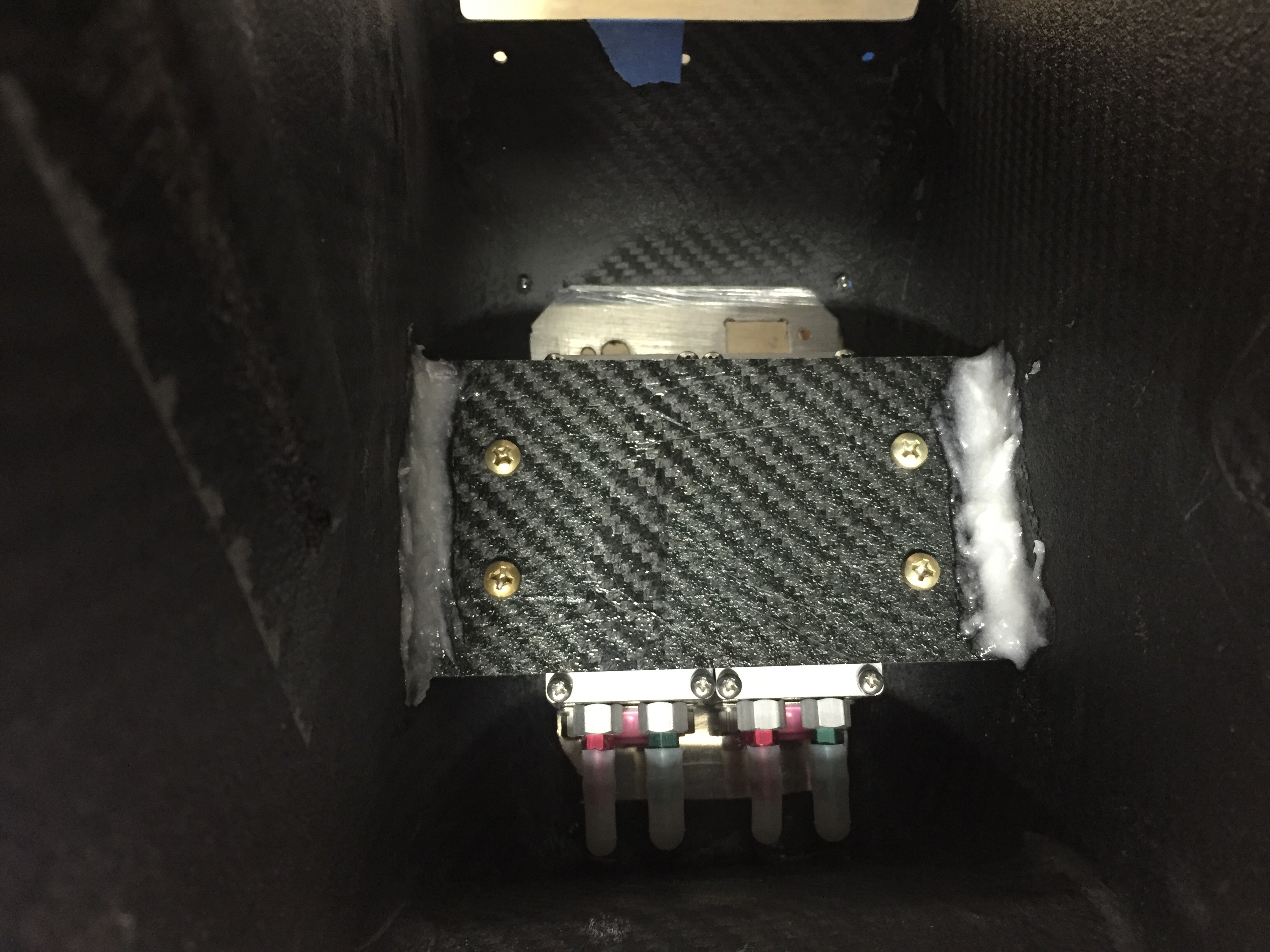
Once everything was drilled and nutplates installed where needed, I made a template of the firewall and holes on poster board to transfer over to the lava shield insulation mat.  I got the product referral from John Walker and have seen his up close really looking and performing well.  Plus, it’s a lot easier to install and work with than the fiberfrax sandwich, in my opinion.  The lava shield is a carbon fiber material with a self adhesive backing.  I trimmed most cutouts with a razor and decided to just match drill the small rivet and bolt holes once it was on the firewall.  It was pretty easy to apply the mat to the firewall, taking my time and treating it like a big sticker.

I cut out the area covering the recess and used scrap material to fill in the edges of the recess.  I chose to glue the edges, as the material is a bit stiff and didn’t like the sharp outside radii.  I’m really happy with the finished result, not only aesthetically, but functionally.  It should provide a nice barrier for heat transferring to the cabin and gives the firewall a nice finished uniform look.

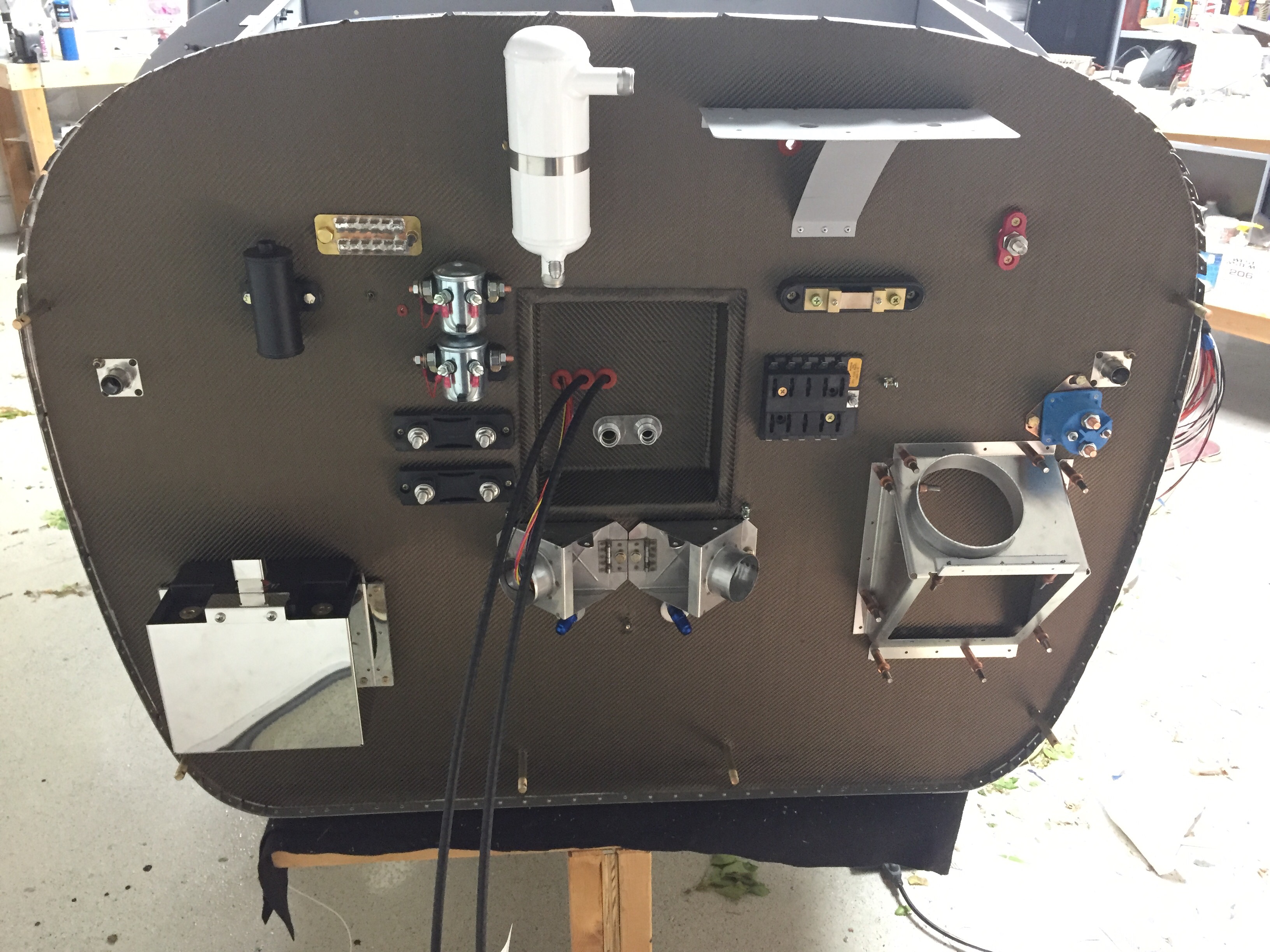
It was finally time to bolt all the stuff to the firewall and get my workbench cleaned off.  Again, having the forward fuselage section removable at this point really made the job easy as I could just reach around and secure nuts, etc. on the cabin side of the firewall.  I used nutplates on everything that would have a good chance of needing removal but used nuts on the few items that would only come off once or twice in the plane’s lifetime or could be serviced while installed.  It’s pretty cool to step back and look at all the components up there and seeing how it’s all going to fit together.

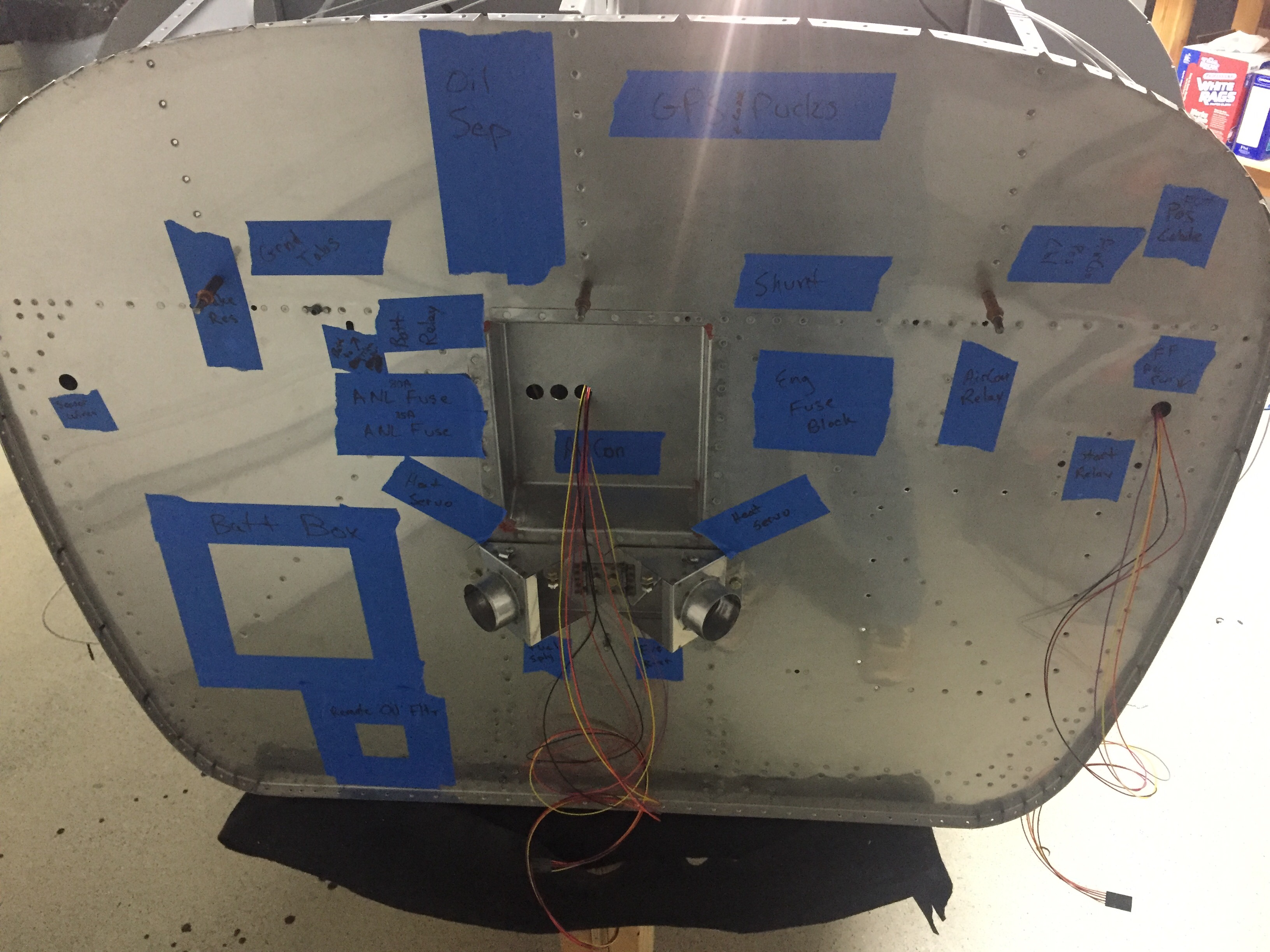
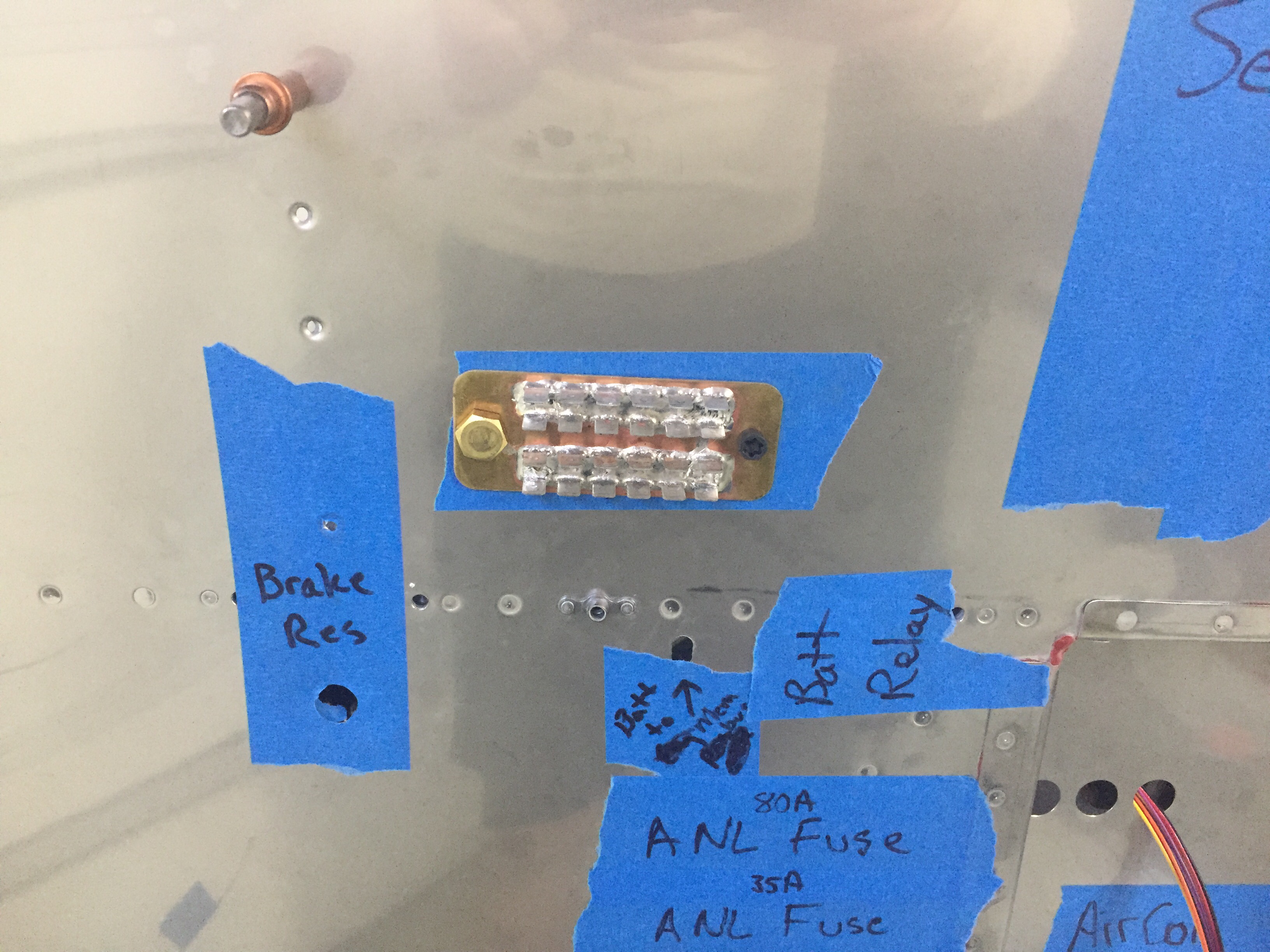
I am pretty confident the locations will allow clearance with the engine except the oil separator.  I’m afraid it’s going to hit my stand by alternator, but only time will tell as the measurements I’m getting from others is a bit misleading.  We’ll see and if need be, it’s a easy fix.  I have the main power pass through on the upper right, a 3/4″ pass through on the left and right side, grounding tab and main grounding bolt on the upper left, and GPS shelf on the upper right.  The two contactors on the left side are GPU (on top) and batt master on the bottom.  Two ANL fuse blocks are below those, one for each alternator.  The prop and throttle cable (no mixture with SDS) come from the center and I’m using the third hole for the heat vent servo wires.  On the right, the AFS shunt will measure alternator current going into the system and the starter contactor is at the stock location.  The fuse block is for all of the engine components related to SDS including coils, ECUs, fuel pumps, etc.  Finally, the oil cooler has been modified to fit the larger 2007X oil cooler and will have a damper controlled by a TCW servo just like the heat vents.

Lot’s of progress that is really rewarding as I’m slowly emptying all the boxes and cabinet shelves holding purchase but uninstalled items!  Next up will be attacking the throttle and center console along with the rest of the instrument panel and putting the forward fuse section on for good.

Feeling wired

Have I mentioned there are a lot of wires in my plane?  Well, there are.  Compared to others, I’m on par or above average on the amount of wires.  I know my amount is a bit higher due to the aircon and using a single ground location, eliminating local air frame grounding.  I chose to do this to avoid noise (hopefully) and chasing grounds around.  Wire is cheap and relatively light (I’m not pinching pounds here) so why not?  I also have a lot of interior and exterior lighting which adds more runs.

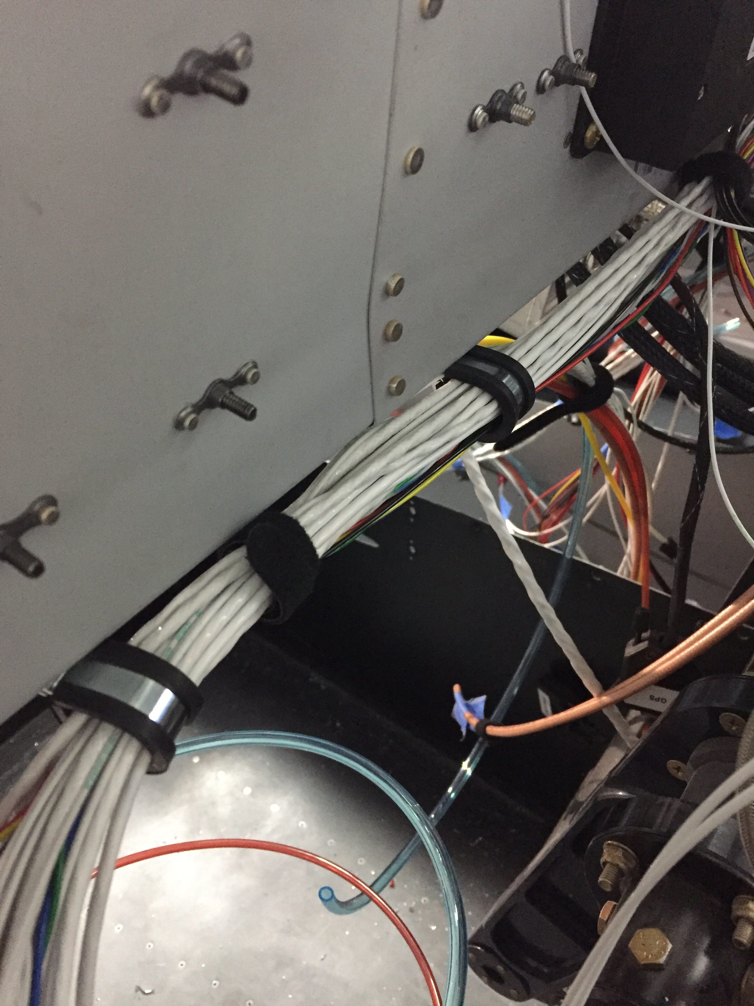
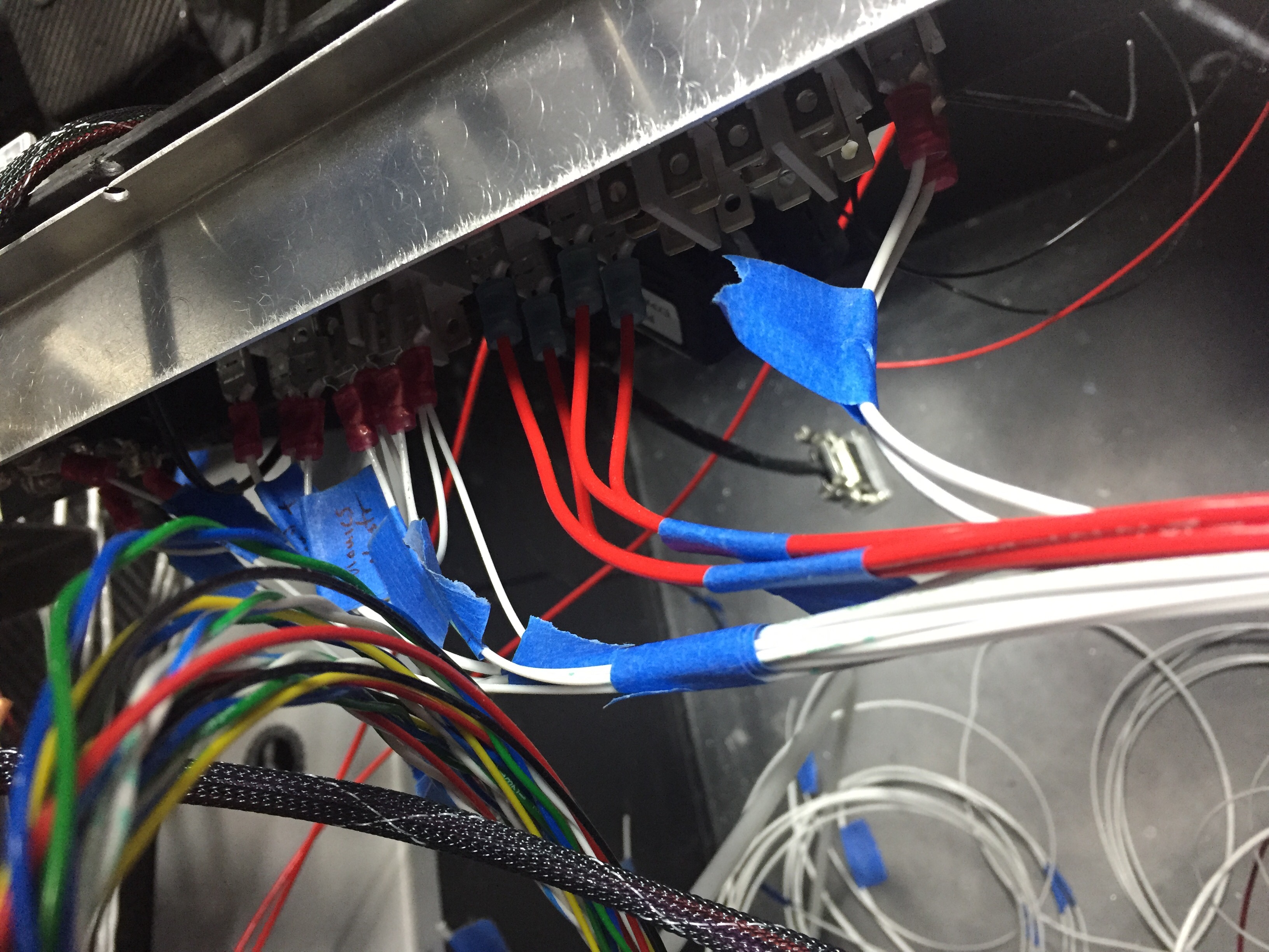
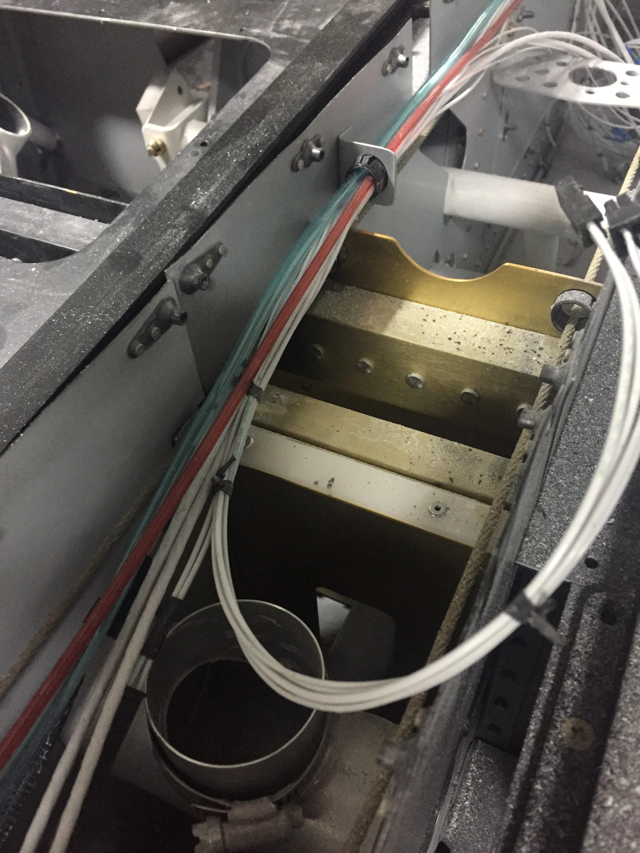
Throughout all of my work on this, I’m attempting to stay neat and organized.  At least in the plane, if not the shop and workbenches.  I got some cheap Velcro wire wraps from Amazon to help bundle wires as I went.  It also helped me created bundles and locate clamps that will need to be installed.  I’m running the majority of wire together along the bottom flange of the subpanel.  Some folks try to separate a lot of different things depending on current/signal/etc. but I’ve seen a lot of professionals put everything in one giant bundle including some big names in the avionics world.  I did keep the coax in its own bundle as much as possible and am trying to keep the thick wire away from other smaller wires.

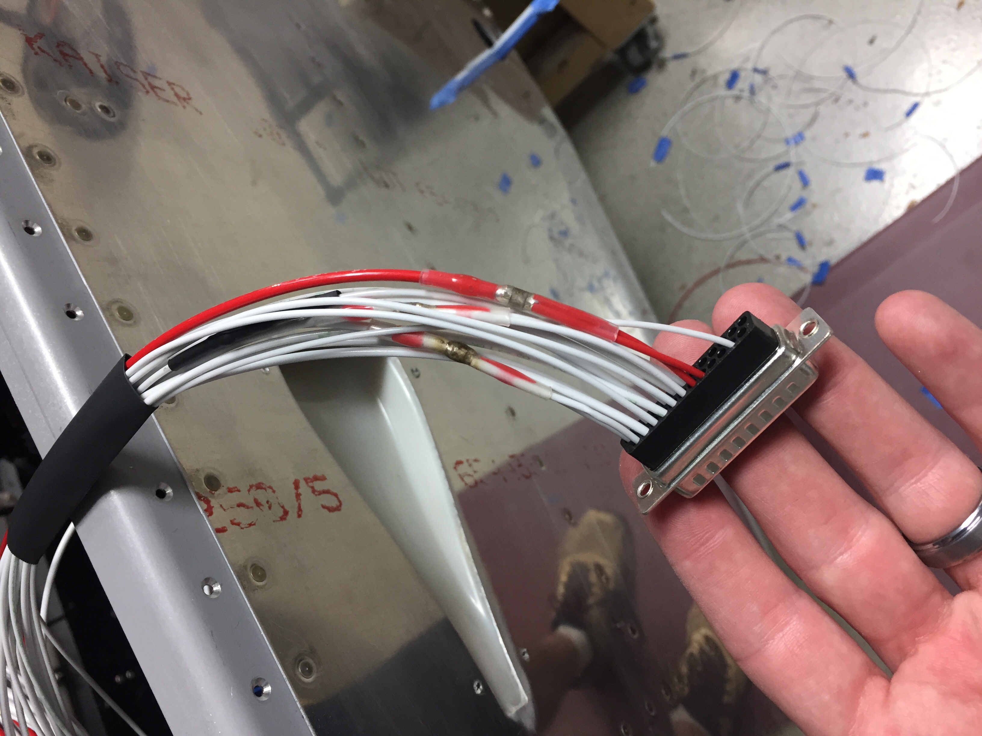
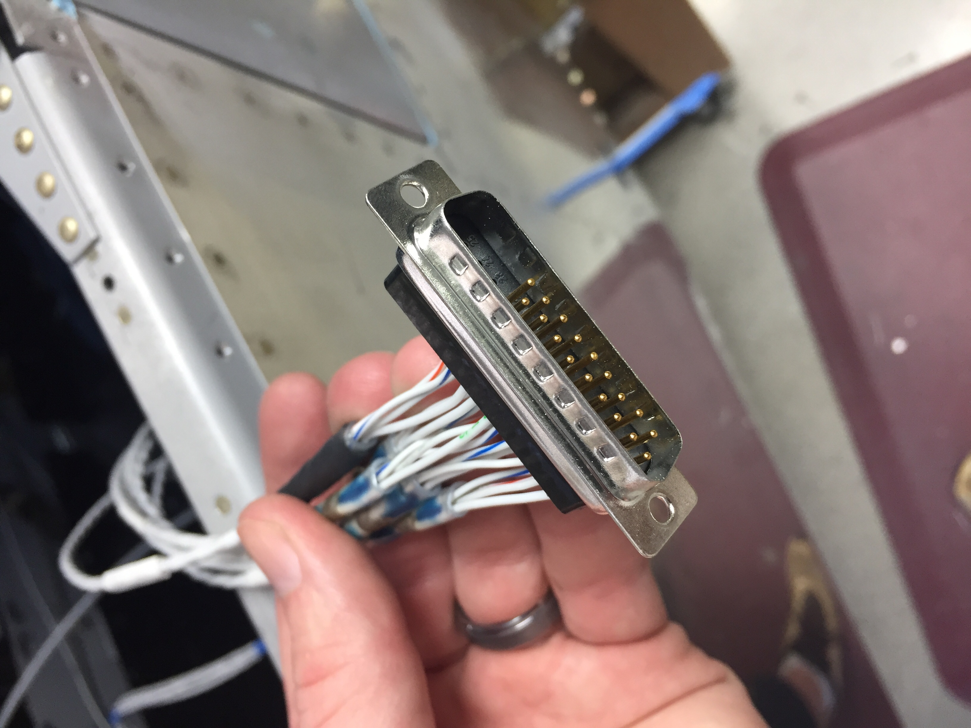
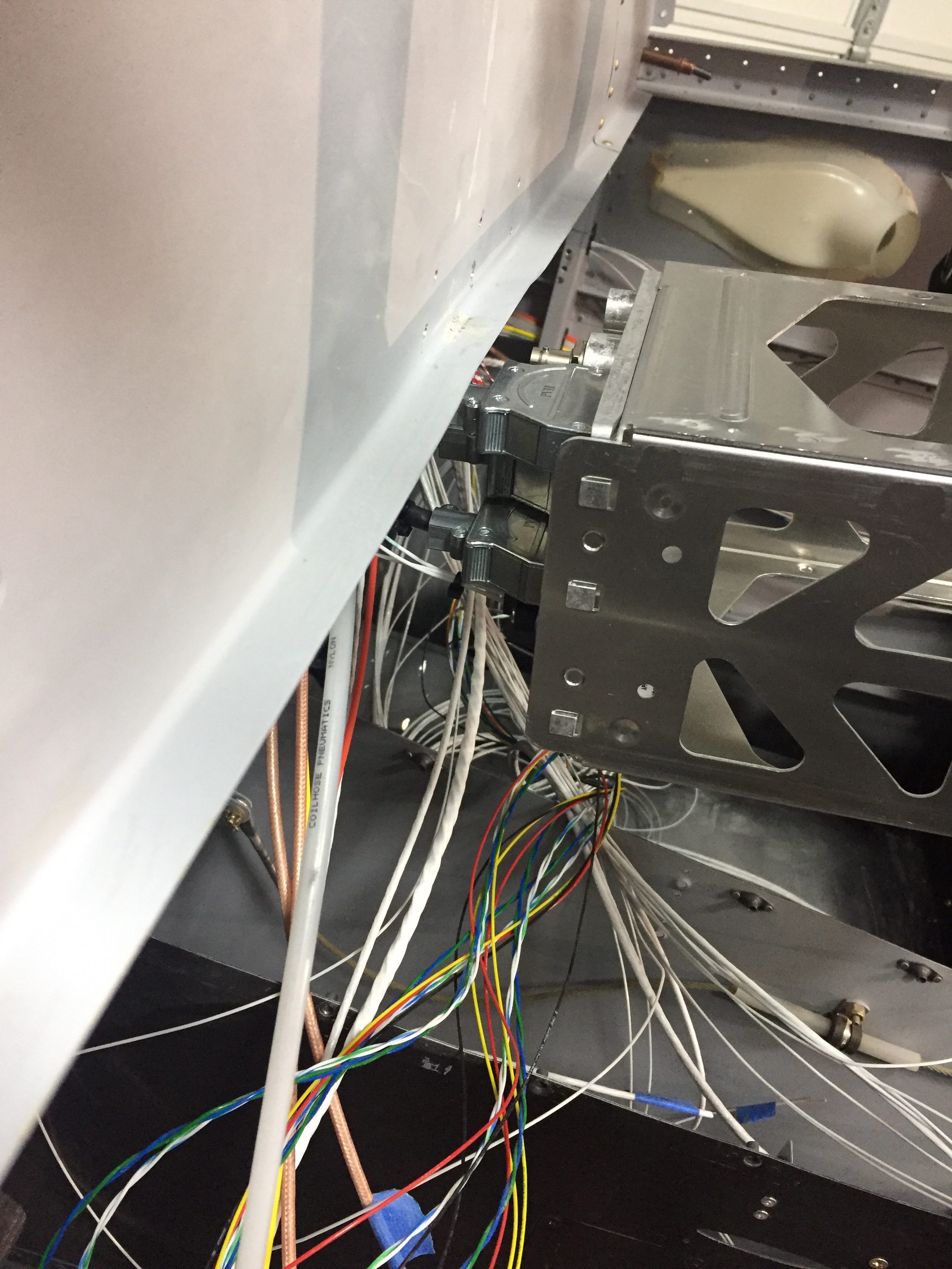
I first terminated the wires going to the ACM with pins according to the ACM pin out diagram.  I had to make a few customizations such as two pins per device for high amperage draws like the landing lights.  The ACM only supports 5 amps per pin, so you use two pins and a pigtail on the main wire.  This is where solder sleeves really come in handy and have proven more than their weight in gold from Amazon aircraft supply.  I took my time and ensured each wire was the proper connection / pin assignment as I went along.  Before you knew it, I was done with a 25 pin DSub.  I sort of wish I had used DSubs everywhere as they are just so easy to pin.  I completed the connectors on the ACM sans the switch panel, as I can’t wire the overhead until the support bar is in.

I also got most of the switches wired up on the main switch panel.  Since some of these switches don’t go to the ACM, I had to really map out where the wires ran and were going to be bundled.  I also had to get a bit creative on my configuration of the DPDT switches since I wanted off on the bottom and normal flight status on the top of the toggle throw.  This is picky, but I like everything needed to be operating in the up position and everything off in the down position as a quick way to cross check status of systems.  I have been and continue to use simple painters tape labels for the wires.  This will surely cause shock and awe on some builders who insist on heat shrink or diamond laser etching of each wire, but it’s working great for me and is quick and easy.  Once I pin the wire and connect it, I remove the label as long as it’s verified on my wiring schematic that’s a work in progress now that I’m actually wiring.

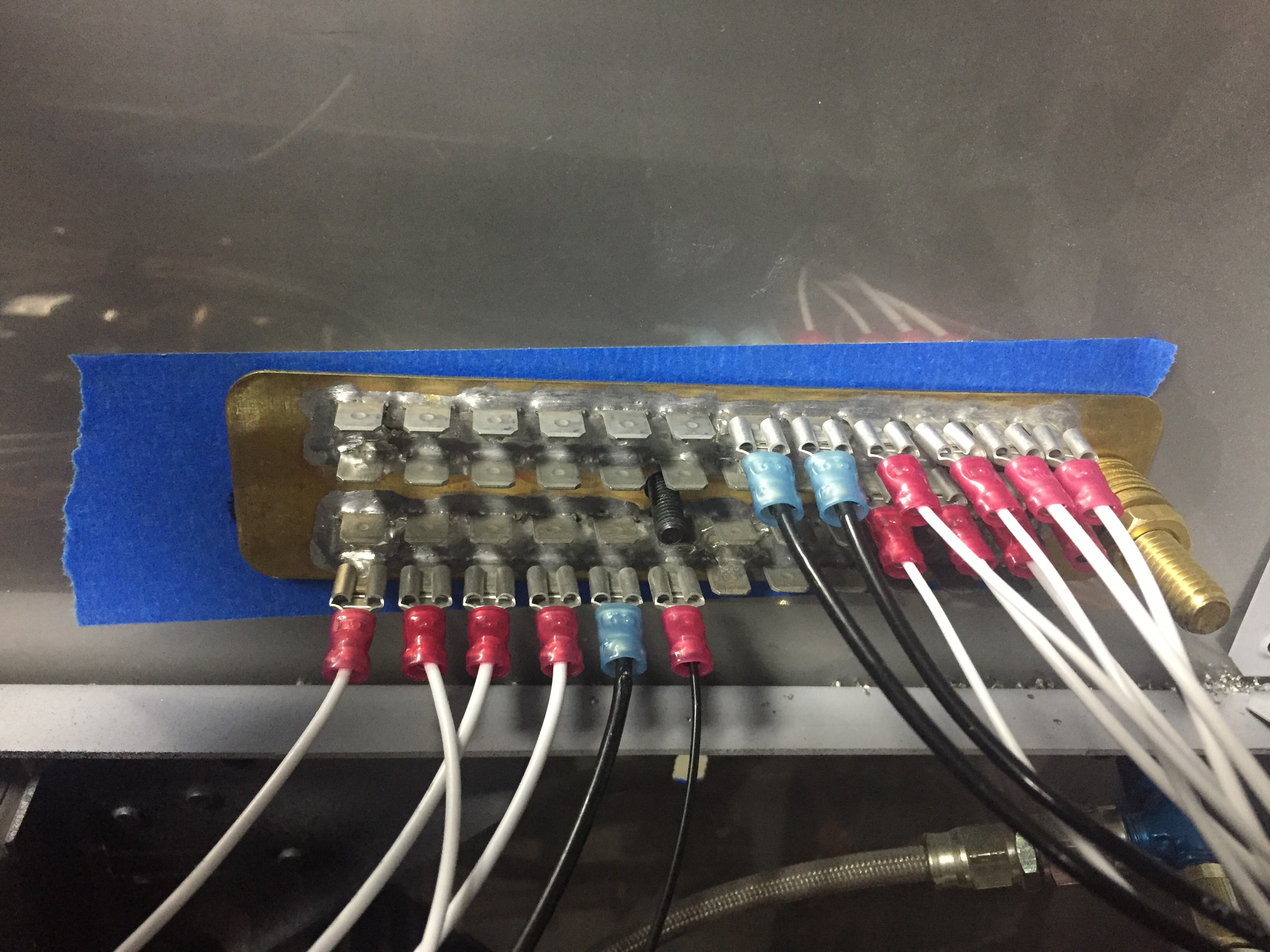
I will go back and do a permanent label on wires leading to the switch terminals just to make it easier down the road to R2 a switch.  On the grounding forest of tabs, I have a chart created that identifies each tab A-D, 1-12.  So down the road if I need to trace a ground or change something, I can refer to the diagram and see the assignment of B4 going to the taxi light, for example.  I still have some grounds to add, but I don’t have nearly as many as I expected.  I am thankful I went with the large forest, just to have the room available.

Ahh, but where to put that forest of tabs on the firewall?  Where to put anything on the firewall?  Well, after a few hours of staring at the stainless steel canvas and talking to myself at length, I embarked on an art project of painters tape and Sharpie markers.  I will admittedly have a lot of stuff mounted to my firewall.  I’m doing that to avoid extra weight in the back of the plane (since the aircon and O2 is back there) and to keep wire runs short.  Having two alternators, a ground power receptacle, and a few other items, the list of things is pretty long.  It’s a bit of a puzzle to figure out where everything needs to go, especially not having the engine yet.  Fingers crossed that staring at pictures and asking for a ton of measurements from other builders will prove sufficient in placing.  I held my breath and drilled the first hole for the grounding tabs.

Back on the inside, I laced all of the wires going to the cabin overhead in preparation of running them down the support bar.  The bar and now modified engine mount is at powder coating this week and should be a nice black by Friday.  I will wire the remaining lighting switches and interior lighting control module once the forward fuselage section is permanently installed with the support bar and top skin.

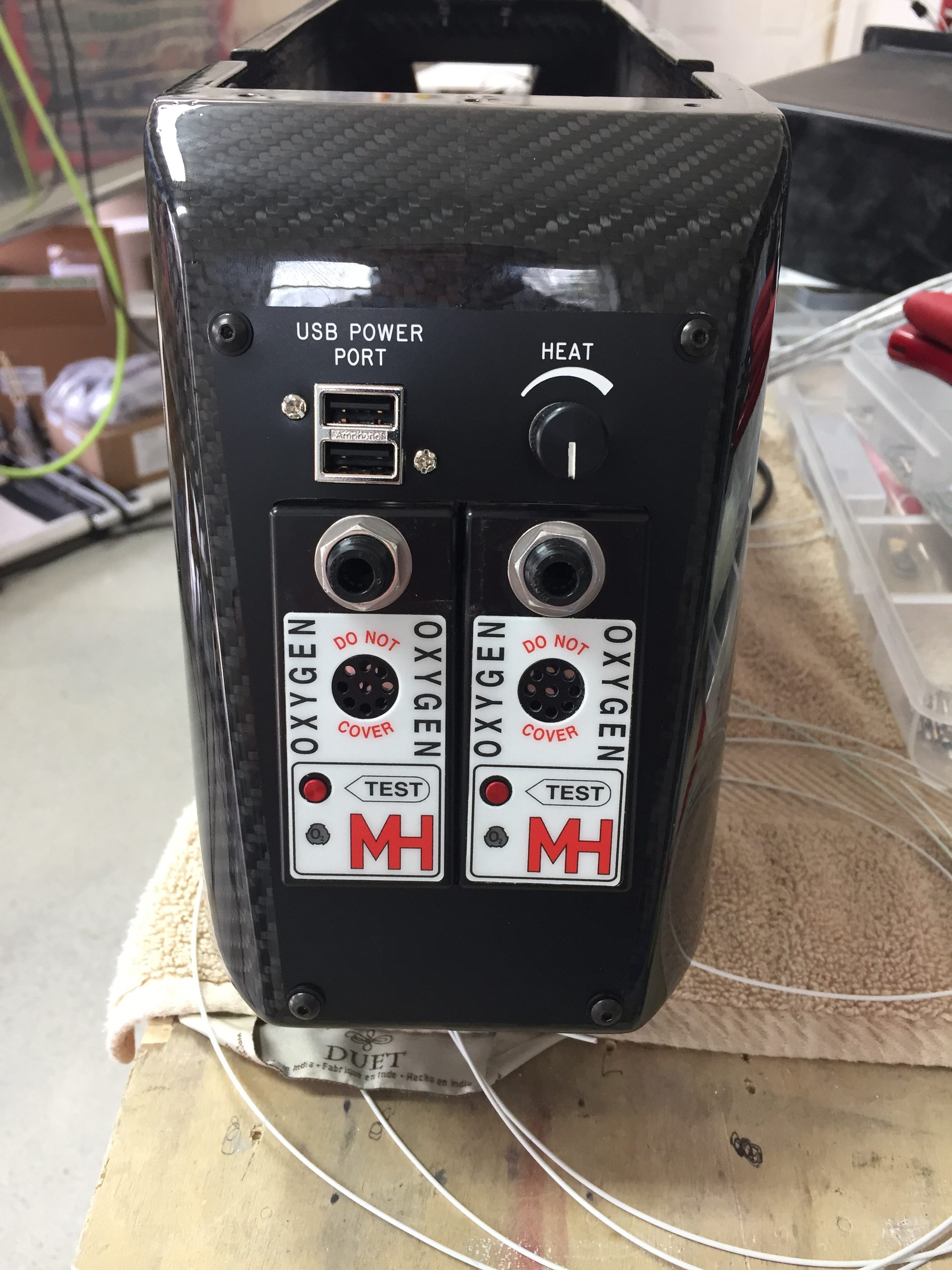
The center console wiring was buttoned up with a DSub to allow the console’s removal in the future without needing to pull all of the headset jacks out.  Again the solder sleeves make easy work of pinning out the shielded wires.  I also put on the rear seat panel and final installed the rear O2 ports and USB power port.  It will not be back light like the front, but figure rear seat pax can turn on their task light to see if needed without affecting me as much.  It came out very nicely and I’m getting excited to see the armrest cover that Aerosport is finishing up with the seats.

I finished all of the wiring I could and left it all bundled as I pulled the subpanel and premade harness out of the plane one last time.  On the bench, I had to move the IBBS battery down about an inch to clear the defrost fans and installed nutplates for the clamps.  Attention will now turn towards the tunnel and getting all of the associated plumbing done before putting the avionics in for good.

Spaghetti and Brains

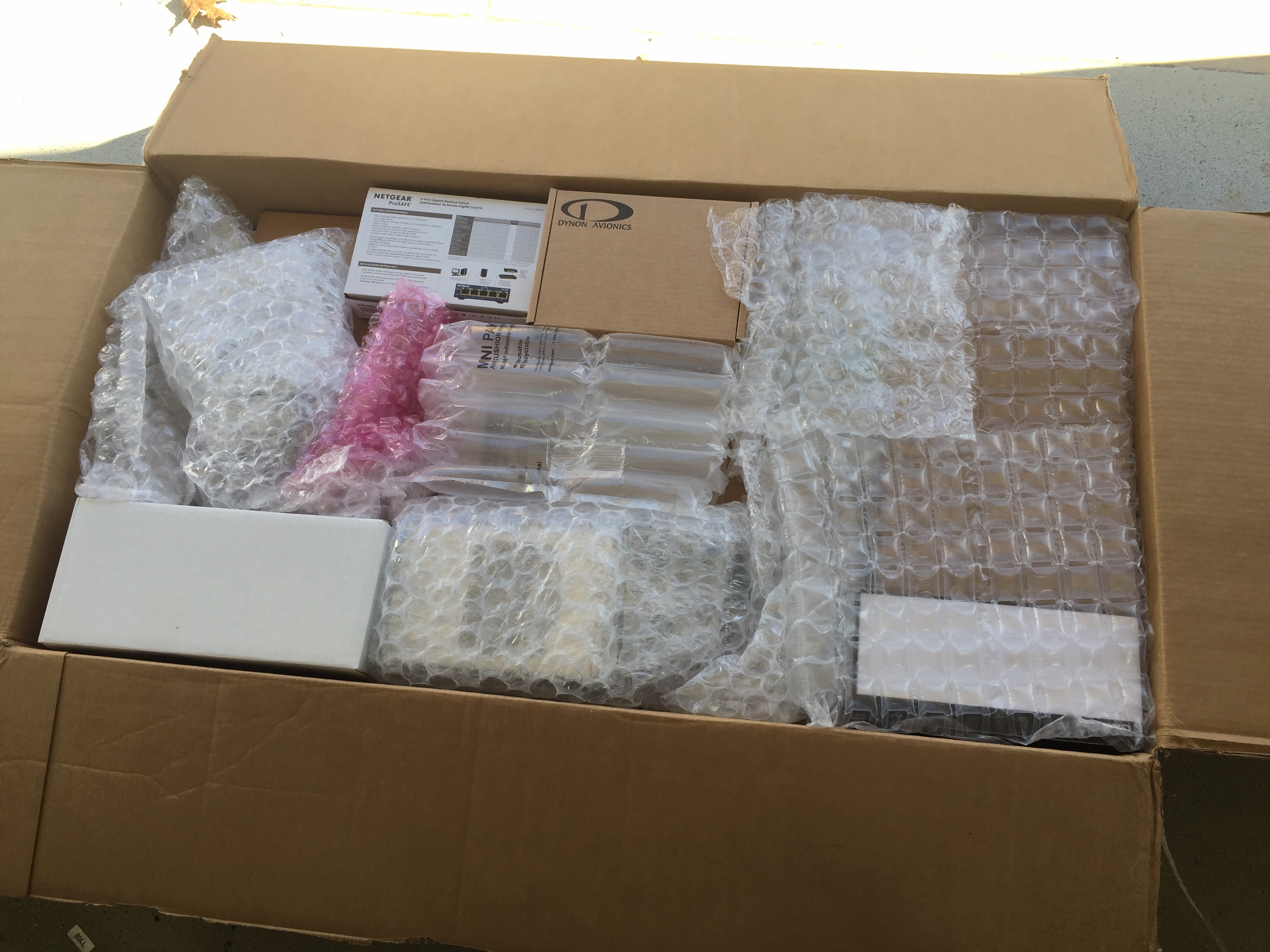
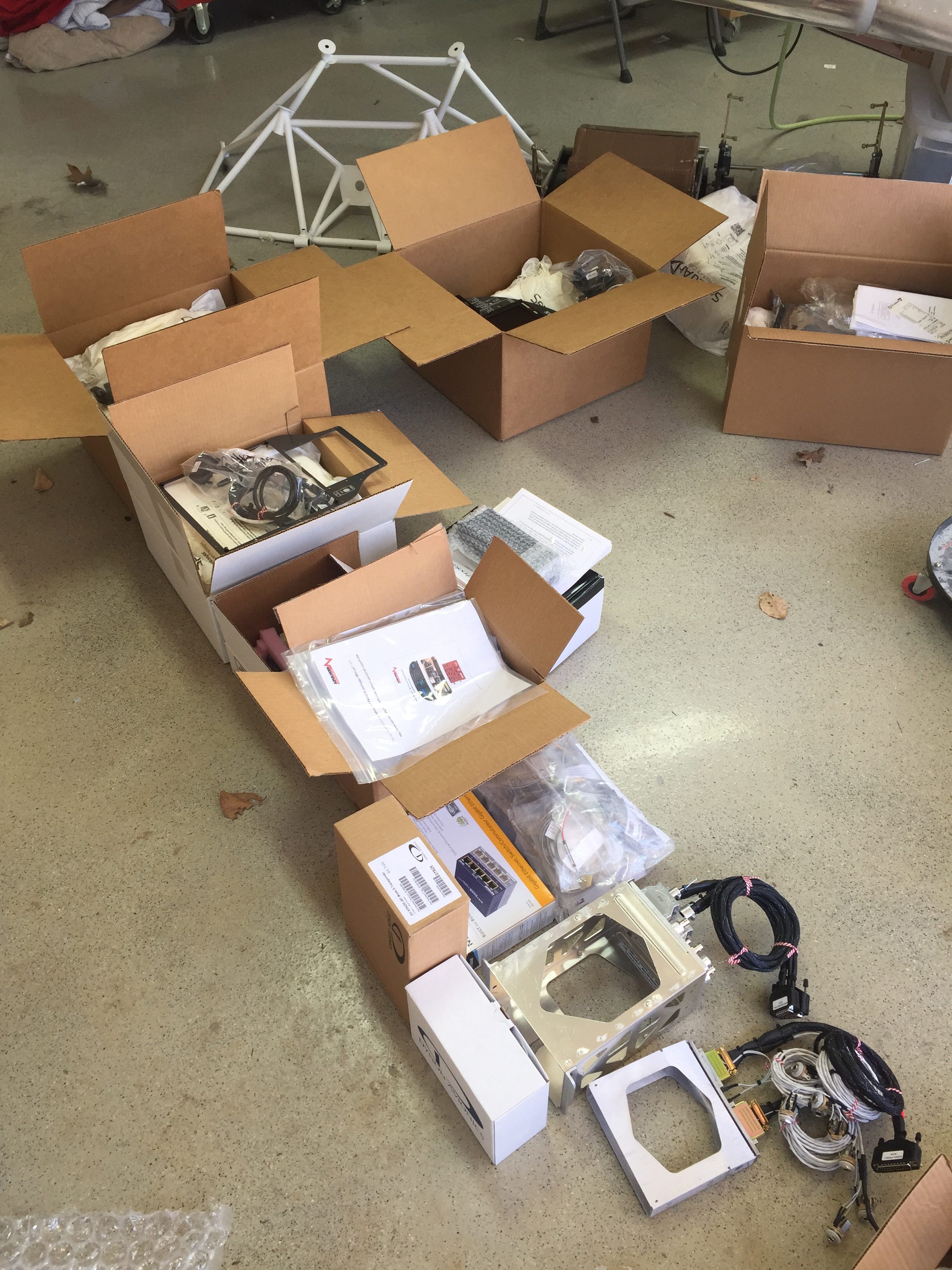
Exciting times have arrived in the workshop with the arrival of a big, very valuable, cardboard box from Advanced Flight Systems.  At long last, the brains of the avionics came in which means it is time for me to get down and dirty with wiring.  It took most of an afternoon to unpack and inventory all of the contents but everything I ordered was in the box.

Let me side bar here by saying I am extremely happy with AFS and everything they provided along with all of the questions they answered.  I still found myself questioning a few things and forgetting a few things, however.  The Avidyne does not come with an antenna that costs an additional $325.  Didn’t know that.  I thought I was getting XM as I talked about it many times but it wasn’t on the quote or the order.  Didn’t know that.  Some of the quick panel wiring was different than what I had expected and planned.  Didn’t know that.  The autopilot does not have a go around function.  Didn’t know that.  I’m just saying be cautious, open, and aware that it’s never a one stop shop on avionics.  As much research as I did, I still missed a few things and had to ask a lot more questions and dig in manuals a lot more after I thought I had it all figured out.

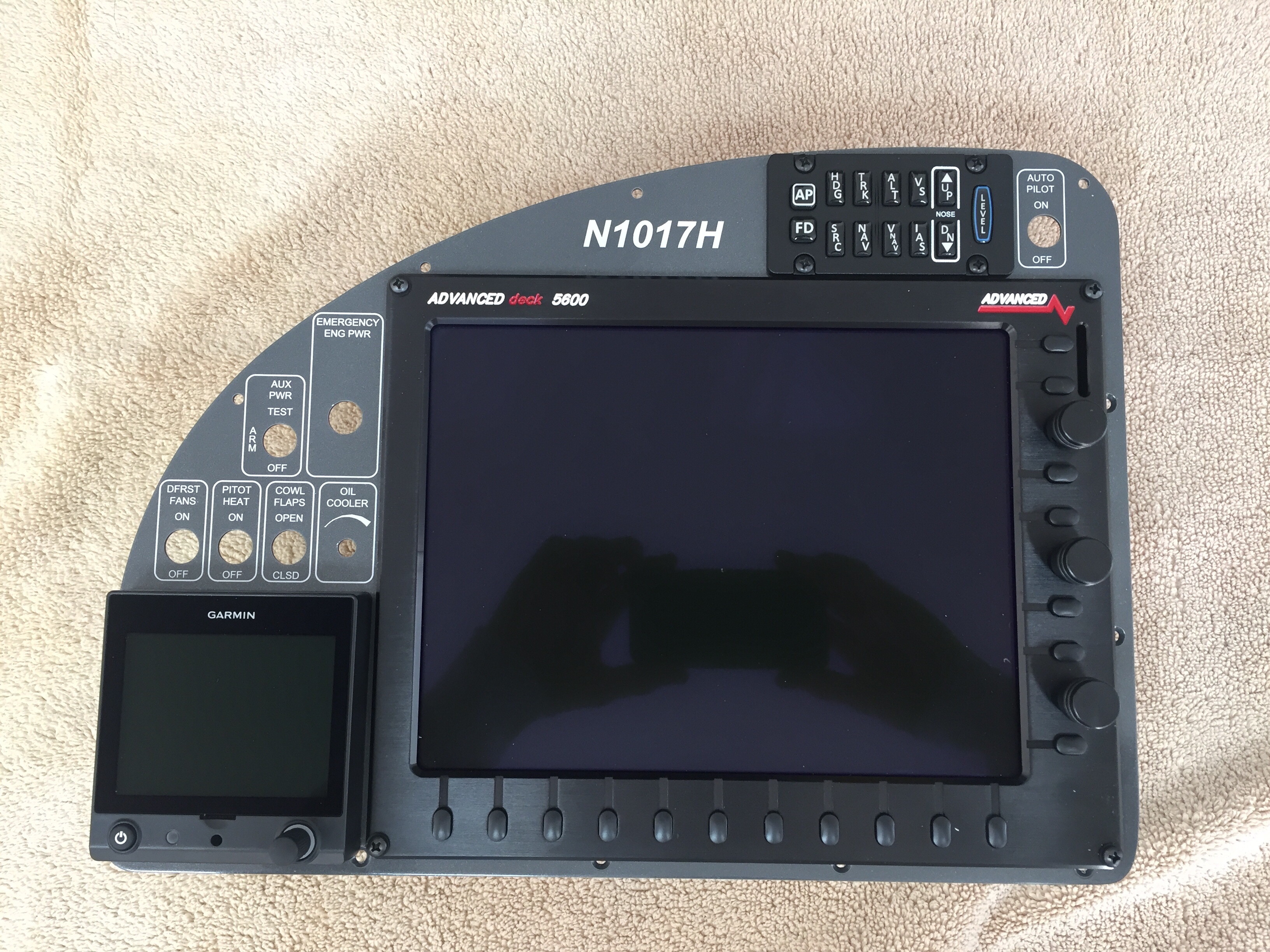
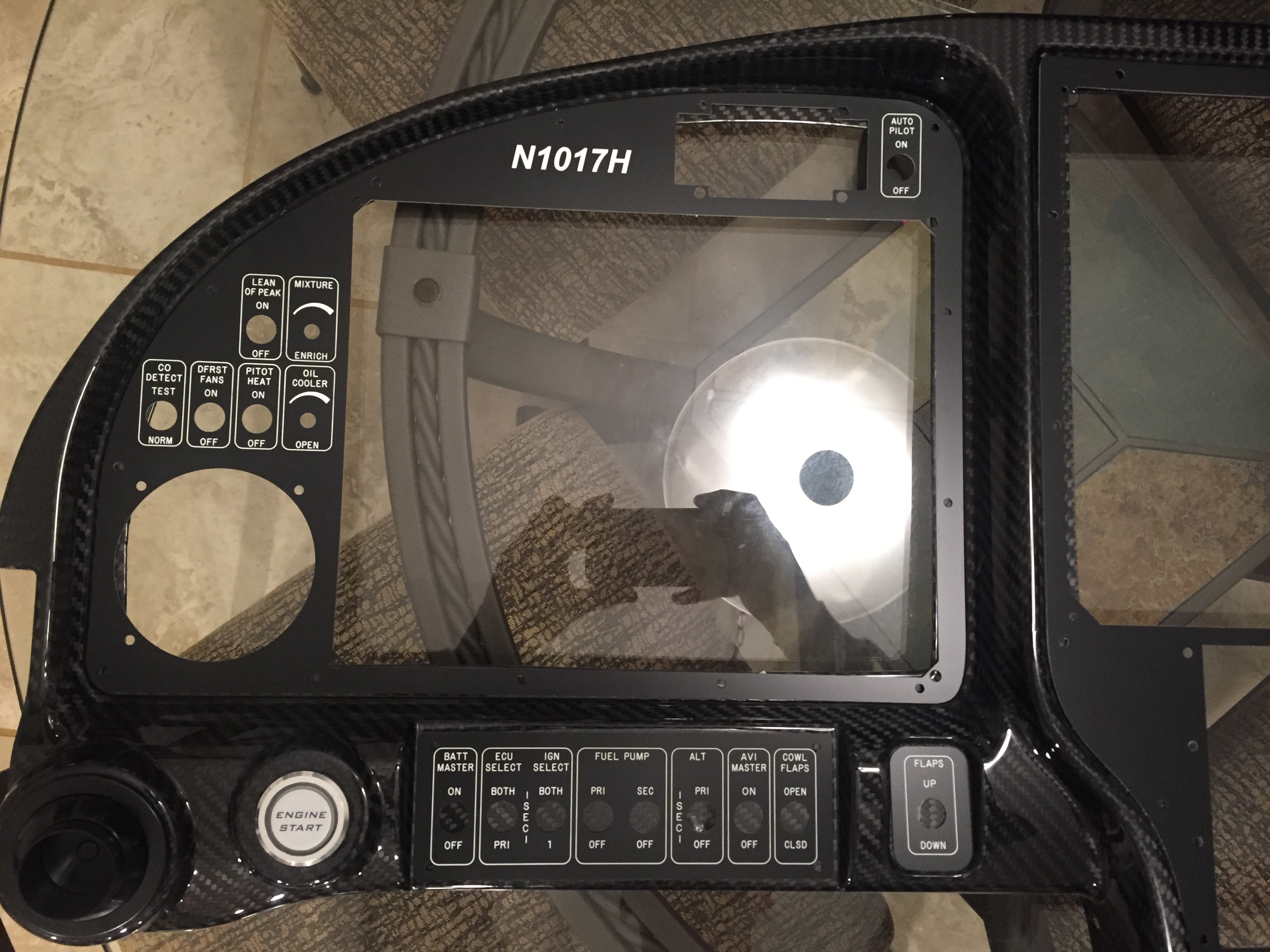
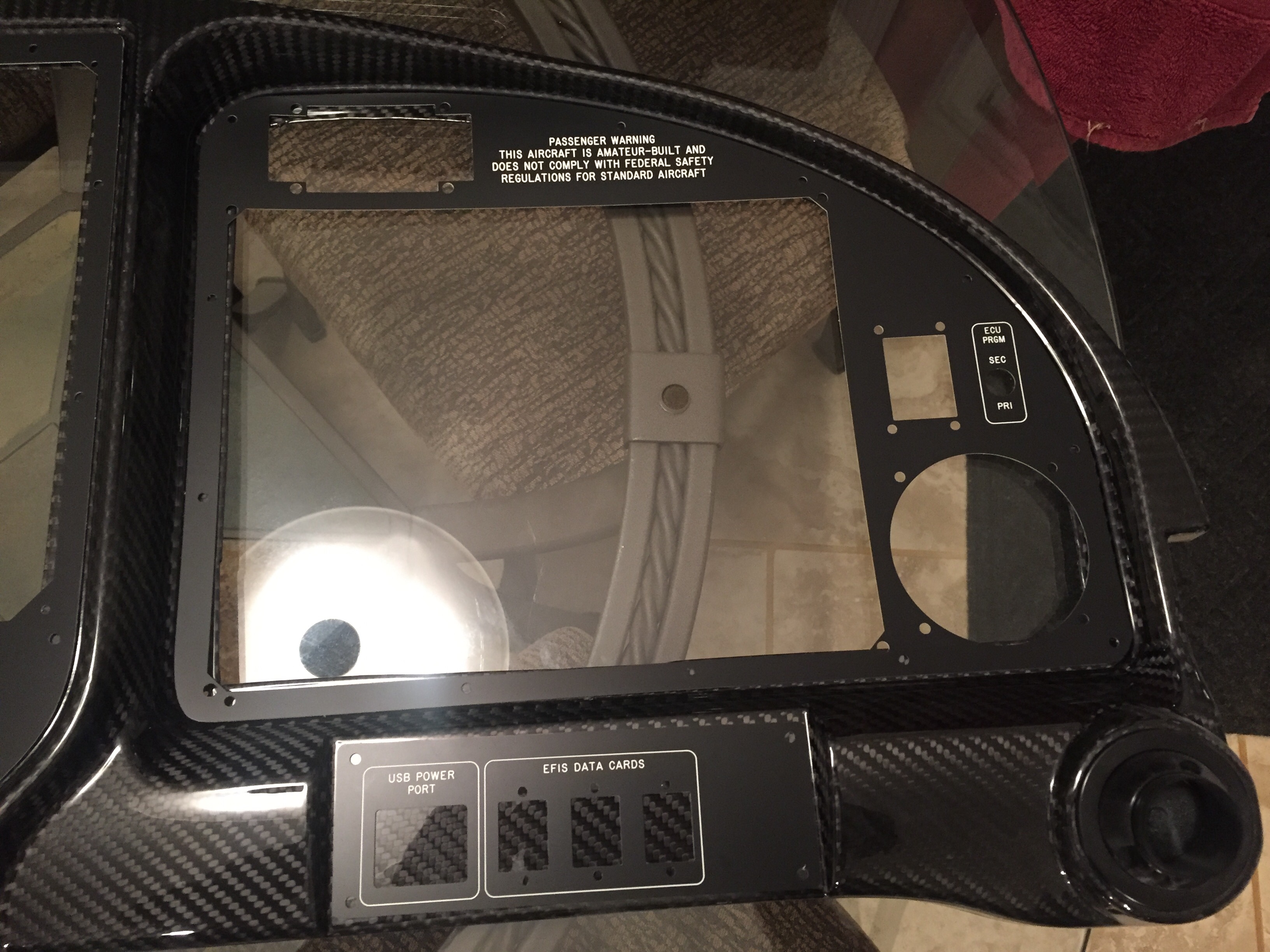
I laid everything out to get a good look at it and tried my best to keep the drool off of the expensive electronics.  The panel inserts are absolutely jaw dropping, especially with the screens dropped in place.  The paint and silk screening was perfect and very well done.  All of the cut outs were just as my panel design had laid out and the components all fit perfectly.  Unfortunately, I’ll be covering up the nice paint and finish with the acrylic overlays to create the back lighting.  Had I known the acrylic would not be easily removable, as I do now, I wouldn’t have put Rob and AFS through the hassle of painting and labeling the inserts.  My apologies, guys.

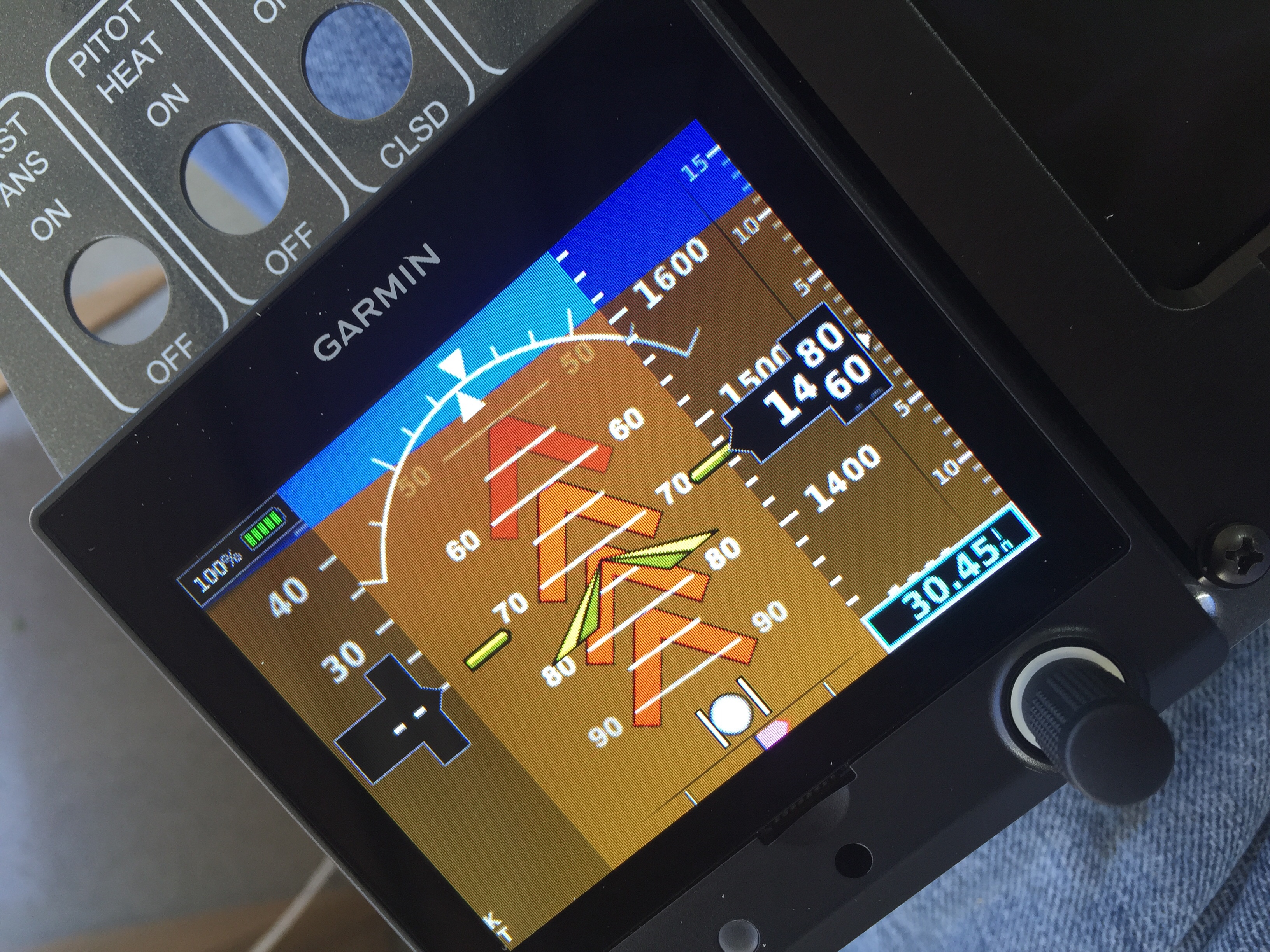
It’s hard not to dive right in, plug it all up and flip the master switch on to start playing.  But I practiced self control and waited until I opened all of the boxes before I started pressing buttons and making airplane noises.  I nearly dropped the unit when I pushed the power button on the G5 and it turned on!  I wasn’t expecting it but the backup battery is installed and she came to life.

AFS did an amazing job of creating wiring harnesses for most of the components behind the panel.  This includes everything from the ACM (their version of the VPX) to the screens, radios, GPS, ADSB, TX, and a few other remote boxes.  It leaves several connections that have to be finished by the builder such as switch inputs (since I’m using custom toggle switches, not the AFS quick panel switches), aircraft front and rear which encompasses lights, pitot heat, etc., trim/flap, and AP servos.  Fortunately, I had the AP servo harness made and installed from the first shipment so that was an easy kill.  I have spent quite a bit of time pulling wires from the needed locations towards the front of the fuselage in preparation of the avionics arriving.  I finished up the wing root harnesses and a few other odds and ends to get the below starting point.

My first task was to fit the Aerosport metal frame behind the carbon panel into the forward fuselage.  I took extra time to make sure everything was positioned properly and drilled a few reference holes to keep it all lined up correctly.  Both the frame and the carbon will need to be trimmed for the screens and inserts.  I set out on the middle insert first since I was concerned about the IFD 540 tray interfering with the subpanel.  As luck would have it, the 540 cleared the subpanel by about 1/2″ so no need to modify the subpanel at all which was a relief.

Then I started laying all of the remote components out on the subpanel which was like putting together a puzzle with missing pieces.  There are fewer boxes with AFS than with Garmin, and they are typically smaller, but it’s still a lot to fit back there.  I wanted to facilitate future maintenance and access to each one, so thought carefully about how I’d get to each box once the plane is finished.  I also tried to keep in mind wiring runs and guidance on how/where to mount each box compared to others.  I am using nutplates on everything I can to make it easy to remove later, so need to keep that in mind on the back of the subpanel.

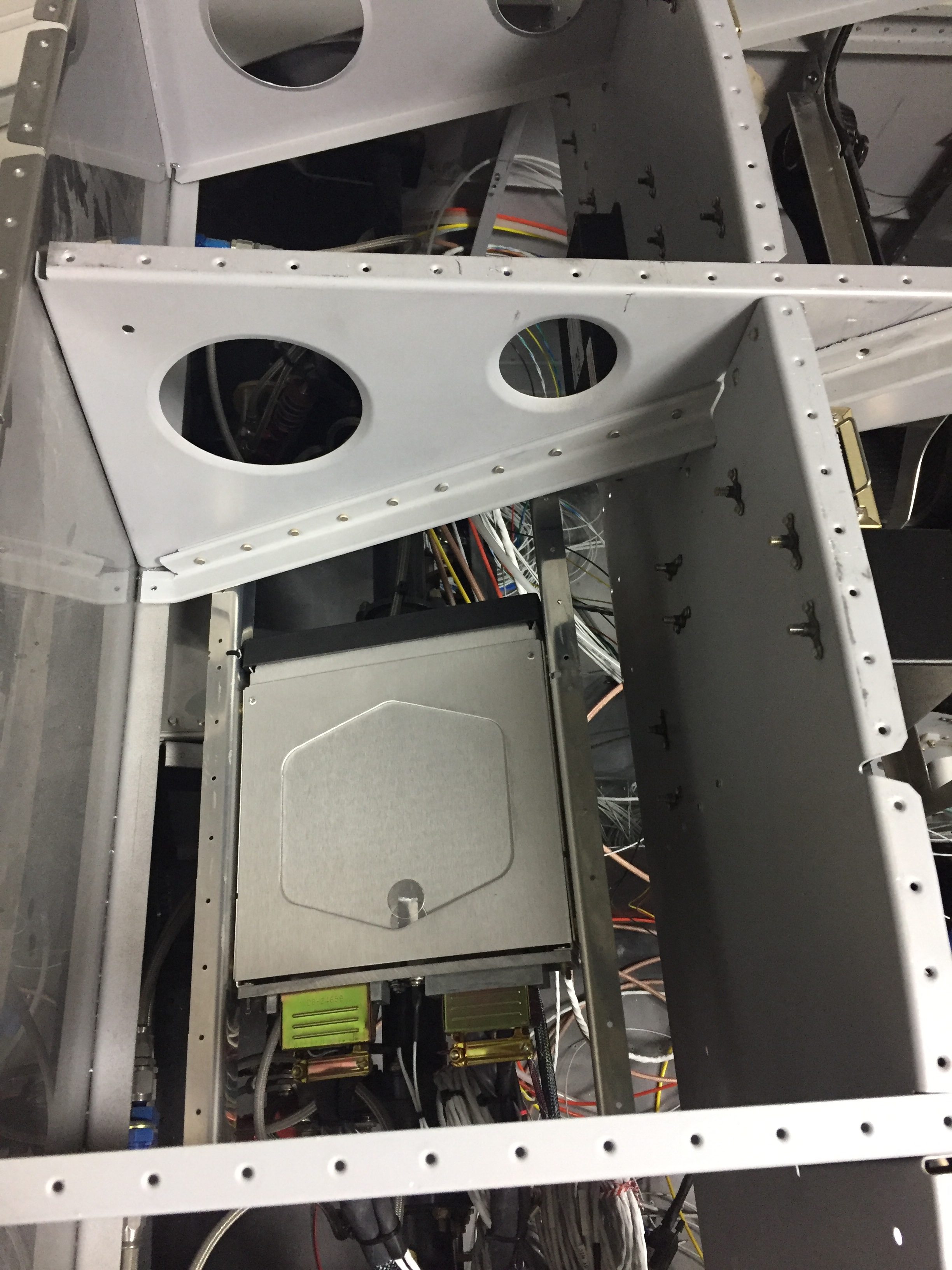
I found that some things just don’t fit and the audio panel was a great example.  With the tray and connectors on the back plus the suggestion of keeping it away from high current devices and wire runs, I decided to create a rail system and mount it behind the subpanel.  The ECUs for the SDS system will also mount behind the subpanel.  I ensured enough space was between the two for the audio panel to slide out of the tray and for connectors to have room when wiring is complete.

It took two evenings to get everything laid out and nutplates installed so the subpanel could go back into the airplane.  I’m pretty proud of shoving all of these boxes back there and can still easily get to pretty much everything.  I won’t say I’ll never be upside down ing the floor getting to anything, but it will be minimized.  I put all of the premade harnesses in place to get an idea of wire runs that will be needed.  There are a lot of wires in this airplane!  I can’t imagine how much time it would have taken me to build up the harnesses that AFS made up, let alone the assurance they were bench tested with no smoke!

Next up will be pining the wires from the airframe and fitting the inserts to the panel.  Stay tuned!

Back that light up

One of my most exciting side projects on the plane is to have a truly unique instrument panel.  From the start, I have wanted a back light system similar to fancier aircraft out there and to pretty much every car out there.  Glareshield lighting, post lights, or dome lights just don’t work or look the same, so I wanted something better.  Ed Krantz did a great job using LED strip lighting but had to do a lot of work to get it working.

As briefly discussed in THE ART OF DESIGN, I decided to experiment with electroluminecent panels.  These EL panels are almost paper thin, flexible, and can be cut in all sorts of shapes.  Better yet, they are dimmable and have a uniform light output.  After a successful prototype on the overhead console panel, I pulled the trigger and ordered the full layout of the EL panels and the laser engraved acrylic overlays.

The EL panels came from Marc at Lightkraft via Etsy.  Marc was phenomenal to work with and took a personal interest in the project.  We had to iron out some dirty details on orientation, power leads, size constraints, etc.  I wound up taking his limfacs and finessing the panel layout a bit around the EL panels to make sure everything lit up as desired.  I also had to be strategic on where the power leads would be located along with the two edges that are unlit where the leads run.  On those two sides, it’s about 3/16″ that is unlit and cannot be cut, so positioning those correctly was key.  The other two edges could be cut and shaped in any way needed.  Finally, holes in pretty much any shape can be cut out of the middle to allow for switches or components without affecting the rest of the EL panel.  On any cut edge, the panel must be sealed to prevent oxygen from ruining the EL material.  Marc suggested clear acrylic nail polish which was easy and quick.  The prototype was done in white, but I wanted the final product in all blue.  Marc did a great job taking the 1:1 sized PDF I produced from my CAD design and producing the panels.  He provided a transformer based on the total surface area of the panels so all will be wired together and be on one dimmer.

Since AFS helped design and is producing a quick panel for me, the metal inserts for the four major sections of the Aerosport 310 panel are being cut and silk screened by AFS.  I wanted that as a back up to the EL panels just in case those didn’t work out or fail and are not replaceable sometime down the road.  After finalizing the design with Stephan at AFS, I sent the same CAD design to Matthew at Aircraft Engravers and requested all the panels be cut from black on white acrylic, just the same as the overhead console test panel.  Matthew was able to cut all component, switch, and screw holes then laser engrave all of the markings.  The acrylic panels have a self sticking backing so applying them for good is as simple as pulling off the backing and sticking them on the metal panel!

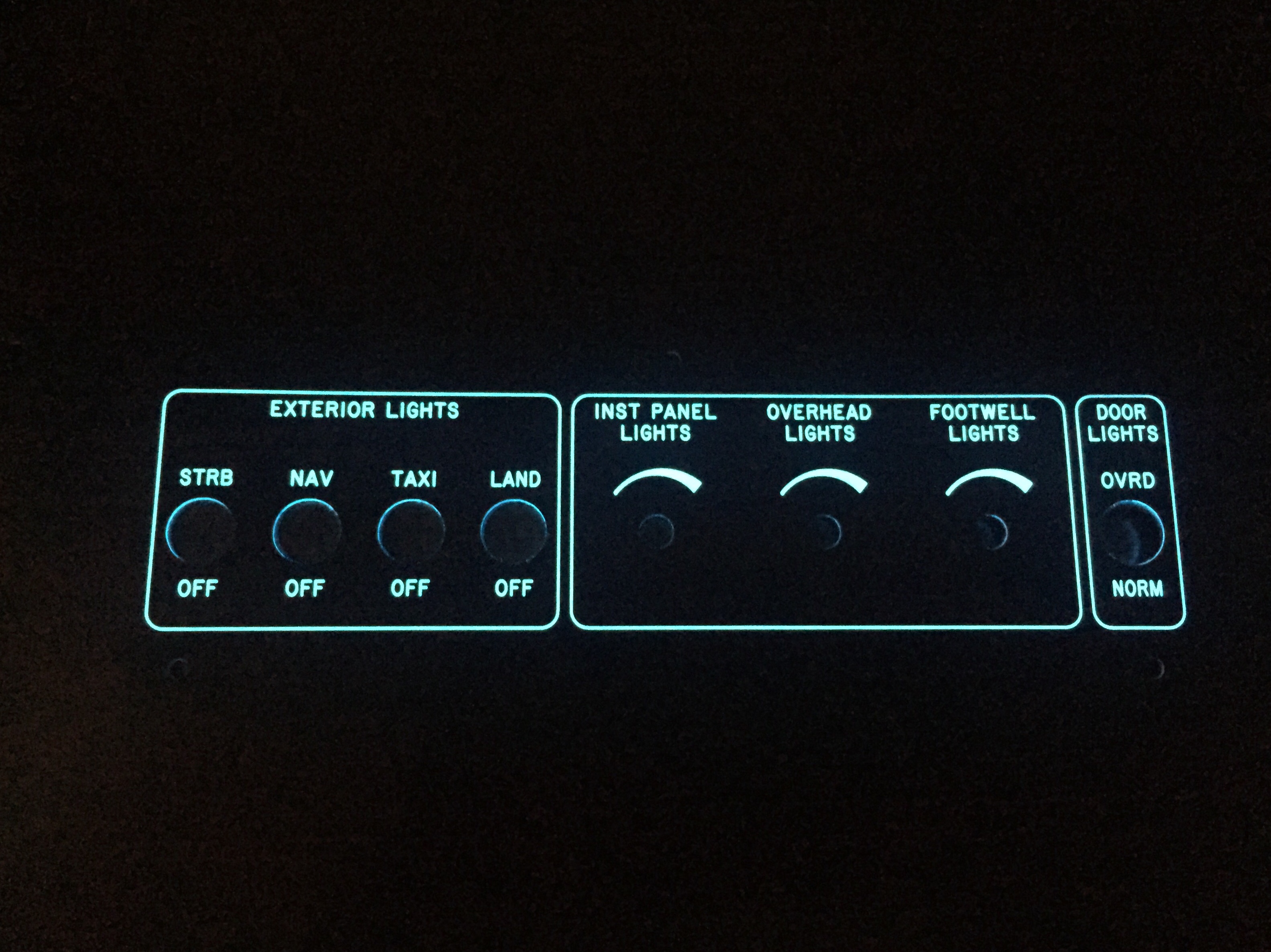
I took some time to ensure each EL panel fit the area needing back light and trimmed a few spots to clean it up.  I used a 5/8″ punch to punch holes for switches and dimmers in the EL panels.  The idea was to avoid the EL panel contacting any metal avoiding shorting and any interference noise the panels may translate to the air frame.  From what I can tell, neither is necessary as metal doesn’t seem to bother the EL panel and test flying the prototype in the Diamond yielded quiet radios and headsets.  After all of the holes were cut and trimming was completed, I turned into a little kid and played with everything in the dark to make sure all engraving was properly lit.

Next task is to cut a relieve for the power leads to rest in.  Since the wire is soldered onto the EL panel, it needs to slip either to the edge or behind the metal panel so that it is all flat once completed.  The areas where EL panels are not near and edge, I cut a slot for the leads to fit through ensuring no exposed lead touches the aluminum.  Several locations will require the leads coming out from the side of the acrylic panel and going into the carbon fiber structure through a slot.  Those are a bit tough to cut out but with patience and a lot of though prior to cutting, it works just fine.  The main switch panel and flap switch panel were the toughest ones.

To install it permanently, I cleaned the metal backing panel and positioned the EL panel with 3M clear double sided tape (the same stuff Van’s recommends for trailing edges).  This is really just to hold it while placing the acrylic overlay on top.  The backing is removed from a small section of the acrylic overlay so that I have some adjustment playing the overlay on the metal panel.  Once everything is lined up just right, I removed the rest of the backing and pressed the acrlyic down evenly.

The end result is a sandwich with the acrylic on top, EL panel, then metal panel at the back.  There is just a slight thickness difference over the EL panel, but not enough to be noticeable without really inspecting up close.  If you’re doing that, keep your judgments to yourself!  Switches and dimmers are installed just like you would anything else and before you know it, I was able to screw the panel on the overhead console and fire it up.  I went ahead and wired all of the switches and had the dimmer pots ready to go, so the overhead console and panel is now complete pending black screws coming from AFS!

Overall, I am really impressed with the result and happy I did the project.  It wasn’t cheap, costing about $1000 with most of that coming from the engraved acrylic overlays.  The EL panels were about $200 after all said and done.  The acrylic would have been much cheaper if I had only done the areas around each switch or back light panel, but I wanted a uniform look across the cockpit.  I would absolutely recommend it to anyone wanting a little extra light and wow factor on their build.  The CAD work was fairly simple and fun as was putting it all together.  I can’t wait to get the rest of the avionics and get the whole thing fired up.  She is going to look stunning in the dark!

In Over(my)head

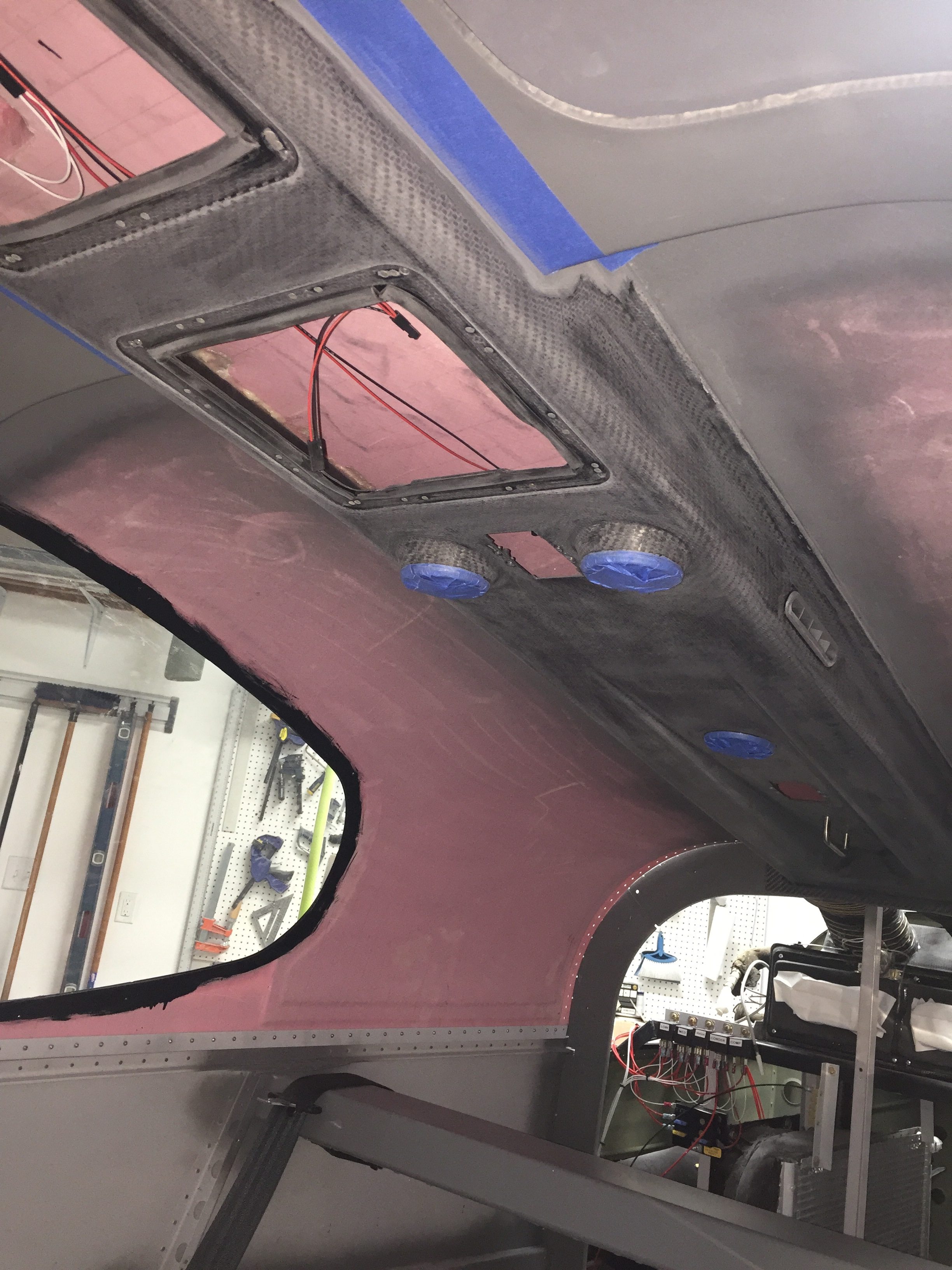
Just when I thought I was nearing the work on the inside, all hell breaks loose.  As I had put masking tape on the overhead console to protect the paint from scratches caused by fitting the headliner base, I wound up setting myself pretty far back by ripping off chunks of paint with the tape.  Now we all know it’s probably not the paint’s fault.  It’s mine.  Why do I do stupid things like not properly prep the surface and not prime?  Seriously.  WTF Tim?  Get your crap together.

Bottom line, I knew as soon as I painted the overhead it was fragile.  The paint had already chipped off a few spots around the metal insert panels and I was concerned that it wouldn’t hold up to normal wear and tear.  I chewed on having a professional painter take it and strip the entire interior but then decided against it, not wanting to give up control.  On the surfaces where I properly prepped and applied the paint, I was very happy with it.  I like the idea of being able to do spot touch ups with a spray can down the road.  All of the interior matches.  All those plus the thought of someone inadvertently sanding through filler while trying to remove the current paint helped me climb in with a razor blade, pile of sand paper, and a neck brace to start working overhead.

After about three hours of work, all the paint was off the overhead and everything had been sanded down with 120 grit.  Even though Aerosport says 320, I found that it wasn’t really marking the surface much, and I want the paint to stick this time!  I took my time around the vents and areas of the cabin top where I knew the paint/primer was strong such as the door frames and switch panel.  As I was removing the paint, I could obviously tell where areas were better than others.  Around the door frames that had been scuffed and near the switch console where I had primed, the paint was a real bear to remove.  That gives me hope I can do it right.

This time, I’ll use tack-free to wipe down the entire surface very well and remove any contaminants (something I didn’t really do before) then use an adhesion promoter while putting the primer on.  I have the fuselage all cleaned out from dust (again) and need to finish the touch ups on the door at the same time.  I’ll also spray the baggage door panel.  I’m not going to jinx myself and say that will finish the interior this time.

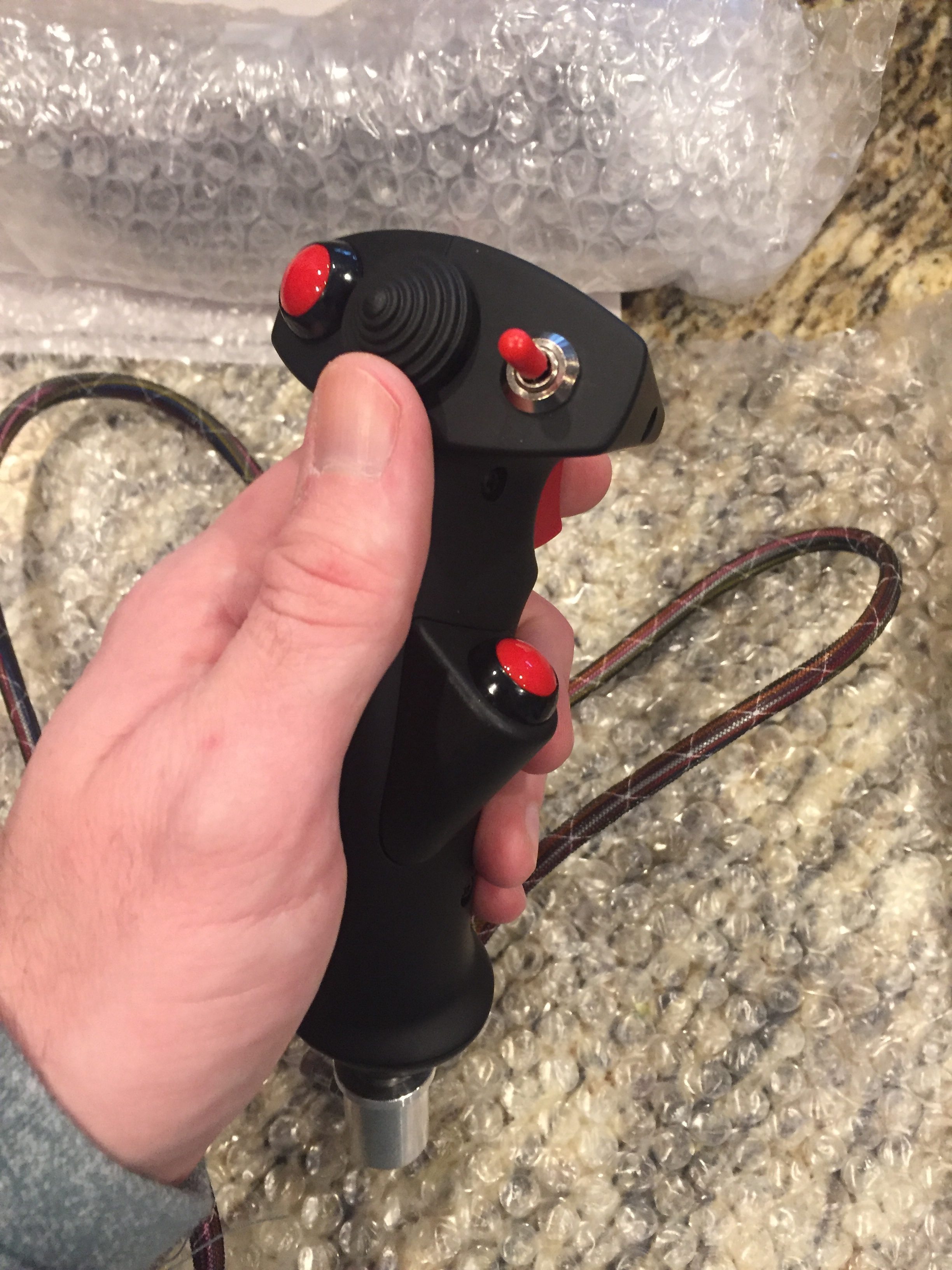
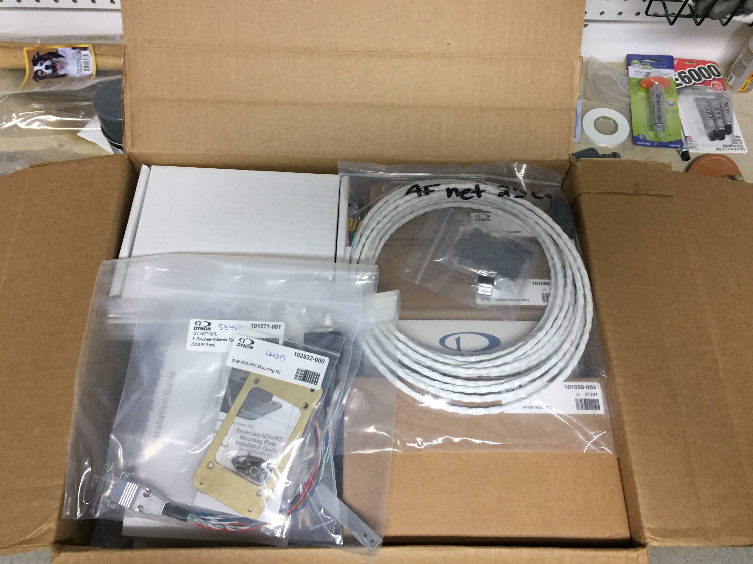
Meanwhile, my first two very expensive boxes of avionics have arrived!  The lesser of the two from Tosten had my two stick grips in it which led to lots of button pushing, trigger pulling, couch flying while making airplane, gun, and missile noises!  I’ll try to get a video sometime.
The big box was from Advanced Flight Systems as a prelude to the full panel being shipped in a week or two.

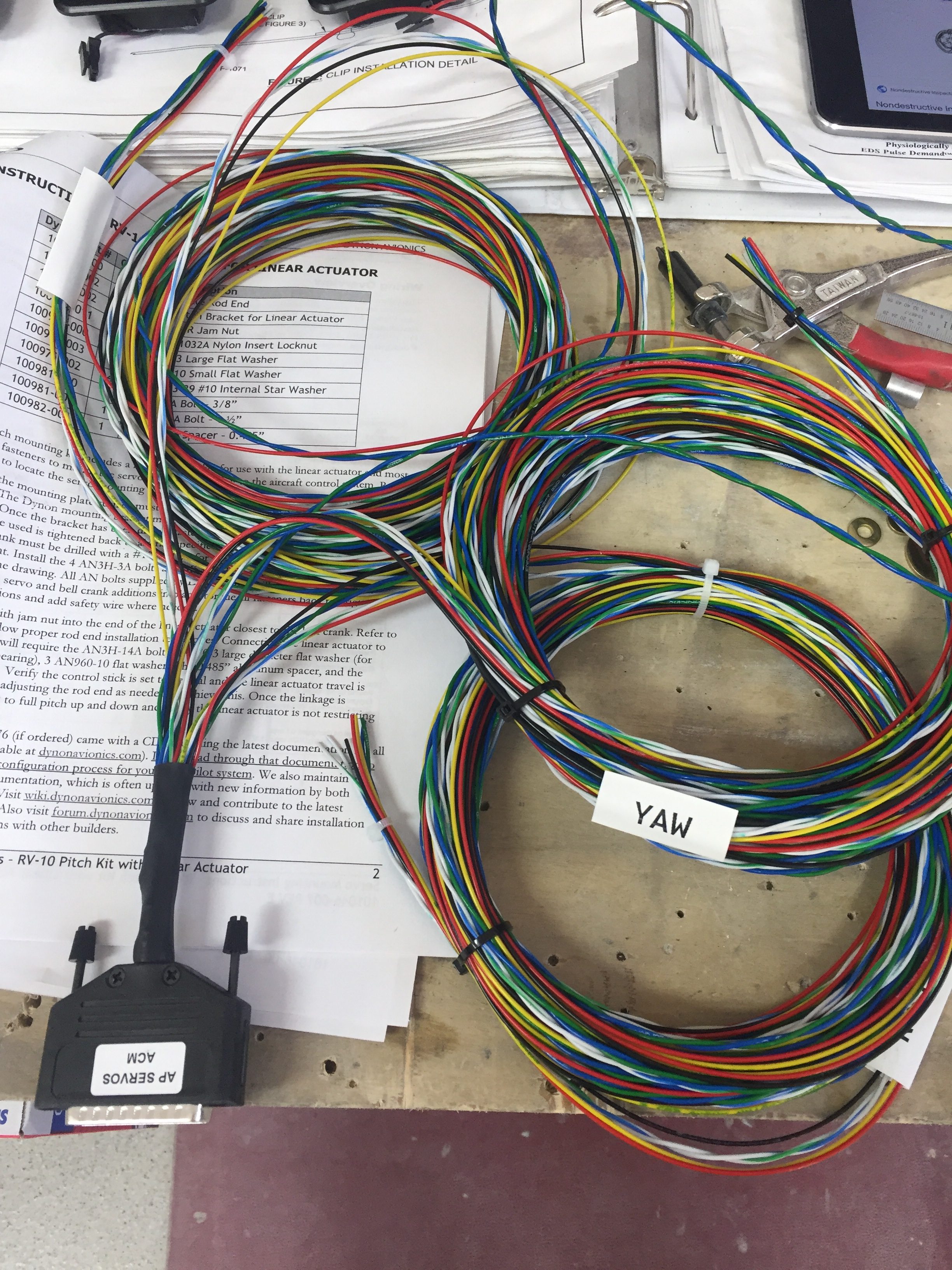
They were nice enough to ship me some advance components and harnesses such as the ADAHRS, servos, and EMS among a few other things.  I first ran the autopilot servo wire harnesses and already appreciate the value of having AFS wire the majority of the avionics.  I pulled 21 wires in about 10 minutes that are already pinned on one end.  That task alone would have taken a day to measure, cut, label, pull, and pin all of that.  Once the servos are in place, I’ll use the supplied pins to finish the connections.  I also pulled the SV network cable that will run to the ADAHRS in the tail cone.  I essential tripled the amount of wiring in the aircraft in less than 30 minutes!
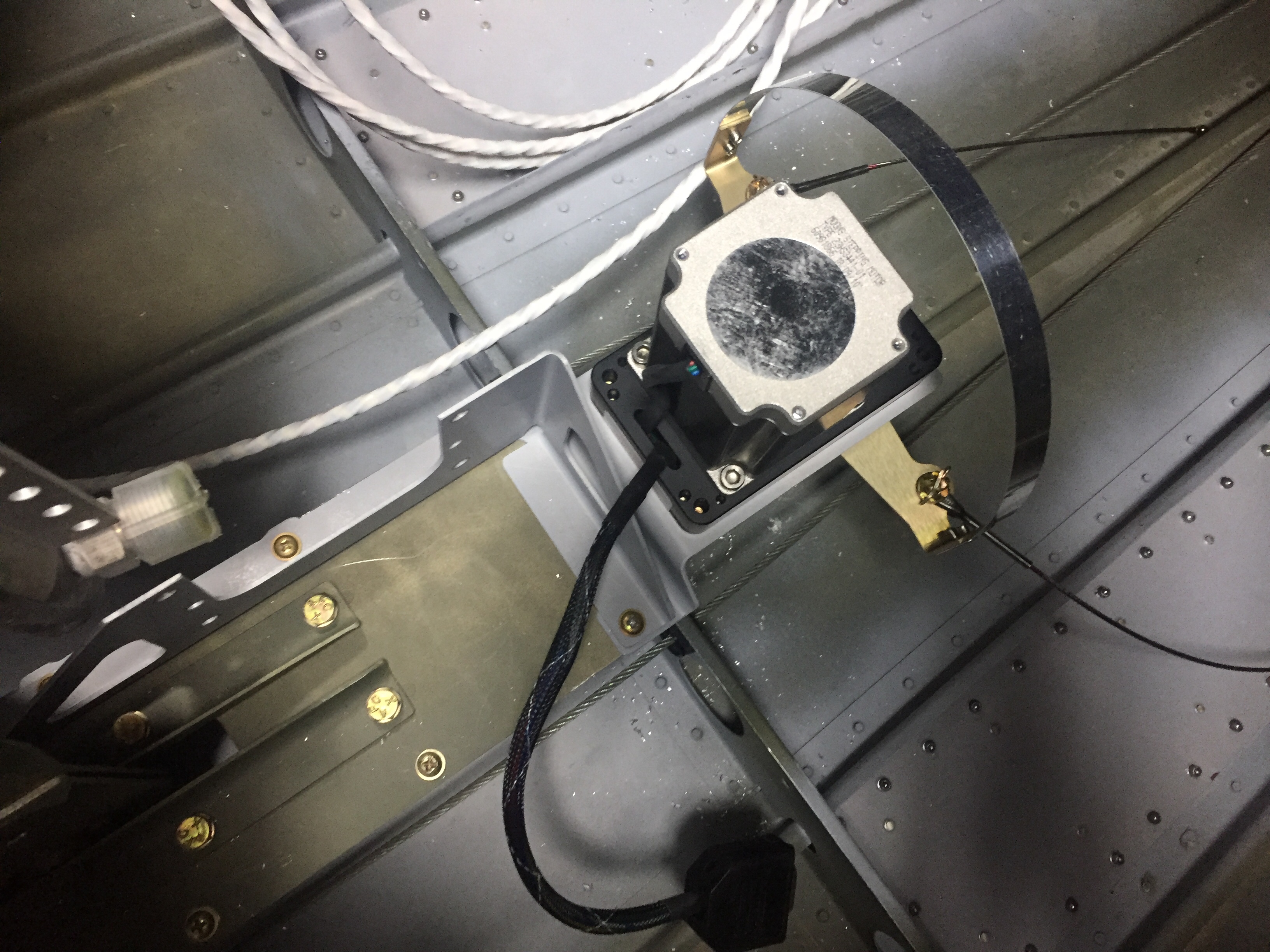
My yaw damper mount arrived from Van’s so I set about installing the pitch servo mount and yaw servo mount back in the tail cone.  Woof, what a pain in the ass to get to at this point.  Future builders, buy this stuff early and put it in when building the tail cone!  By sheer luck or divine intervention, the AC condenser clears the pitch AP servo by about 1/8″.  I really lucked out, because I had no idea how it would all fit when I redid the AC.
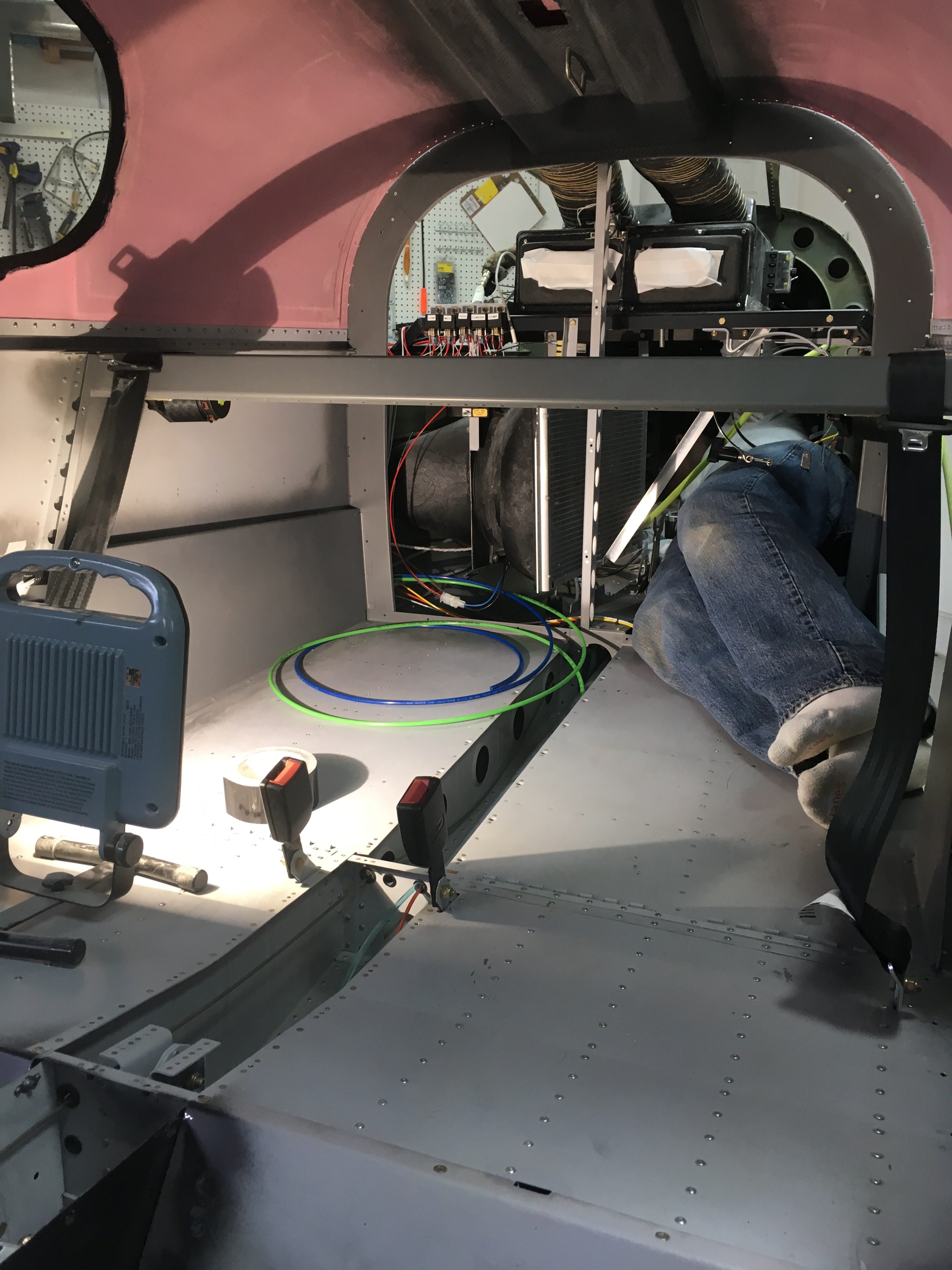
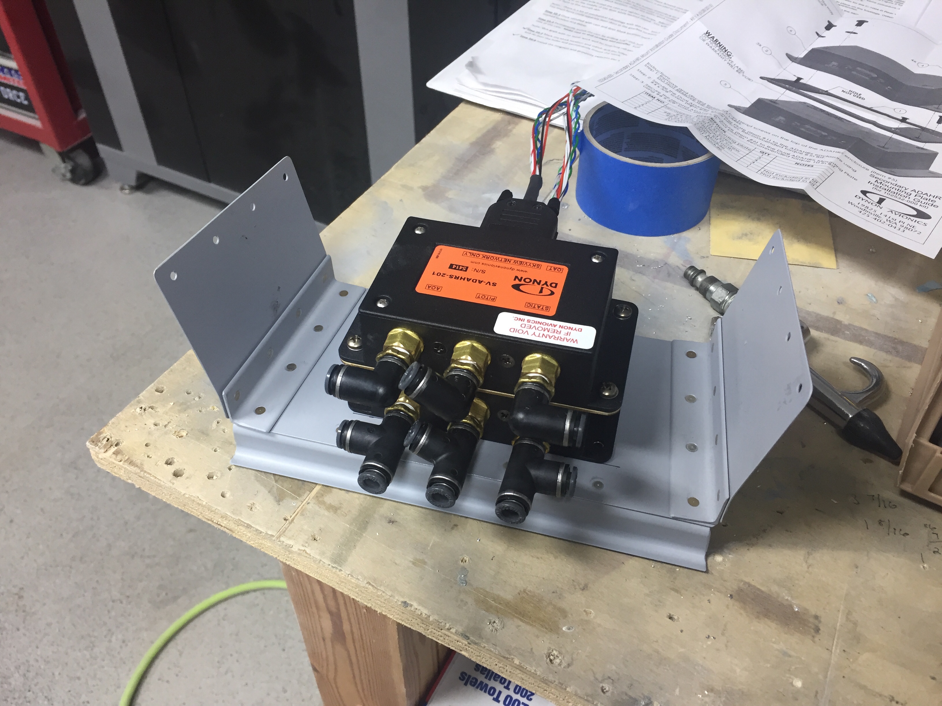
I do not enjoy laying in the tail cone so I made a list of everything needed to be done for the next and final time during the build getting back there.  I decided to remove the O2 tank to make more room and was able to mount the ADAHRS tray fairly easily.  I managed to get it within .75 degrees on all axis by sheer luck, again, but I’ll take it.  I routed all the tubing and installed the pins on the wiring to hook the splitter up to the harness from the front.  I took the time to lace all the wiring and installed a few grommets back there.  It all cleaned up very nicely in the end and I’ll just need to shimmy back again to hook the rudder cables up to the yaw servo once the tail is installed.

Bringing up the rear

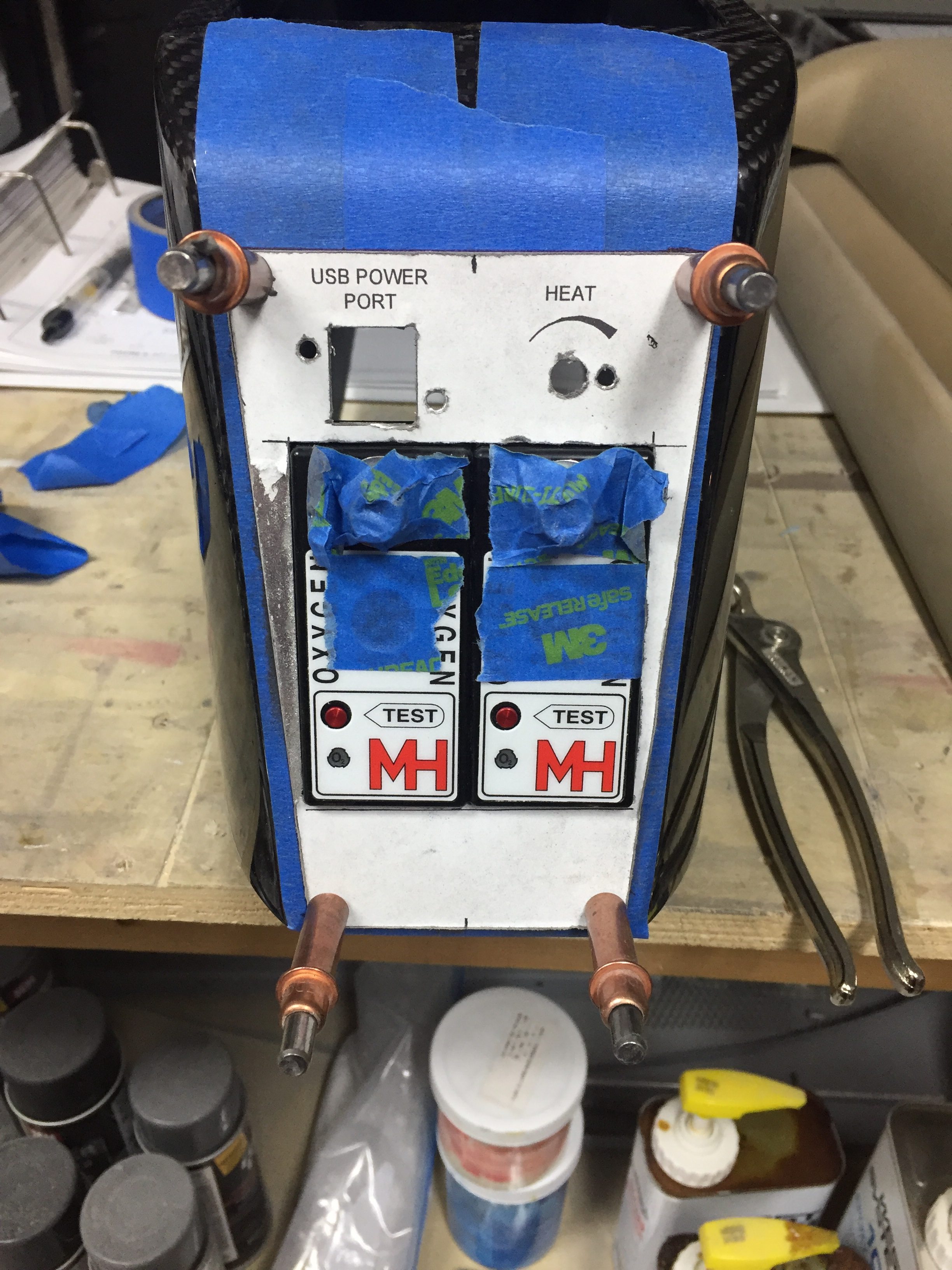
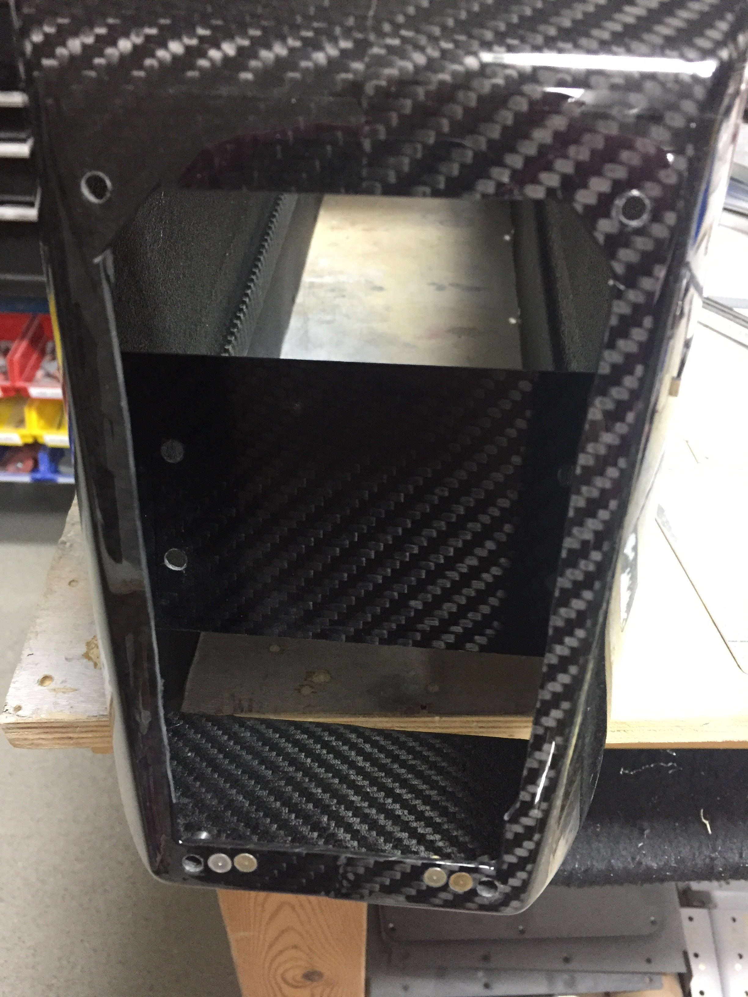
Now that the carbon fiber bits are cleared, I went to work on the rear panel for the back seaters.  My original plan was to mount the oxygen ports, a USB power port, heat control rheostat, and headset jacks into the rear console but it all just wouldn’t fit.  The O2 ports had to stay there, as I didn’t want them in the side panels due to lack of room, so the headset jacks got the boot.  I drew up a layout based on the measurements of the rear panel area.  The carbon is too thick and rigid for the ports to cleanly snap into so I will use AL with a matching acrylic overlay just like the instrument panel up front.  I was able to keep the power port and heat control on top.  I won’t be back lighting these as there isn’t much room and I figure at night a task light can be turned on easily.

I did need to come up with a way to secure the O2 ports, so I used a scrap piece of carbon and installed a few nutplates before epoxying it into the console.  I had to trim the brackets of the O2 ports so they fit side by side as well.  In the end, it’s a nice fit and still allows easy removal for maintenance.

I used some advice from TCW Tech folks to add a source selection switch into the controller for the rear heat servo.  I had to cut the rheostat off of the circuit board and ordered two matching ones from DigiKey, wiring them up with the control wire going to the switch.  This will allow me to control the rear heat using the rheostat mounted up front or give control to the rear seaters.  Testing with the multi-meter confirmed the desired function so those were tucked away for future install.

Now that I knew where the rear O2 ports would exactly be, I could continue the plumbing of O2 lines.  That also led to running the wires to the O2 ports, power port, and rear heat rheostat.  I fabbed up a few bushing holders to attach to the tunnel and ran everything down the left side.  The front seat headset jack holes were drilled inside the armrest cubby and the wires will be secured onto the tunnel cover.  I placed connectors on all of the wires so that the tunnel cover and center console could be removed for maintenance without needing to remain attached via wires.

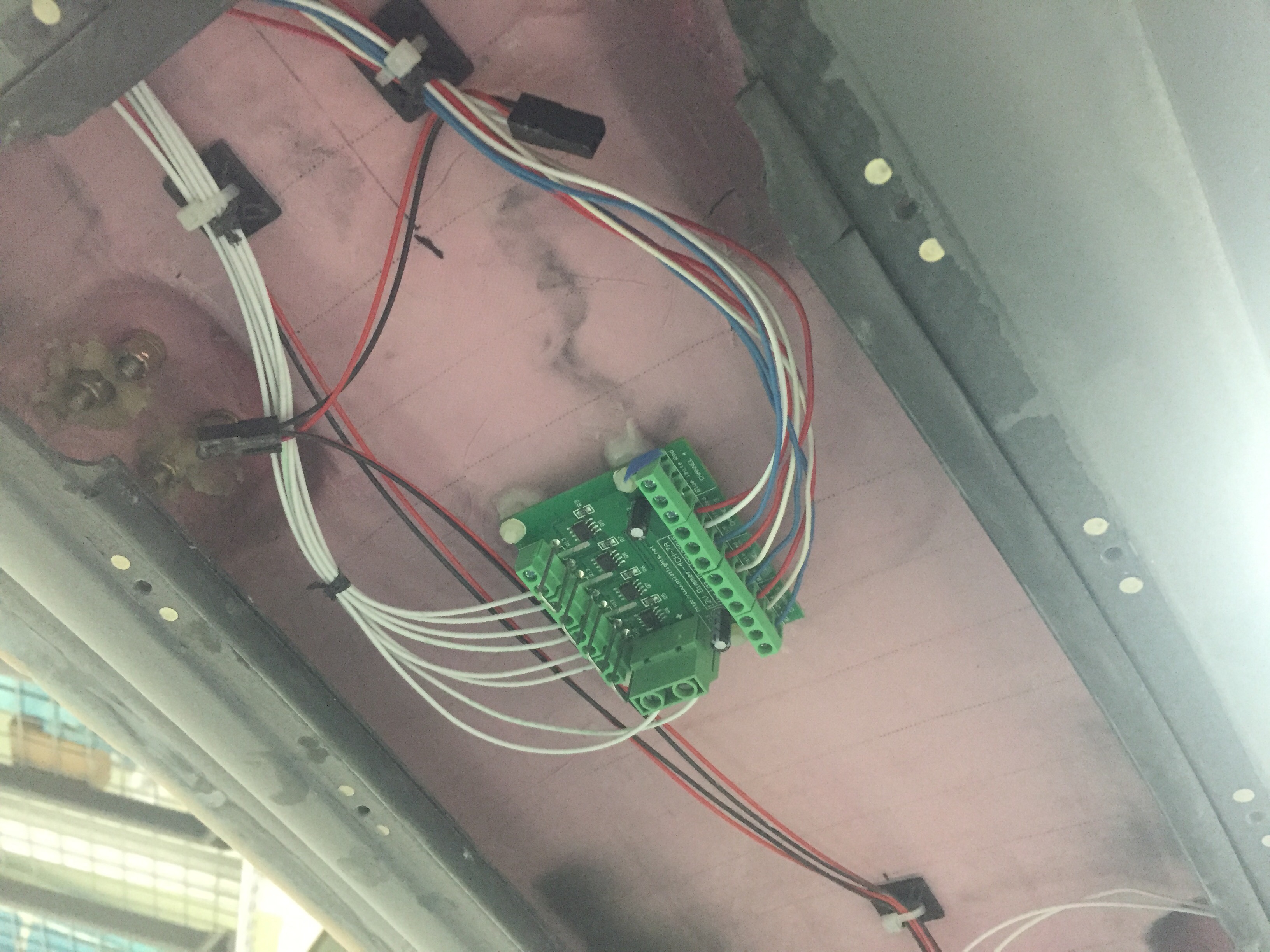
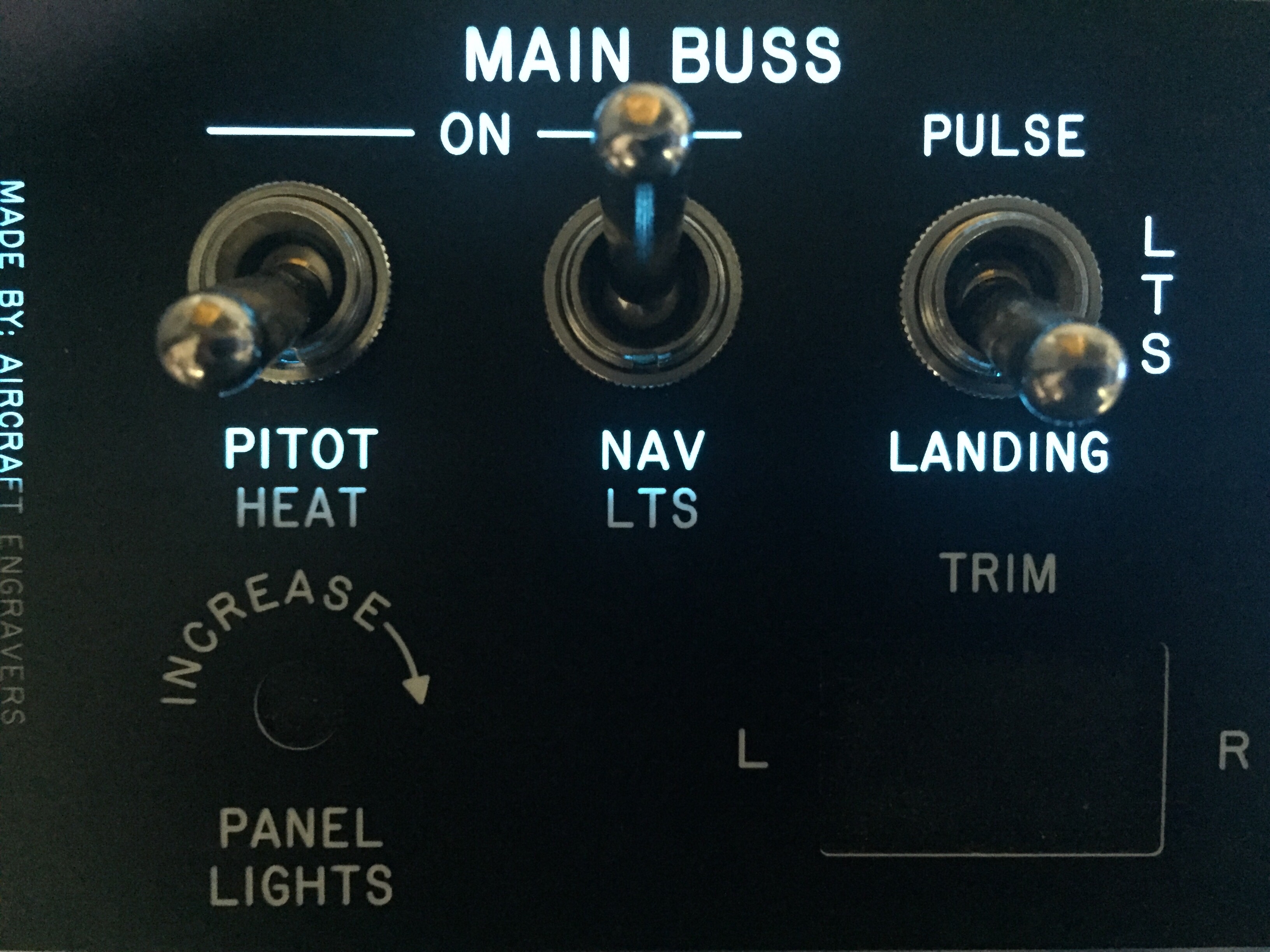
I also ordered a four channel dimmer from Pilot Lights to replace the three single channel dimmers for the overhead panel.  They all would fit up there, as space is tight, so this was  a good solution.  I’ll have a spare channel if I want to add anything later.  I chose to epoxy the mounts to the overhead cabin top which kept some of the wiring runs short.  All wiring for the overhead will be coming up through the center post from the sub panel.  I went ahead and fabbed up the wires for the switches and controls on the overhead so I could ensure it would all fit within the post – no issues there.  With that bit done, I was able to close up the overhead console minus the switch panel which is waiting on the back light panel.

Oh yeah, I sanded more on the doors.  You know, the same thing I’ve been doing for months now.  Gah, the damn things are never going to be done.

The art of design

If you aren’t building, you probably don’t care about this article regarding how and why I laid out my instrument panel the way I did.  For those of you that are building, be my guest and read on.

I have spent many Air Ventures looking and playing with avionics and decided some time ago that AFS was my favorite.  I don’t have anything against others, but the layout, functionality, and features of the AFS just fit perfectly for me and my flying mission.  I’m going to fly a lot of IFR with my airplane, as I already do with the Diamond so want a very capable suite of avionics up front.  I also don’t want to upgrade or add on for a very long time so I budgeted to do everything I wanted upfront.

A quick run down of the panel includes:

Two 10″ PFD touch screens

One 12″ MFD touch screen

Dual ADAHRS

IFD 540

Garmin G5 as backup instrument

XM radio and WX

ADSB in and out

Oxygen control head for MH 4iP

A/C control head

Space for SDS control head

Toggle switches and rheostats all matching

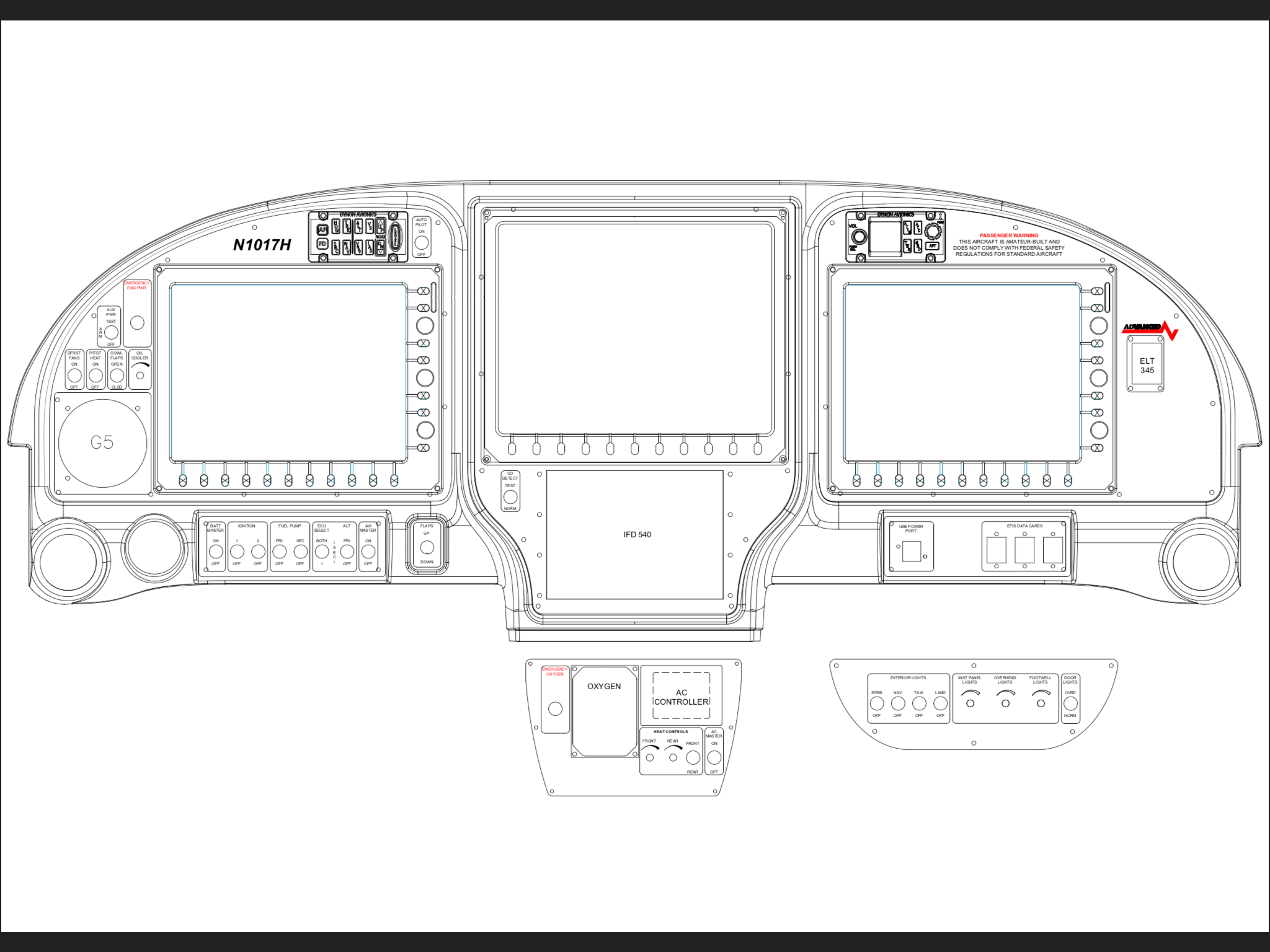
All controls that I need located to the left of the center console – no reaching over my pax!  Now, my wife is not a pilot and doesn’t really need the PFD in front of her, but we both like her to be situationally aware and I fly with other buddies that will appreciate a PFD on their side.  It also allows me to one day teach someone else to fly easier.  Again, I don’t want to have to put the airplane down for an upgrade later.  Do it right the first time.

The big pieces go in rather quickly as there aren’t many options of where to put them.  My main concerns were what switches go where and how to get a good flow on the order of switch groupings.  I also was determined to create a back light setup for the switches much like Ed Krantz did on his plane.  More on this later.

With the main components located, I decided on all lighting switches and dimmers to be located on the overhead console.  The upper left has the “misfit” switches like defrost, pitot heat, oil cooler, etc.  The main switch panel in front of me will have master switches and all engine controls in order of startup procedures.  Finally, the lower console will have the O2 and cabin climate controls where either left or right seat occupant can easily control them.

The space for the SDS control head is not ideal, but that instrument, should I go with SDS, is really only used during testing and tuning.  The EFIS will display all engine parameters for normal operations and I haven’t even decided if I’ll mount the display on the panel or remote mount it for use only when I need it.

I do a lot of night flying and despise red dome lights or using a flashlight.  While all three screens and the GPS will put out a good amount of ambient glow, I wanted the switches to be properly backlit to add that extra pop to the panel.  While playing around on the internet looking for lighting solutions, I came across electroluminecsent or EL panels.  They are a really neat product, only about 1/32″ thick and available in many different sizes which are then trimmable with a few restrictions.  All run off of a 12V transformer and provide equal, dimmable, light across the entire surface.  Perfect for what I was wanting!

I ordered a test piece to experiment with in the shop and requested a sample of engraved acrylic from Aircraft Engravers.  Match made in heaven.  The EL panel glows nicely through the laser engraved markings and can be cut, trimmed, and hole punched for all of the switches and dimmers that need to go into the panels.  The transformer makes a bit of high pitch whine, but it will be drowned out in the airplane and a few flight tests in the Diamond confirmed that the transformer was not electronically noisy, only audibly so.

With a successful experiment, I set back to work in Draftsight to come up with templates to be cut and engraved by Aircraft Engravers.  AFS, who is building my panel, will still cut, paint, and label the four main panels.  This will be a presentable back up in case my EL project doesn’t work out in the long run.  I worked with an EL supplier from Etsy who has been awesome to get a proper prototype panel cut for the overhead console.  There are some limitations with the EL panels such as the power lead locations and two edges that have the contacts running along them not being able to be cut.  It was a bit of puzzle work, but in the end fairly simple to draft up and layout.  Aircraft Engravers cut and engraved the acrylic overlay for the overhead console panel and I was able to put it all together with switches to see how it looked.

I was so excited that I forget to specify which color, so Marc sent white.  No worries, as the production version will be a blue.  Needless to say, I spent a lot of time sitting in the dark garage flipping switches that weren’t wired to anything!  It’s a very elegant solution and a rather easy one at that.  For the whole cockpit, all EL panels will be wired together with one transformer and be dimmable through a rheostat.  I wanted all of the instrument panel to match, so I’ll be spending some extra money on acrylic overlays for the entire panel rather than just smaller panels around the switches, but it’s my plane and I’ll do what I want to!  Wayne at Aircraft Engravers has been great and is pretty excited at this working so well, as he may be offering more panels like this in the future.

So now, I have finalized the lighting panels and overlay panels for production.  I’m hoping the avionics arrive on time at the end of February for me to finish wiring and installing.  With my higher level of customization, I’m not using the AFS quick panel switches so I’ll have a bit more work to do than most quick panel customers.  I’m very grateful to Rob, Stephan, and all of AFS for hanging in there with me on this over the top instrument panel.  In the end, I’m confident I’ll have a real show stopper that I’ll be admiring for decades to come.

I love shiny things

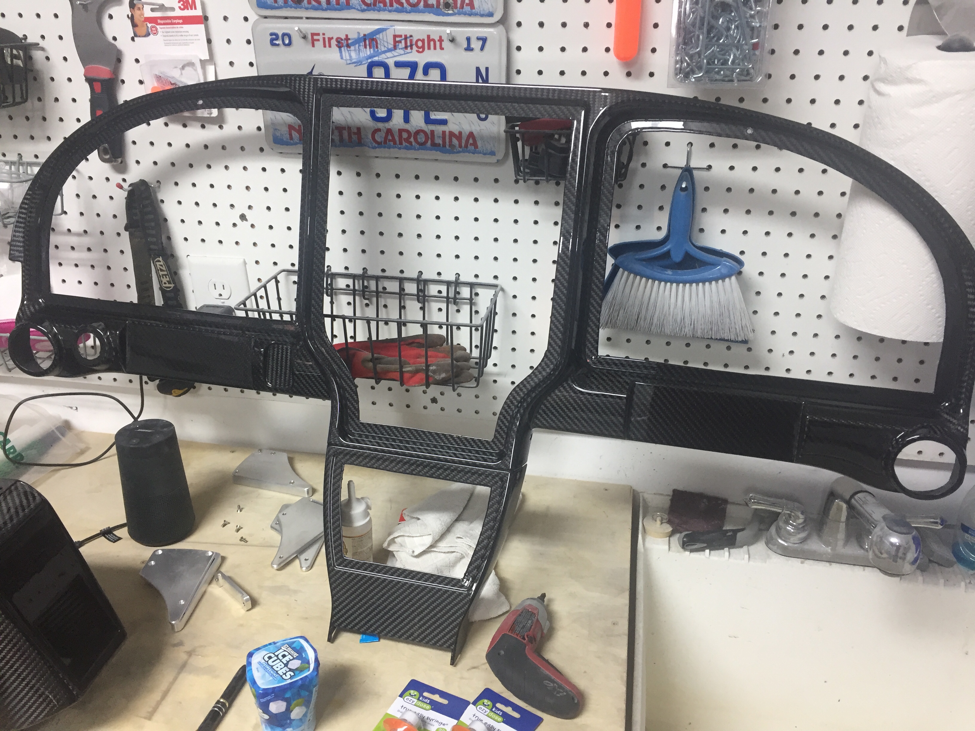
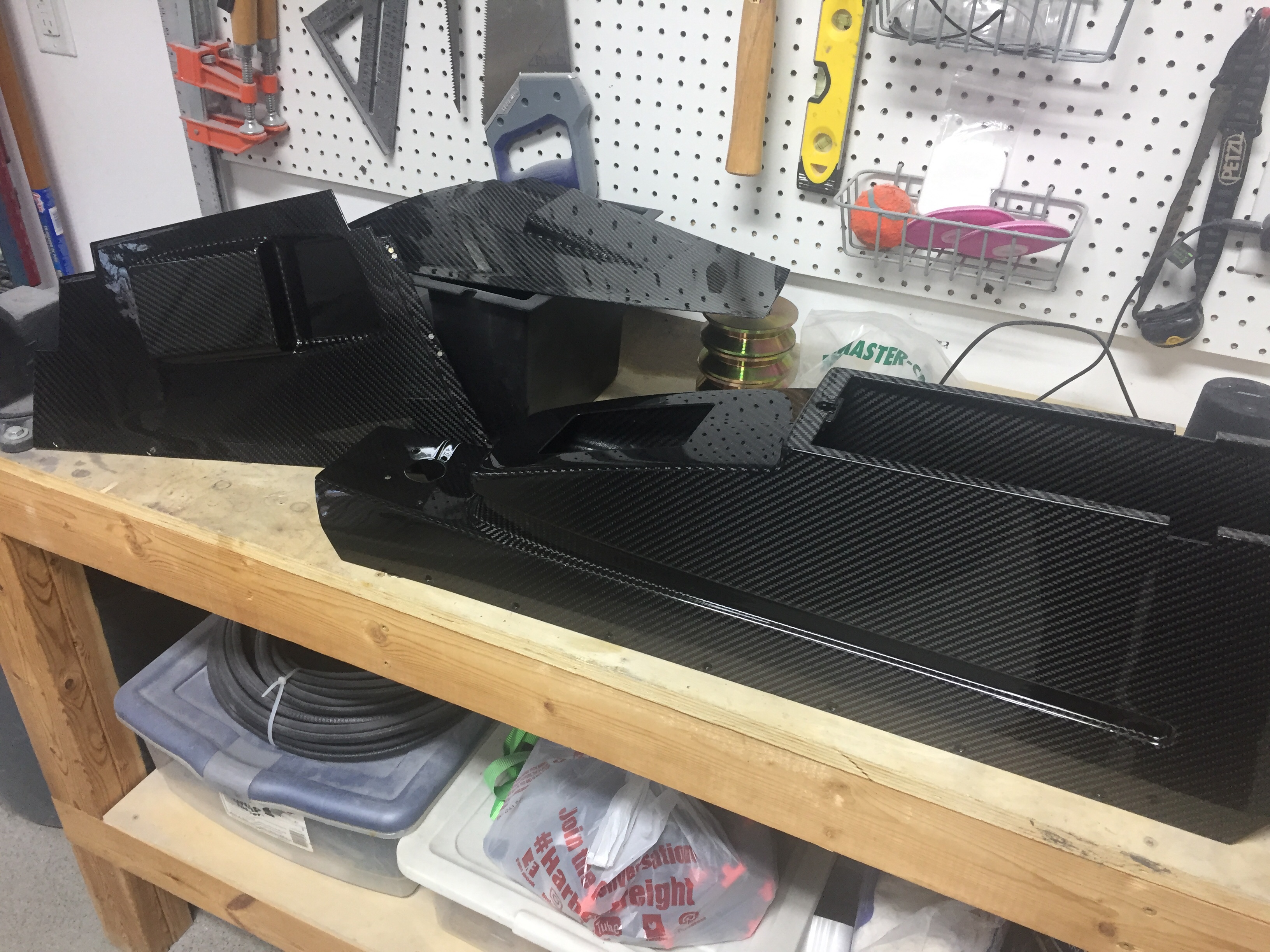
While the doors were being worked, I picked up the carbon fiber parts that were at the painters getting clear coat sprayed.  I was smiling ear to ear walking out to the car with them.  The pieces turned out better than I had imagined and are darn near perfect.  The painter put two coats and while it has a nice gloss reflection, it’s not overly shiny.  The carbon really comes to life with the clear over it and I think it’s going to look great in the cabin.  I now regret painting the overhead instead of clearing it.  I have made up my mind if I ever have issues with the paint on the overhead, I’ll strip it and clear the carbon portion without a second thought.

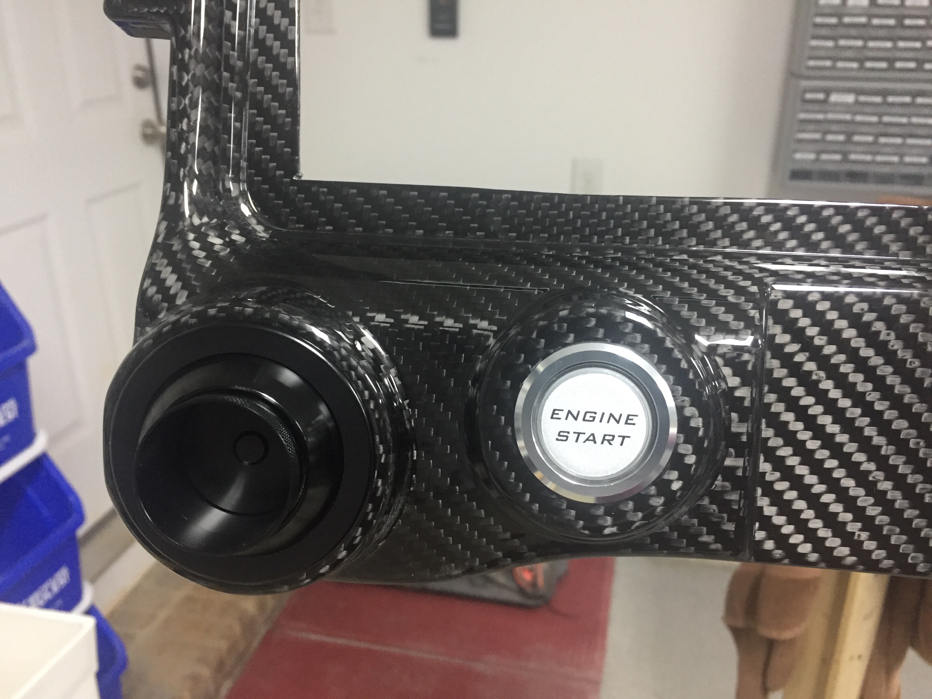
At home, I had to put the push to start button and Aero Vents in to see how it looked and make airplane noises.  Some hours later, I got back to work printed out a few panels to see how things were going to fit and look.  I’ve been working for over a year on my instrument panel layout, playing with this and that, moving things around, and finessing the position of switches, etc.

I started with Panel Planner and really liked it for the ease and simplicity of it.  It is great at putting components in the panel and seeing what it will look like with all the fancy touch screens everywhere.  What it’s not good at is custom anything.  I never could figure out proper switch labels and the 310 switch panels weren’t loaded into the panel template, so I just stuck with the main layout on there.

Meanwhile, I reached out to Rob Hickman at Advance Flight Systems (Dynon) with a few technical questions about the AFS system.  We had a couple great conversations that led to him providing a quote for a “quick panel” customized to my liking.  Surprisingly, he was able to quote a complete panel far less than just the components from Stein!  I had planned on doing all of my own wiring, but I couldn’t pass up this opportunity and deal, saving me money and time.  I started working with Stephan on the layout and wound up using Draftsight Plus at his recommendation to do more detailed drawing on the layout.  I decided to give poor Stephan a break and finish the final details myself as it was just easier and I’m a control hog.  Draftsight is based on a version of Autocad that I used back in high school so I was able to pick it up really quickly.  It’s also much easier and simpler than SolidWorks, as I don’t need computational fluid dynamics to label the Defrost Fans switch and put borders around switches.

The switch panels, upper, and lower console panels turned out great and were a good fit.  I was able to confirm the lack of need to reach across the center console for anything I’ll need in the cockpit except for activating the ELT, a major goal that I wanted after flying the DA-40 and constantly using my right-seater’s knee as a armrest.  Since I had already ordered the Apem toggle switches and Pilot Lights dimmers, I decided to mock up the overhead panel to finish the night off with more flow work and airplane noises.  I admit I’m pretty giddy about getting controls in the cockpit and I’m really happy with how they layout is working.  I can’t wait to get the panel and avionics from AFS installed to light everything up!

Back to heavy metal work

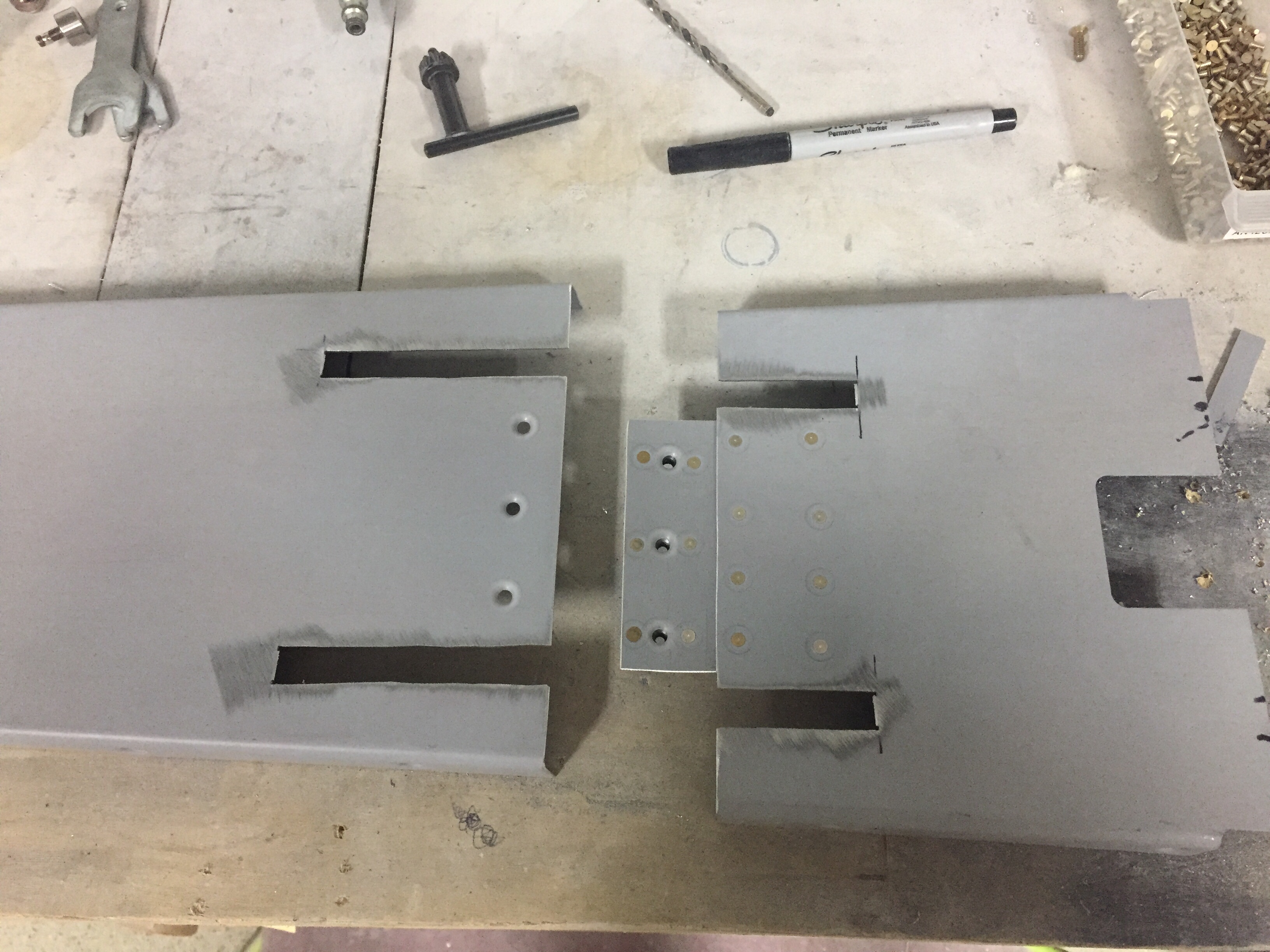
One task that I want to document for others I forgot to mention is modifying the tunnel cover around the Control Approach rudder pedals.  The cable attach arms are relocated inside the tunnel so slots need to be cut for them to move freely in the cover.  I measured their arc and marked the tunnel cover where I wanted to split it into two pieces.  Before cutting, I marked and drilled a center plate to hold nut plates which will allow me to screw the two pieces back together.  It was a pretty simple modification as was cutting the slots for the arms in each piece.  Again, I’m trying to consider maintenance and access down the road as much as I can.

I also took the time to modify the seat rails since I got the Aerosport seat levers.  Others have described this mod and it makes removal of the seats a snap.  Step one is to remove the delrin guides from the seat bottoms and trim the first 1 ½” off followed by reinstalling them.  This allows the seat to be slide rearward on the rails and then tilted around the flap tube cover with the necessary clearance.  I then removed the aft rail stop and drilled through the rail into the plate below.  Installing nut plates below the plates lets you put bolts in place of the screw and nut on the stop.  Now, I can get to the bolts from the top down eliminating the need to reach under the seat plate to get the lock off, allowing the seat to slide freely rearward.  It all makes sense when you look at it.

I’m trying to knock out some little side tasks along the way now in the spare time.  I used some excess epoxy from a door filling session to install the front vent NACA scoops.  I drilled a few holes and used clecos to hold them in place while the flox cured overnight.  I don’t have proseal and didn’t want to use any silicone on the area since it will be painted.  With minimal flexing and a good scuffing on both surfaces, I am confident the epoxy will hold these just fine long term.  The scat tube will have a short run from there to the Aerosport vents that I installed in the instrument panel.

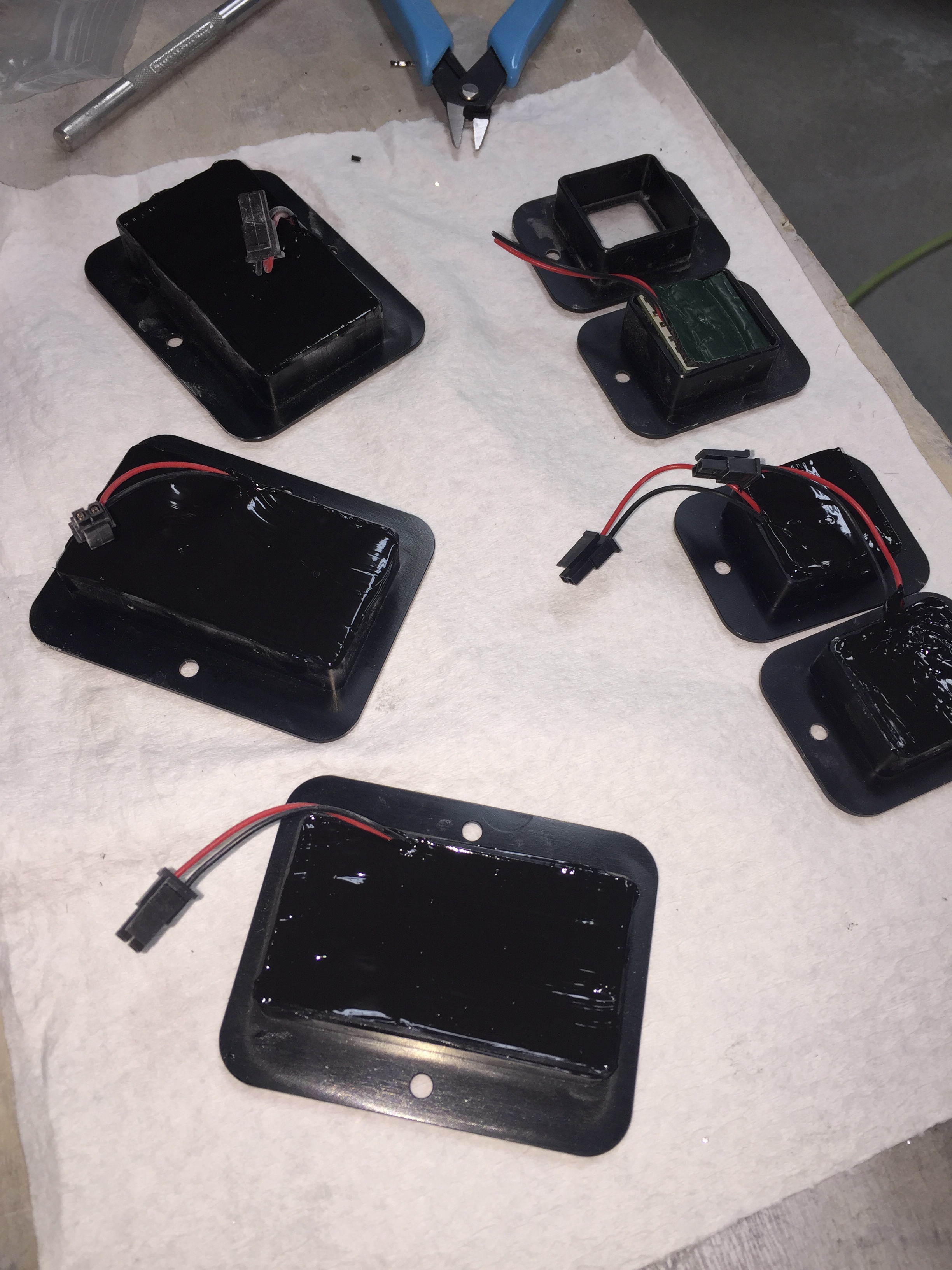
I also performed a quasi service bulletin from Sean at Plane Around.  When I received the lights from him for the overhead and doors, several had bad boards which he promptly replaced.  I got a call from him with an interesting finding.  He used a brass wire over a piece of foam to hold the LED boards inside the aluminum and plastic housing.  He found that in a few instances, the wire was touching the board and shorting out LEDs.  Awesome service!  He called and suggested using a different method such as silicone which is an easy solution.  I removed all of the installed lights and completed the rework after ensuring all LEDs checked good.  I took the opportunity to install the micro molex connectors on the remaining few assemblies as well.

Service bulletin complied with in accordance with published guidance, OPS check good!

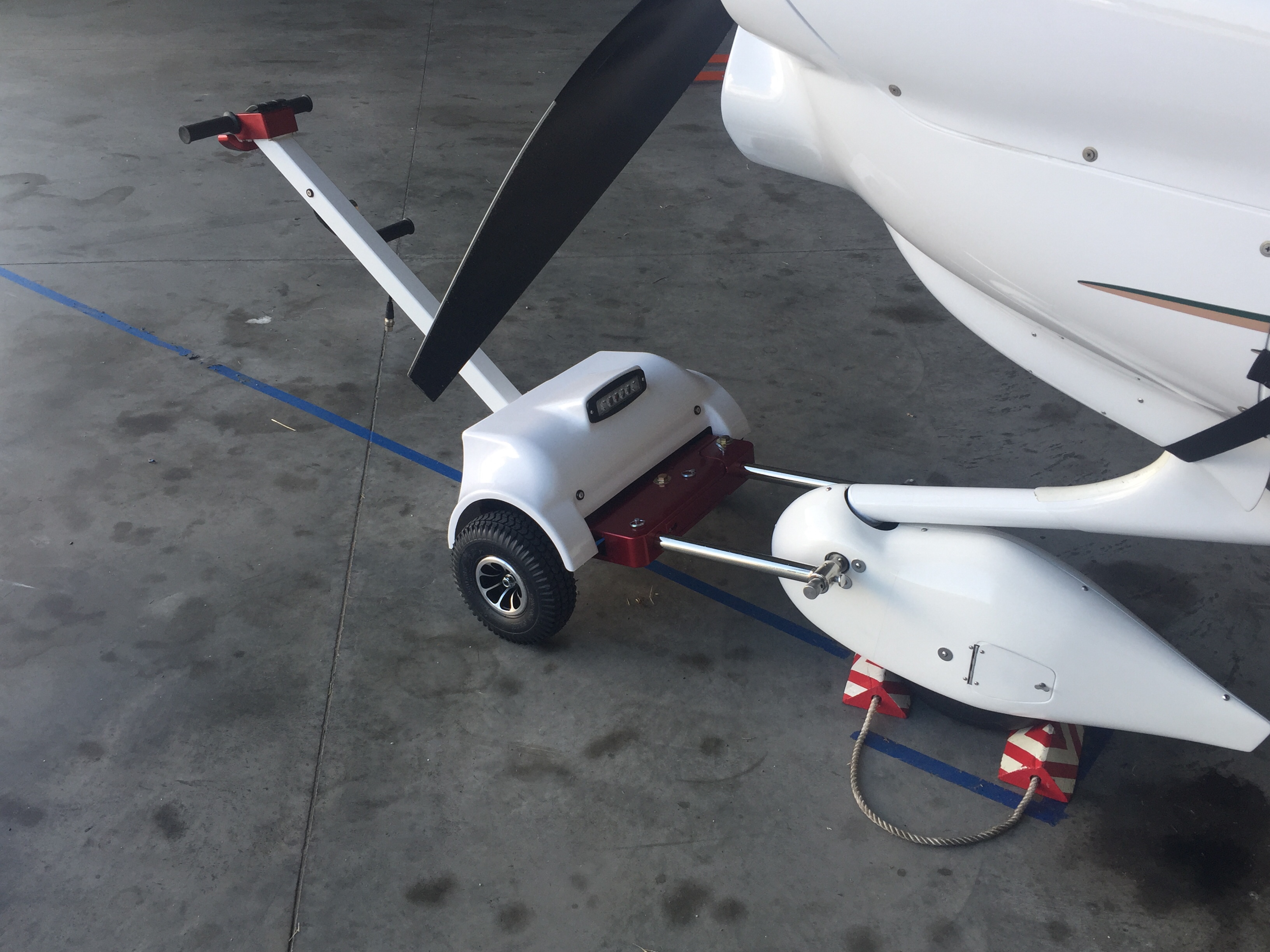
And finally, another cleanup item to mention was the addition to the hangar family.  While she hasn’t been officially named, our new Best Tugs Alpha 2 arrived!  I ordered this at OSH last year to use on the DA-40 we fly now and for long term with the RV.  It cost a pretty chunk of change (plastic, let’s be honest) but man is it nice.  It will save my twice-operated on back for years to come and is really handy to maneuver the airplane around.  It took a bit of practice one afternoon but now it’s just like pushing a shopping cart!  I requested the smooth cover with the intention of having it painted by Jonathan to match the RV but didn’t realize the red anodizing was going to arrive.  Oh well, not the end of the world.