Splash of color and an Oops

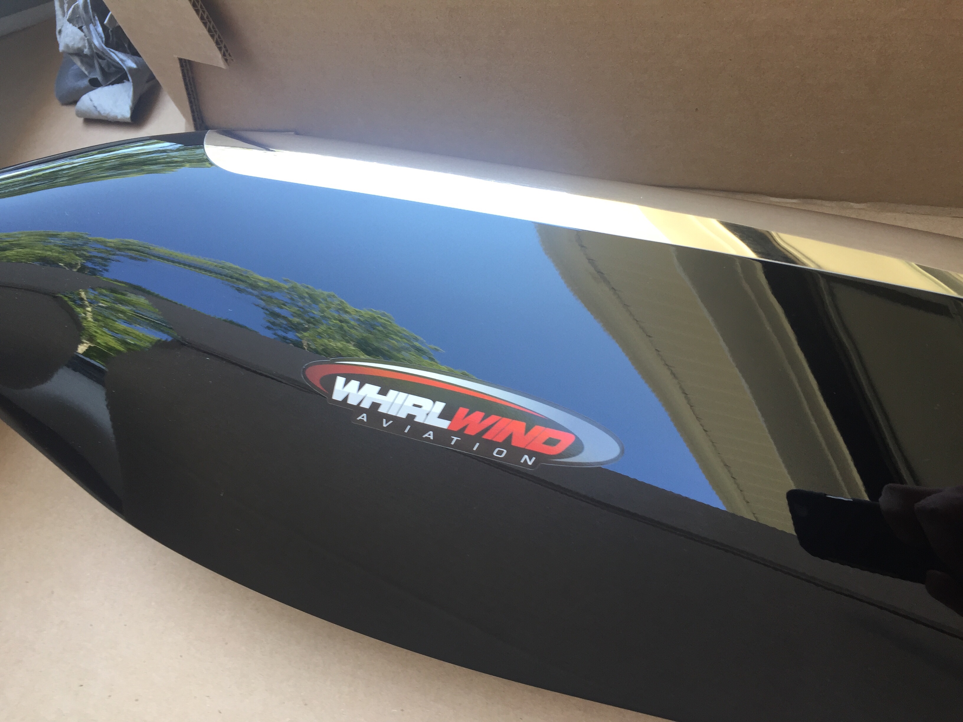
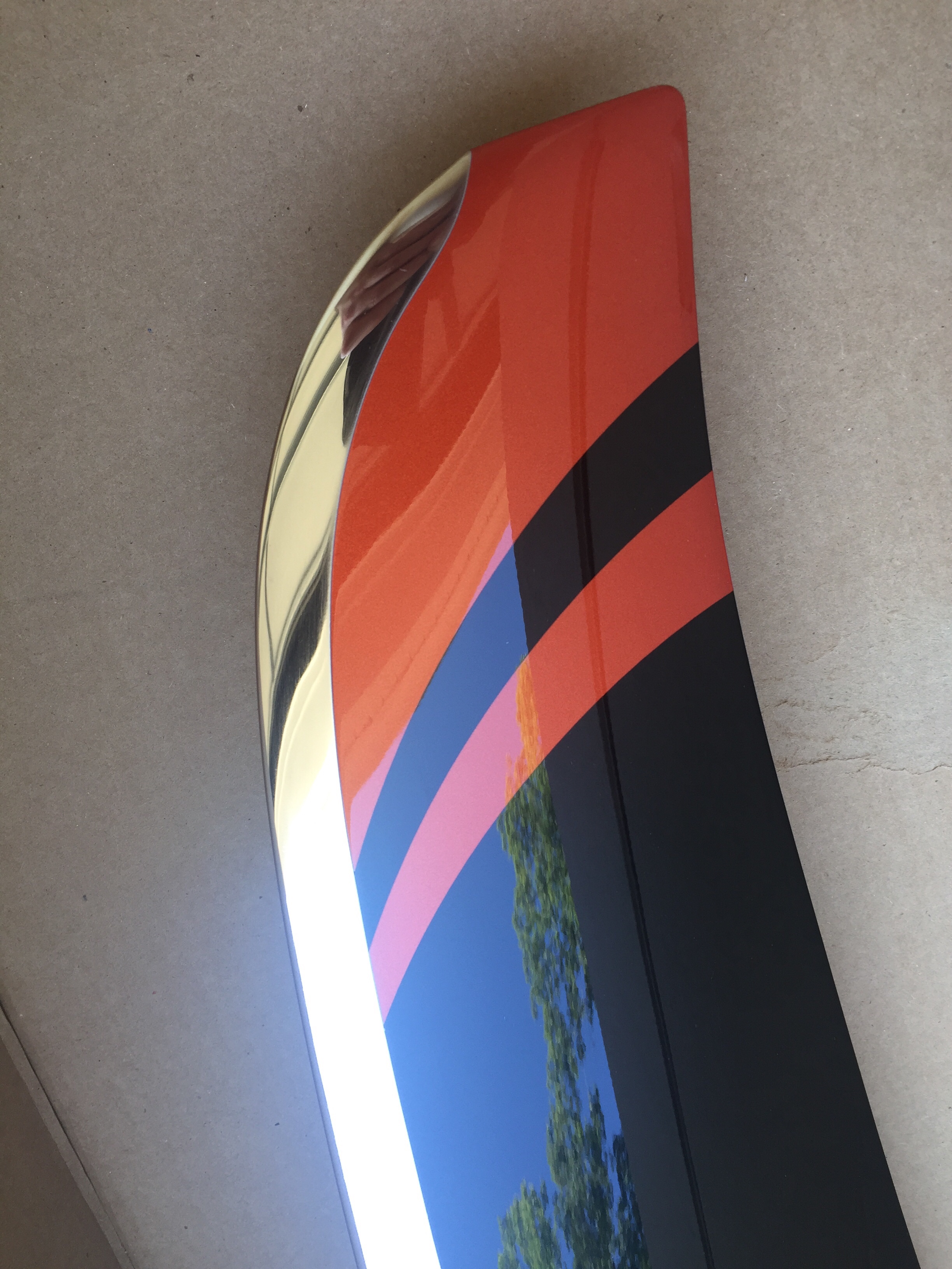
After returning from our trip up north, only a few days passed until we received a big package with a piece of art inside.  Our (second) propeller has arrived!  Whirl Wind delivered about a week late, but with prior coordination and communication with me so I was super excited to see what it looked like.  As chronicled earlier in the build, I purchased a propeller but decided to sell it instead of it hanging on the wall for three years before I was ready for it.  Joe Keys, you can’t have this one.  I knew I wanted another WW and the HRT blade is now a refined blade profile and is simply stunning.  Our orange was color matched and looks great with the black and nickel leading edge.  For now, the prop will go to a friend’s hangar to hang out with the wings until we move to the airport.
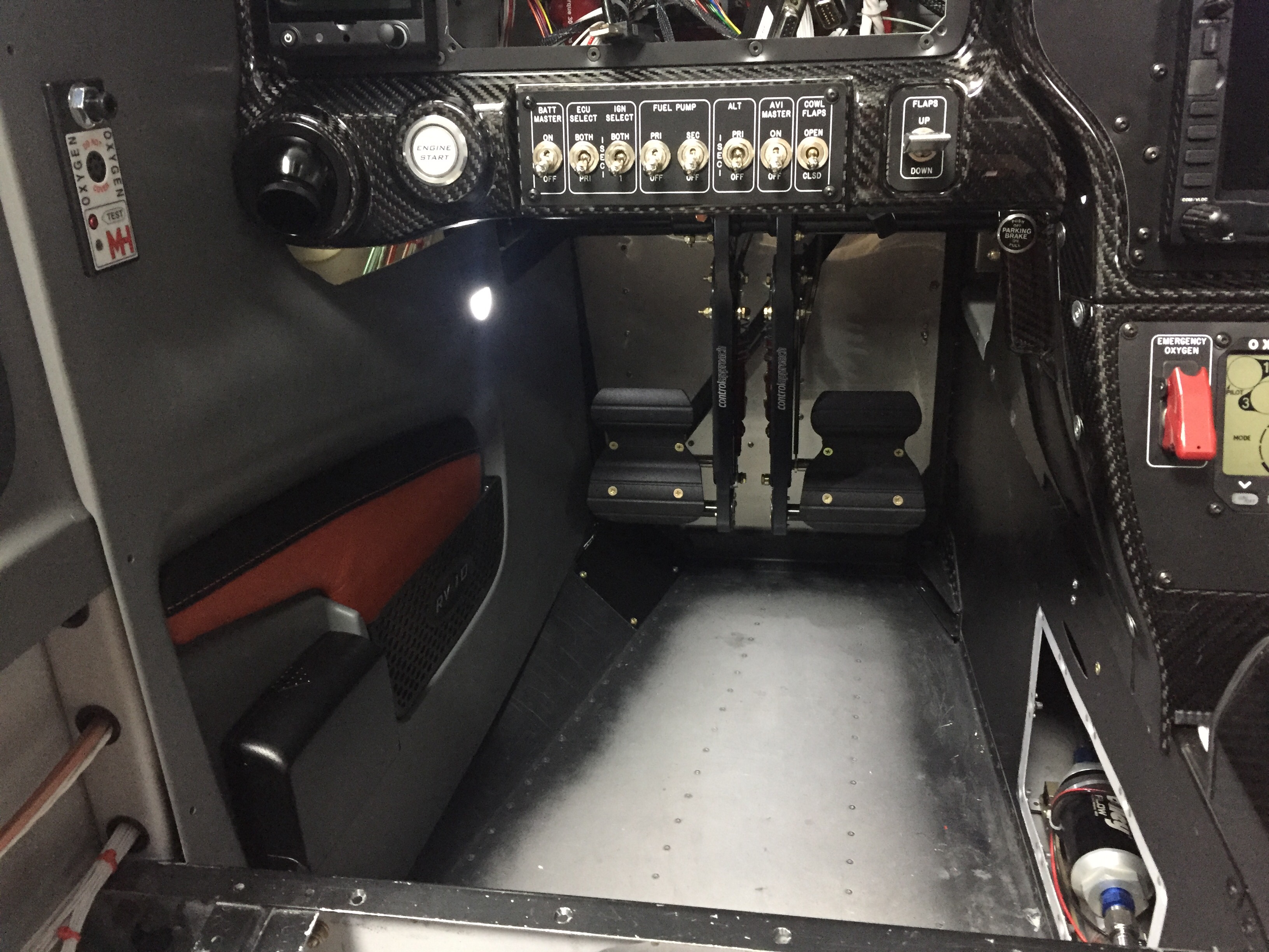
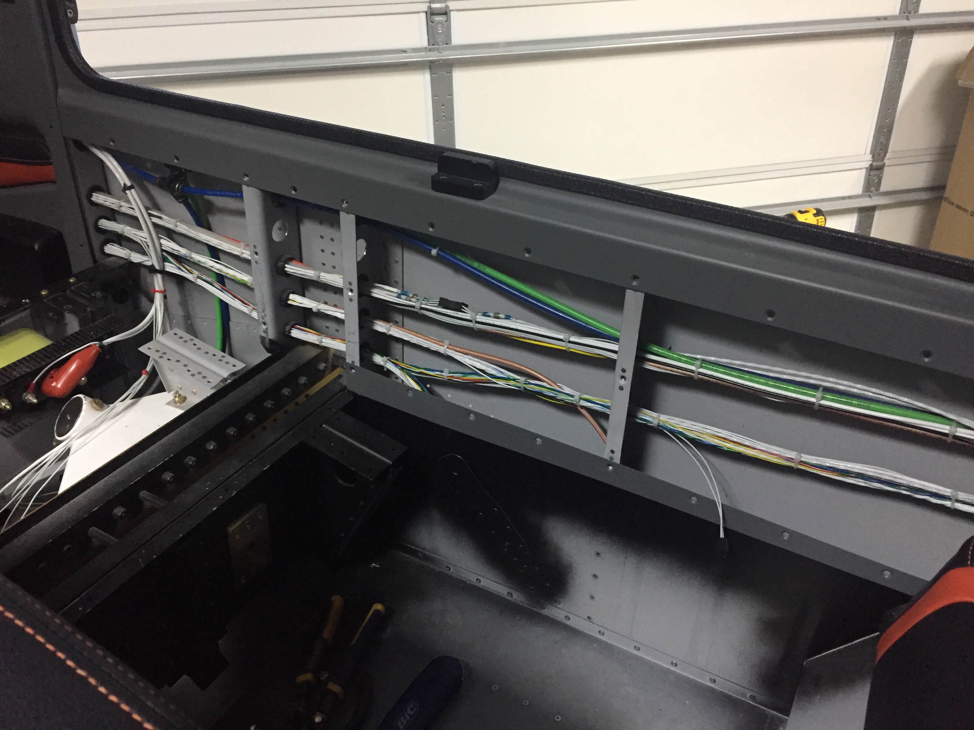
Adding even more color, I finished up the last of the wire bundling on the cabin sidewalls and went ahead installing the side panels with leather inserts.  They had been trimmed and painted for some time but I held off pulling them in and out until I knew I was done.  I spoke to Vic Syracuse who will be my DAR for airworthiness inspection prior to putting these in, as I wasn’t sure how open he wanted the airplane.  He advised to have it essentially flight ready except for rear pax tunnel cover (to inspect the elevator bell crank), cowling, and tunnel access panel.  This is the first time I’ve hooked up the foot well lights and I’m really pleased with the amount of light they give off.  It’s just enough for convenience while not quite enough to perform surgery on the floorboard.
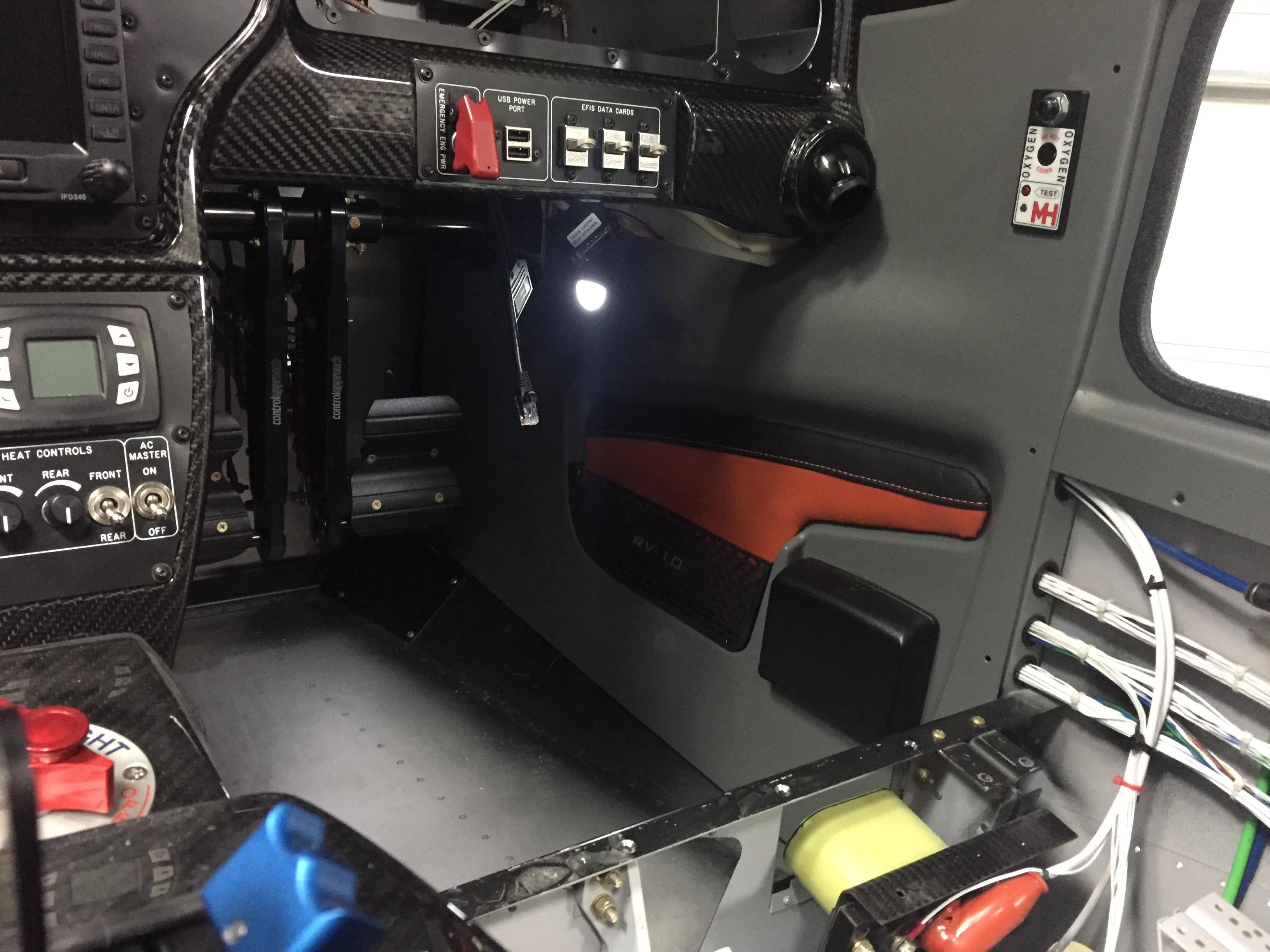
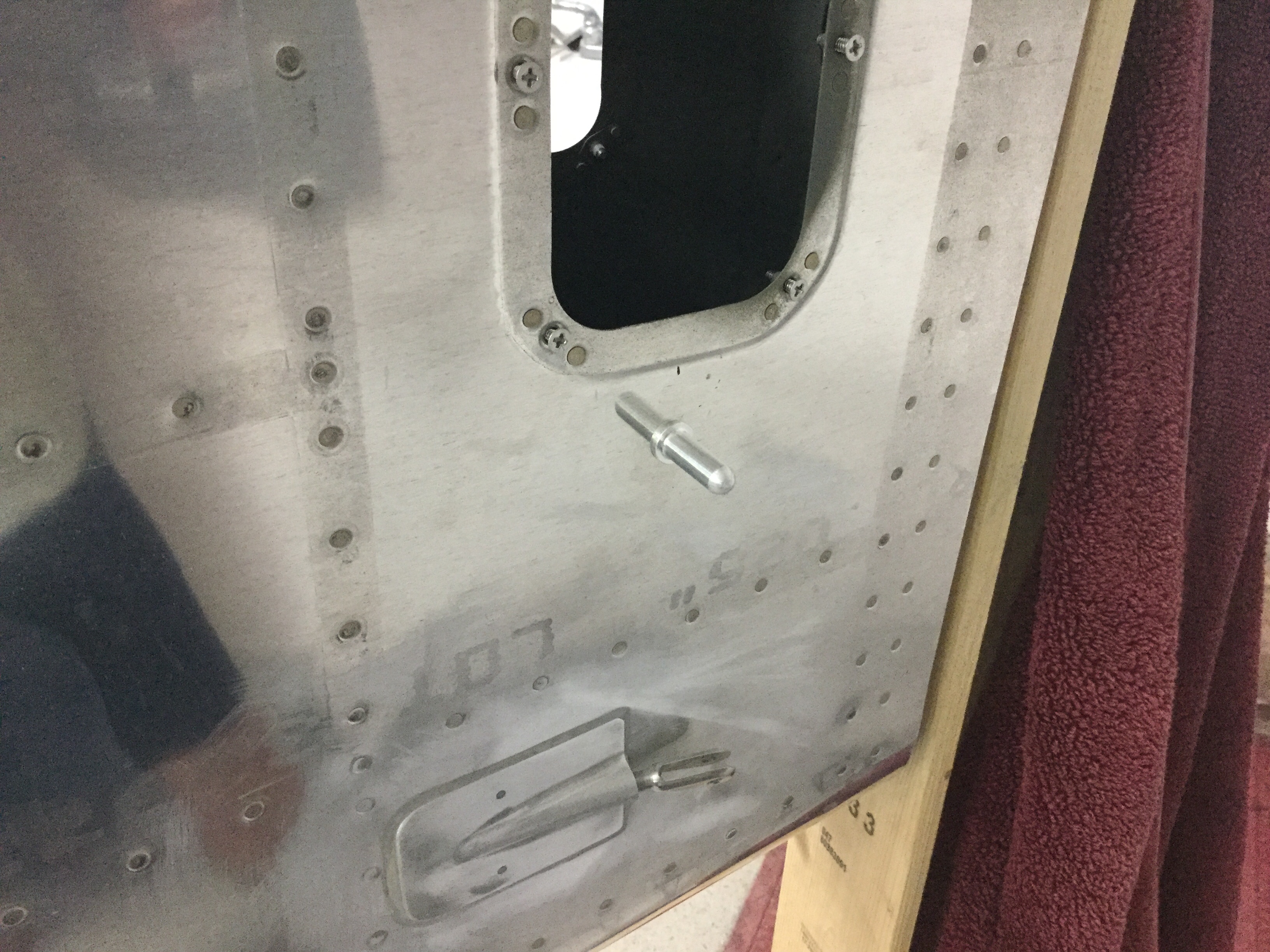
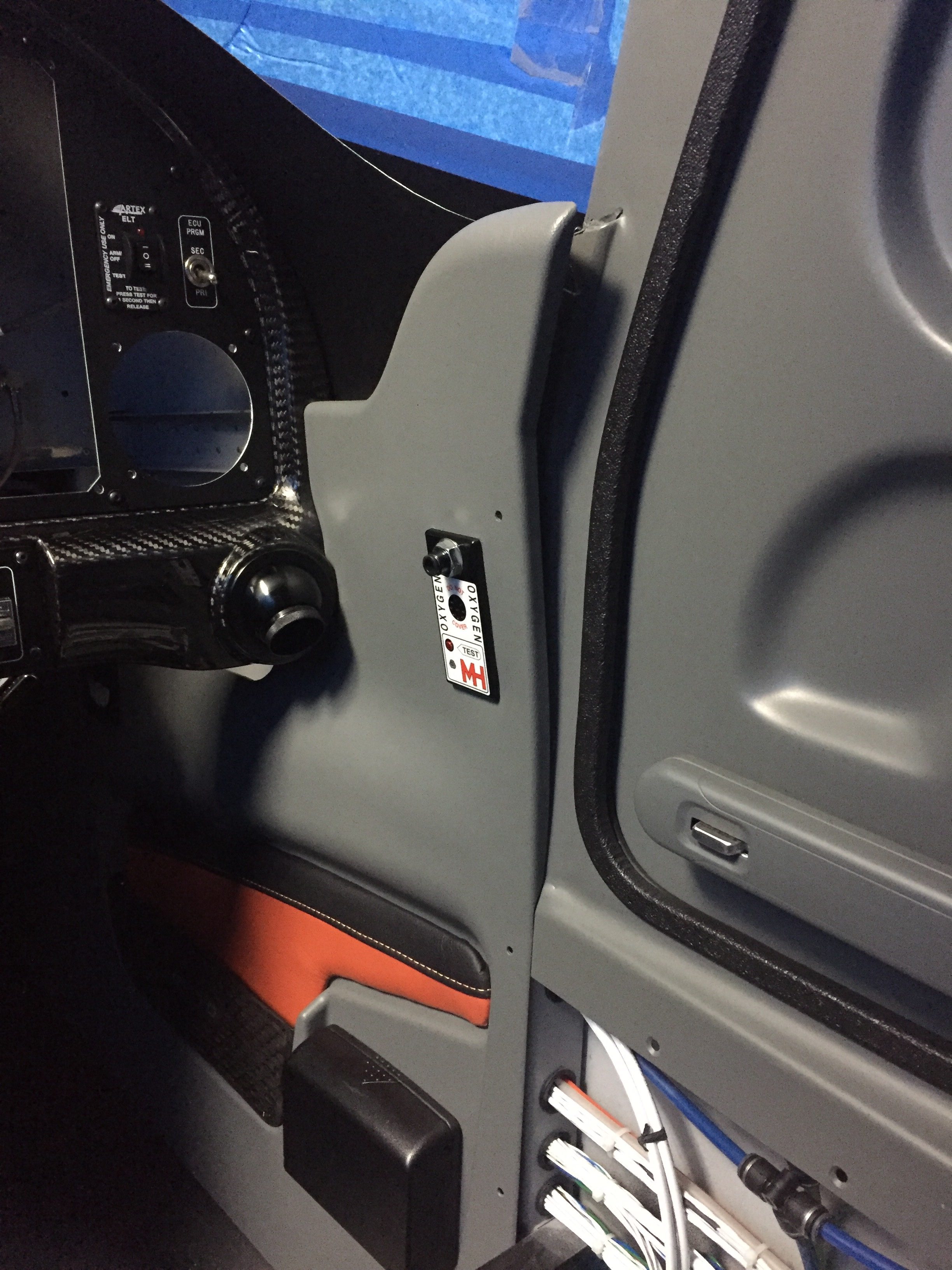
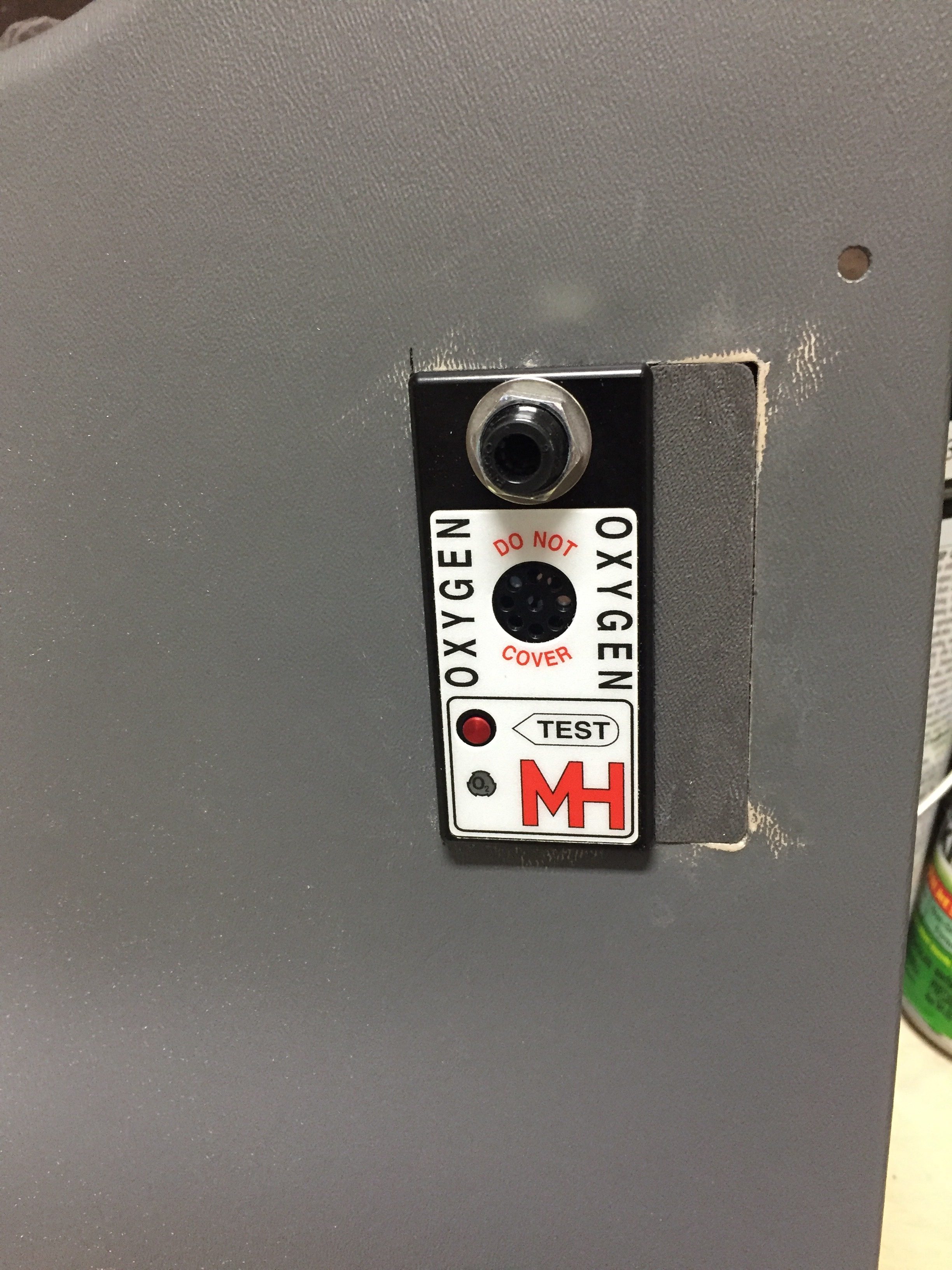
Unfortunately, not all of the gods were looking favorably upon this new addition and when I closed the door, the pins interfered with the oxygen ports, thus not allowing the doors to latch properly.  Turns out I have the ports ½” too close to the door frame.  Darn.  Well, I said, a lot more than that and maybe one or tools took flight across the garage with no lasting damage.  My blood pressure through the roof due to my ignorance and stupidity of not being mindful to this interference, I weighed the options of replacing $500 panels or coming up with a patch.  I can’t make the pins shorter since they wouldn’t function correctly with the Plane Around latch mechanism.  I had already had to glue a piece on the pilot side panel and reinforce it with a bit of epoxy.  The seam was easily hidden and paint covered everything, so I was hopeful I could repeat the process.  A call to Will at Aerosport Products equaled a few scrap pieces of plastic heading my way.  An evening of creating two patches and a bit of filler, and I’m back on track.  If you look close enough to tell the patch is there, you probably won’t be flying in my airplane again; kindly go away and take your judgement with you.
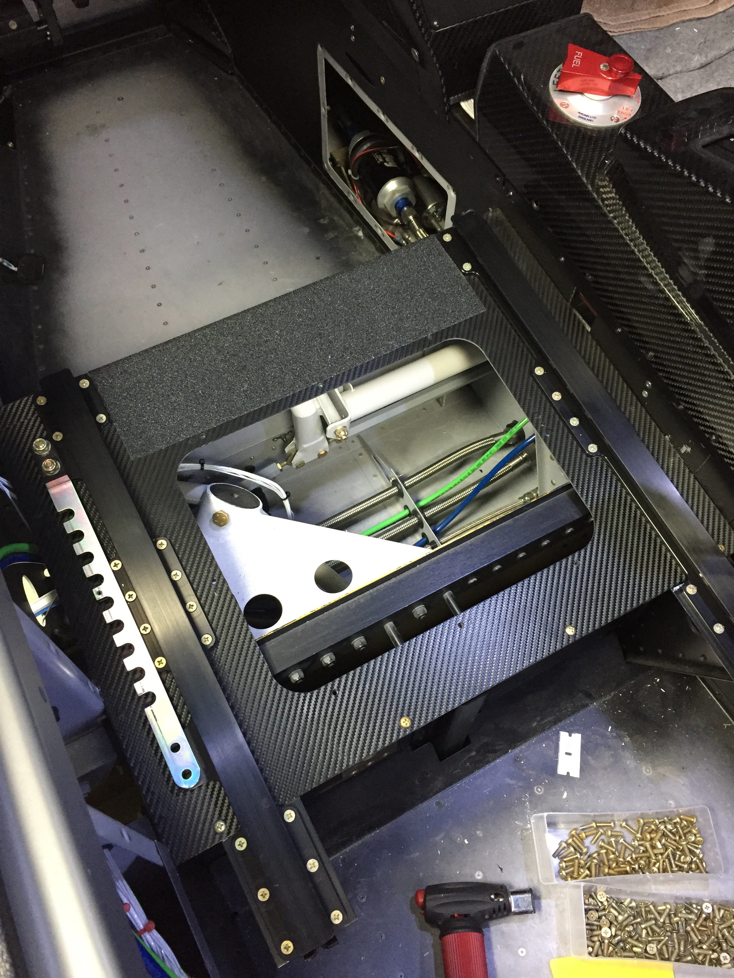
Meanwhile, I applied the 3M carbon vinyl wrap on the seat pans to clean those up.  I figured out quickly paint was not going to hold up there.  Brian and Brandi had great results with the wrap material, so I figured it’s worth a shot.  I then put a strip of anti-skid tape to facilitate stepping on the seat ledge while getting in and out.  It really cleaned up the area nicely.  I also shimmed the outboard pilot seat rail, as the bracket above the gear mount was a 1/8” proud causing the rail to bend when screwed in.  Not sure what happened there, but with a few washers underneath it’s nice and straight and secure.
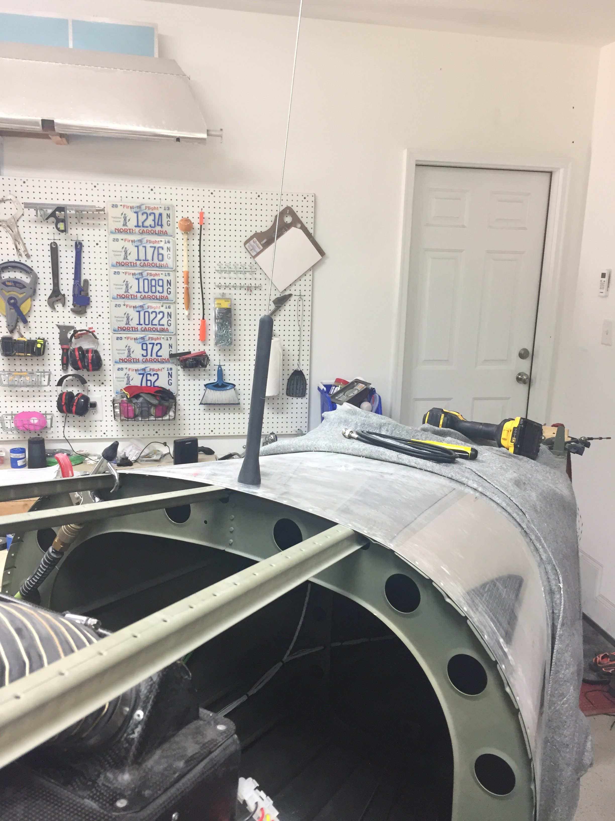
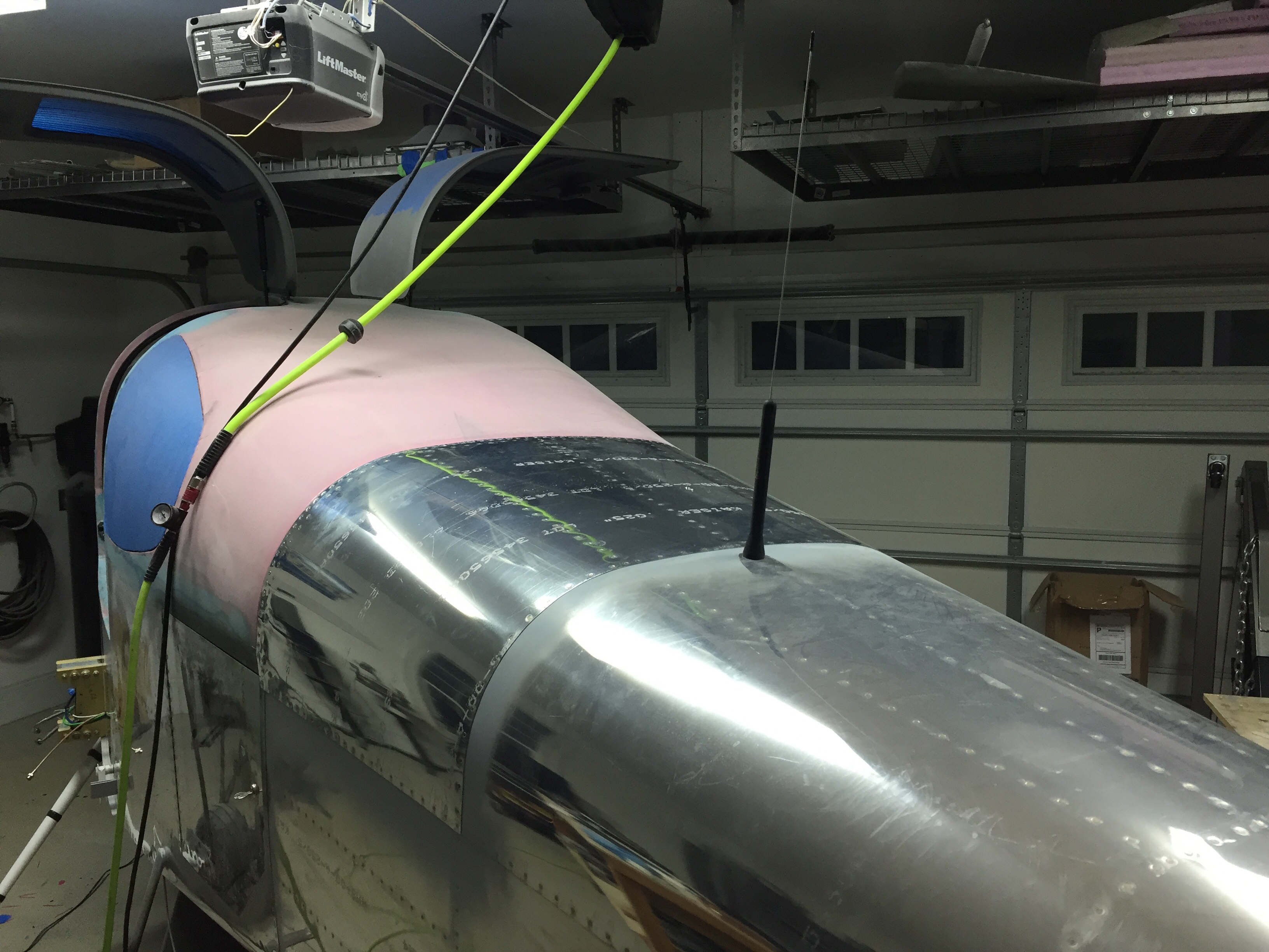
I quit trying to cheat the system and installed the ELT antenna on the top of the tail cone.  I tried every which way to hid that hideous monstrosity of an antenna but my conscious told me that it is probably the most important antenna on the airplane thus deserved its place per the install manual.  I’m sure it will grow on me.  The idea of burying it in the tail cone or tail fairing was tempting, but a talk with my DAR convinced me otherwise.
Continuing in the cabin, I spent an afternoon applying the headliner material to the fiberglass shells from Aerosport that had been trimmed for quite a while now.  It was a bit of a messy job with the spray adhesive, but not difficult at all.  I took my time and kept my fingers clean which resulted in a darn near perfect result.  After putting enough Velcro to hold a car upside down, the headliners slid into place and really dress up the cabin cover now.  The color matches great and was overall a lot easier than trying to smooth and paint the cabin top itself.
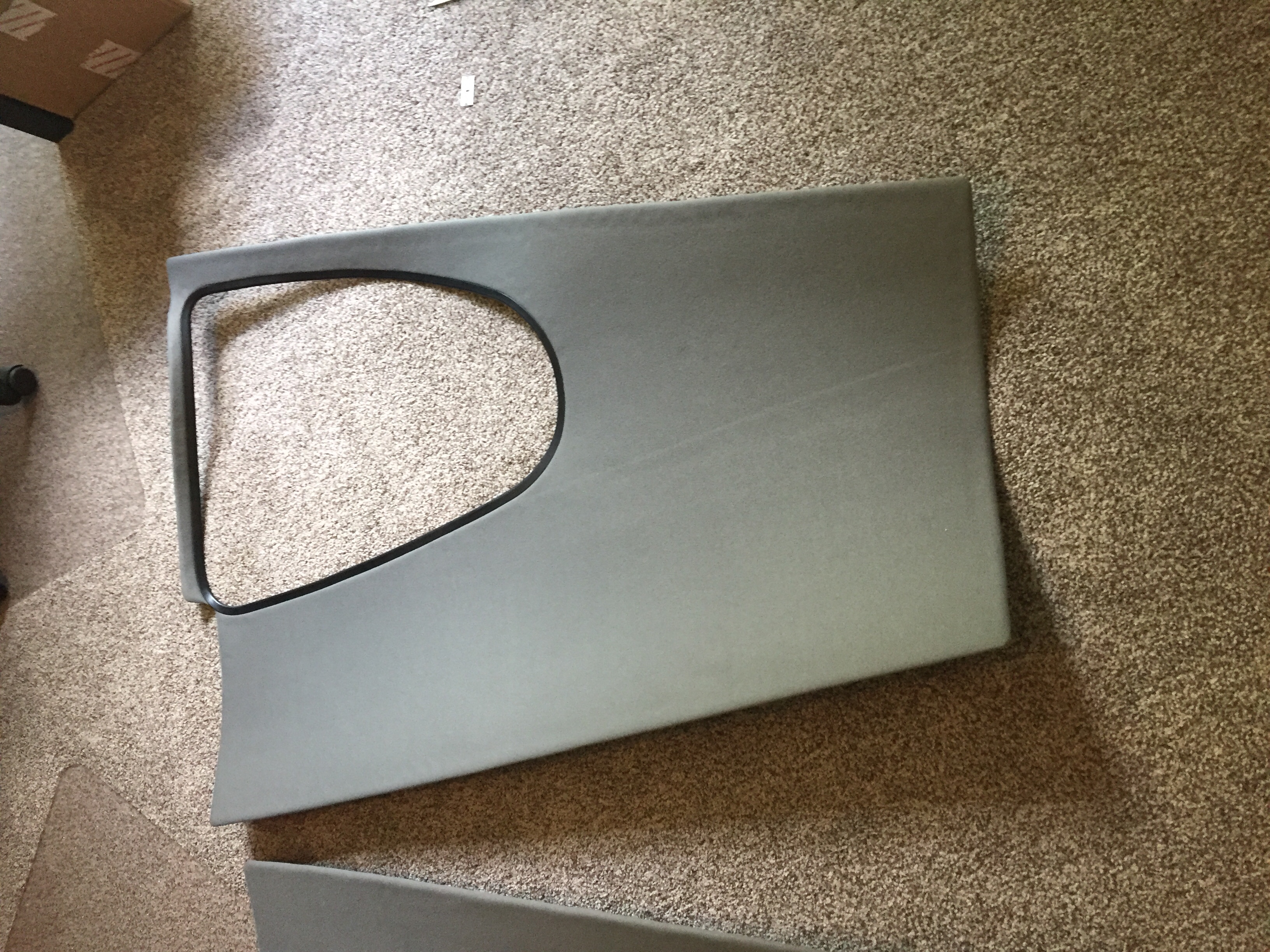
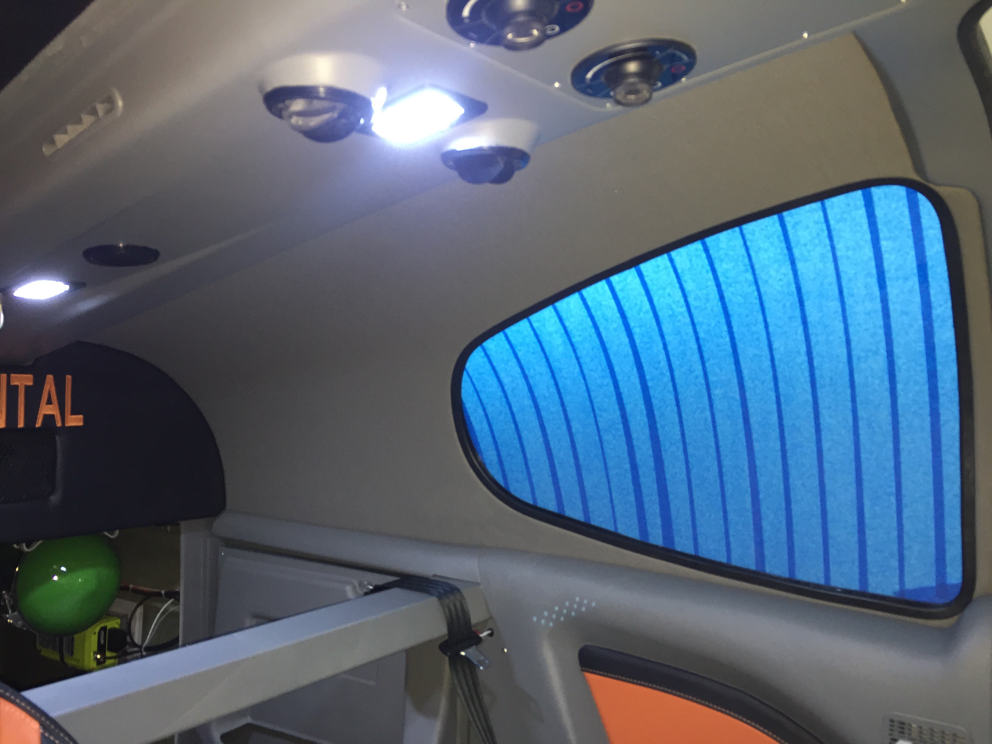
Finally, the rear bulkhead cover was back from Aerosport with the matching leather and embroidery.  I used Velcro to mount it to the bulkhead panel after installing a grill for the air conditioning return.  It turned out great and I’m really pleased with the fit and finish once it was all installed.  The cabin is really coming together with the rest of the rear side panels installed and inserts in place.  It’s tempting to put the carpet and seats in, but I’m holding off to keep them in good shape and clean while I finish building.
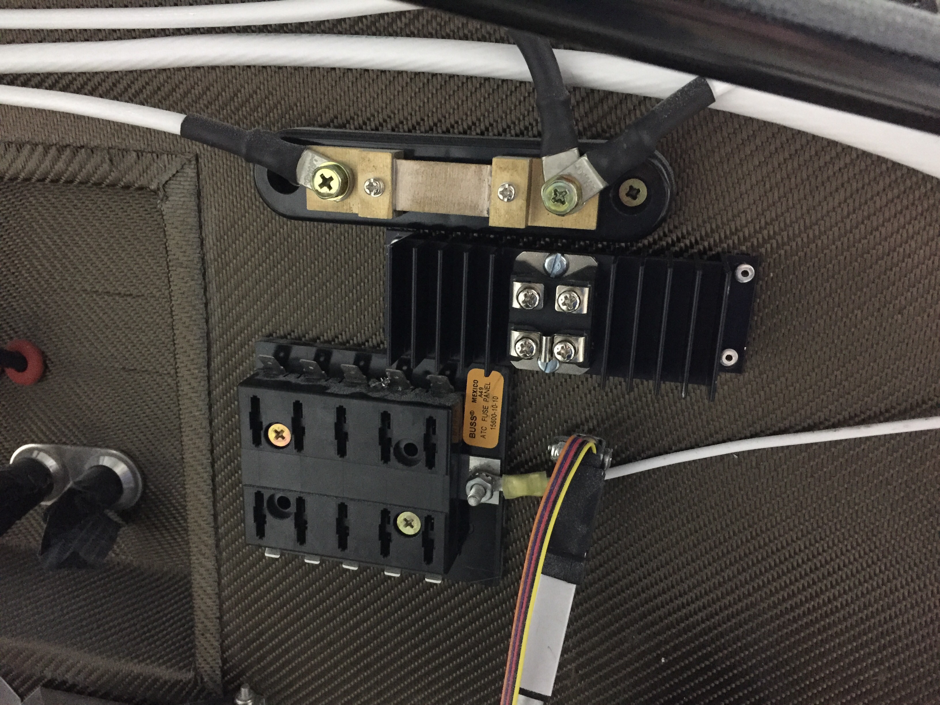
Upfront, I had an epiphany about my shotky diode and how it should be used to protect my engine bus.  The goal was to isolate the engine bus from the rest of the system such that I can turn the emergency power switch on (direct connection from battery to engine bus) and not have the electrons go to the man bus.  This essentially covers a short somewhere in the system or electrical fire behind the panel and gives me a bit of redundancy on keeping the electrically dependent engine going.  I wasn’t placing it on the proper power lead on the schematic, so it finally dawned on me it should go from the main power supply instead of the backup lead.  So, I installed it on the firewall and will work on a solid copper bar to hook everything up.
Punching the punch list

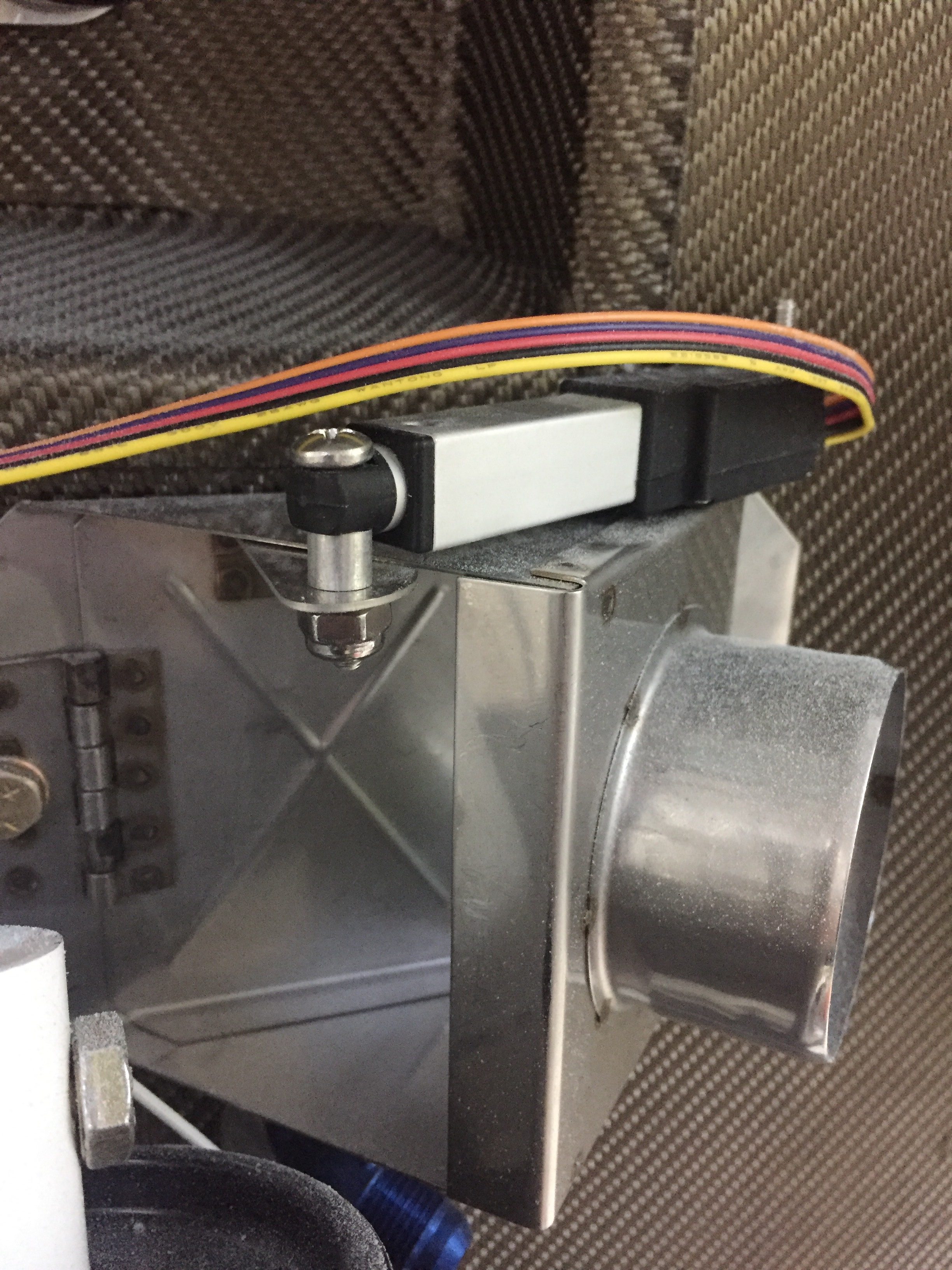
There are a lot of little jobs that go along with the big jobs on building a plane.  I’m trying to use my time efficiently while waiting on the engine to knock out a bunch of them.  The first was fixing the arms and servos on the heat ducts up front.  An order to ACS and a few minutes at the band saw and the servos for the heat and oil coolers were attached properly and pots adjusted for full travel.  I also spent an hour trouble shooting a bad pot for the rear heat duct, as I have a switch that allows either the front or rear rheostats to control the servo and the rear rheostat was inop.

I cussed and bled in equal amounts installing the last of the seat rail brackets now the gears are on.  The nuts and bolts are not easy to access at this point, but you have to wait in order to install the gear bolt.  I also put in the last bolt and custom spacer for the GPU plug which helps reinforce the receptacle by attaching it to the seat pan.

I ignorantly forgot to install the transponder antenna before buttoning up the tunnel, so I had to take the center console, tunnel cover, and lower instrument panel off to get down in there.  Of course I burried it near the core of the earth which made access tricky to say the least.  I was able to squeez my hands down there and got it all bolted on with the coax attached.  I knew I had left one fuel line untorqued but couldn’t remember which one so checked all fuel line fittings for proper torque.

The last task in the rear tunnel is to secure the aircon lines which I did with some hose clamps and edge grommet material.  Again, not fun to get to the hardware but it was doable and will rarely if ever be removed.  The lines are now secure and fit nicely in the tunnel, I’m glad I didn’t run them down the side of the fuse.  I also secured the last little sections of the O2 lines in the tunnel.

My ELT antenna placement has been a topic of disagreement on VAF, as I really wanted to avoid mounting it on top of the tail cone.  It’s big, ugly, and ugly.  Mainly, though, it’s ugly.  It’s also essential to my life and the lives of my passengers should the worst happen and we have an accident, so I guess it’s important to do it right.  I debated on doing some reception tests with it mounted internal to the tail cone, but honestly, I just got lazy and decided it really isn’t that ugly.  In the end, I chose to do it the right way and put it on the top of the tail cone.  The cable was secured along a bulkhead and the last of the wiring clean up for the O2 tank / ELT was completed.

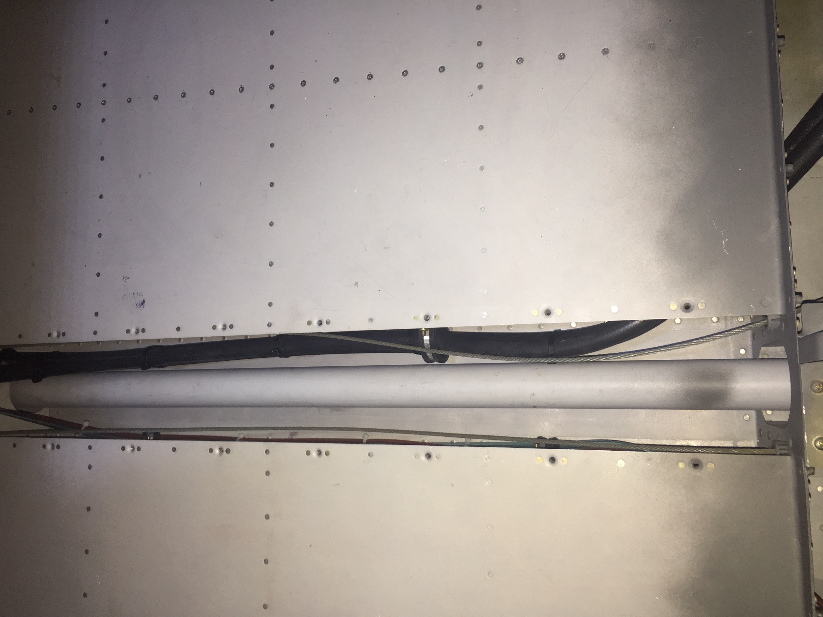
I love spending time wiggling back into the tail coffin, I mean cone, so I made a fort with blankets and towels and dove in to attach the OAT sensors to the ADAHRS and finish securing tail cone wiring.  I put the OAT sensors below the access panels underneath the horizontal stab since I had all of my wing wiring complete and for shorter wire runs to the ADAHRS.  Since they have to be calibrated anyway, I’m not too concerned with exhaust from the engine affecting them too much.

The O2 tank was put back in for good and connected to all of the lines.  I also attached the pitch auto pilot servo to the bellcrank and will connect the yaw servo once the tail feathers and rudder cables are rigged at the hangar.  That is the last task in the tail cone and can be completed without having to crawl all the way back there.  It’s going to be motivation in life to keep from getting fat or have a small child that can slide back there for maintenance, it’s a very tight fit with all the extra stuff I put back there.

More zip tie work on the side walls as I cleaned up all of the wire bundles.  I was lazy and didn’t lace them.  If you don’t like that, you go build your own damn airplane!  Lots of zip ties.  Overall I’m happy with the wire runs, I was able to keep coax with mainly data / signal wires and have the high current ones seperated.  I have seen plenty of aircraft with everything bundled together without issues, so I think it’s more important to terminate and ground properly than anything.

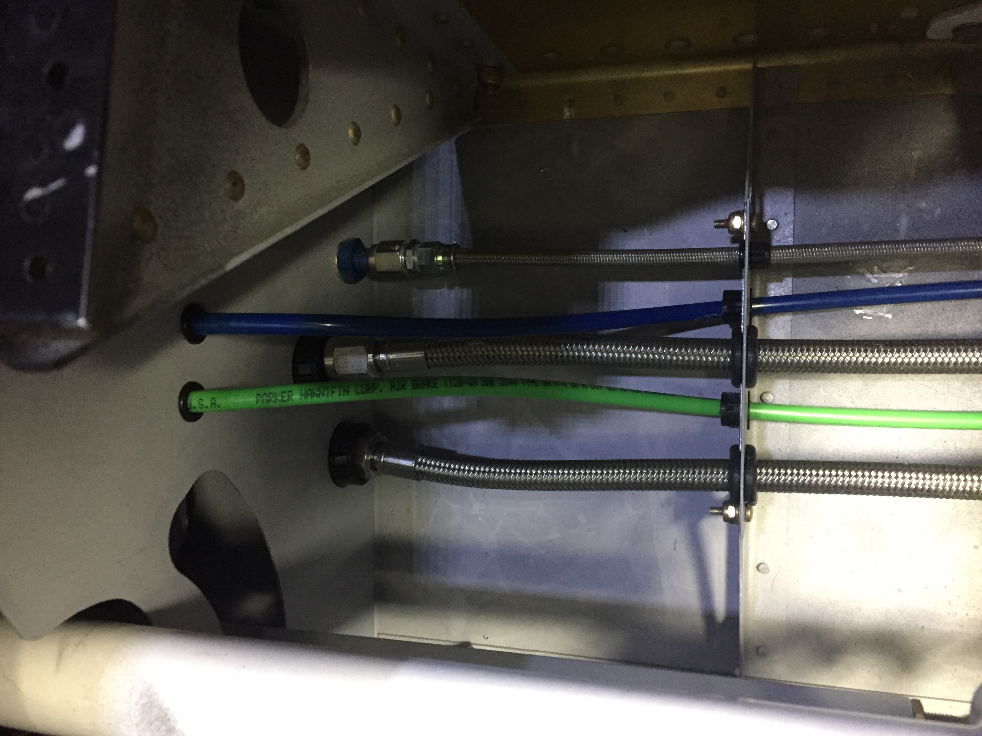
The pitot / AoA tubing needs to run across the fuselage from the left wing to the right sidewall, so I put two holes in the tunnel and used free holes from the fuel line anchors to run the blue and green tubing.  The wing is already plumbed, so these lines will connect with those from the wing with two connectors and be done.

Finally, I put the 30 amp Schottky diode on the firewall between the shunt and engine fuse block.  I had this in my electrical design but just in the wrong location.  It provides redundant power input to the engine fuse block only, keeping it from backfeeding the rest of the electrical system.  The power comes in from the emergency engine power switch which comes from the battery to the fuse block.  Big picture, it is a redundancy for the single point of failure of the master contactor or short in the system.  A complete electrical failure or engine stopping SOP will be to turn off the master switch (leaving PFD, MFD, and G5 operating on independent back up batteries) and switch on the emergency engine power switch.  If the battery has any juice at all, it will go only to the engine fuse block.

Light at the end of the tunnel

I have rearranged just a few items on the firewall and after getting confidence in drilling several holes, nothing was stopping me from drilling the remaining locations.  The toughest was the large hole for my insulated pass through for the main power wire.  I made the mistake of using a unibit and it really made a mess of the job.  In the end, it turned out okay, but I used that as a lesson to chain drill all future large holes in stainless with a #40 bit.  I needed to get the nutplates installed and all components temp mounted to ensure a proper layout so I could move on with the firewall insulation.

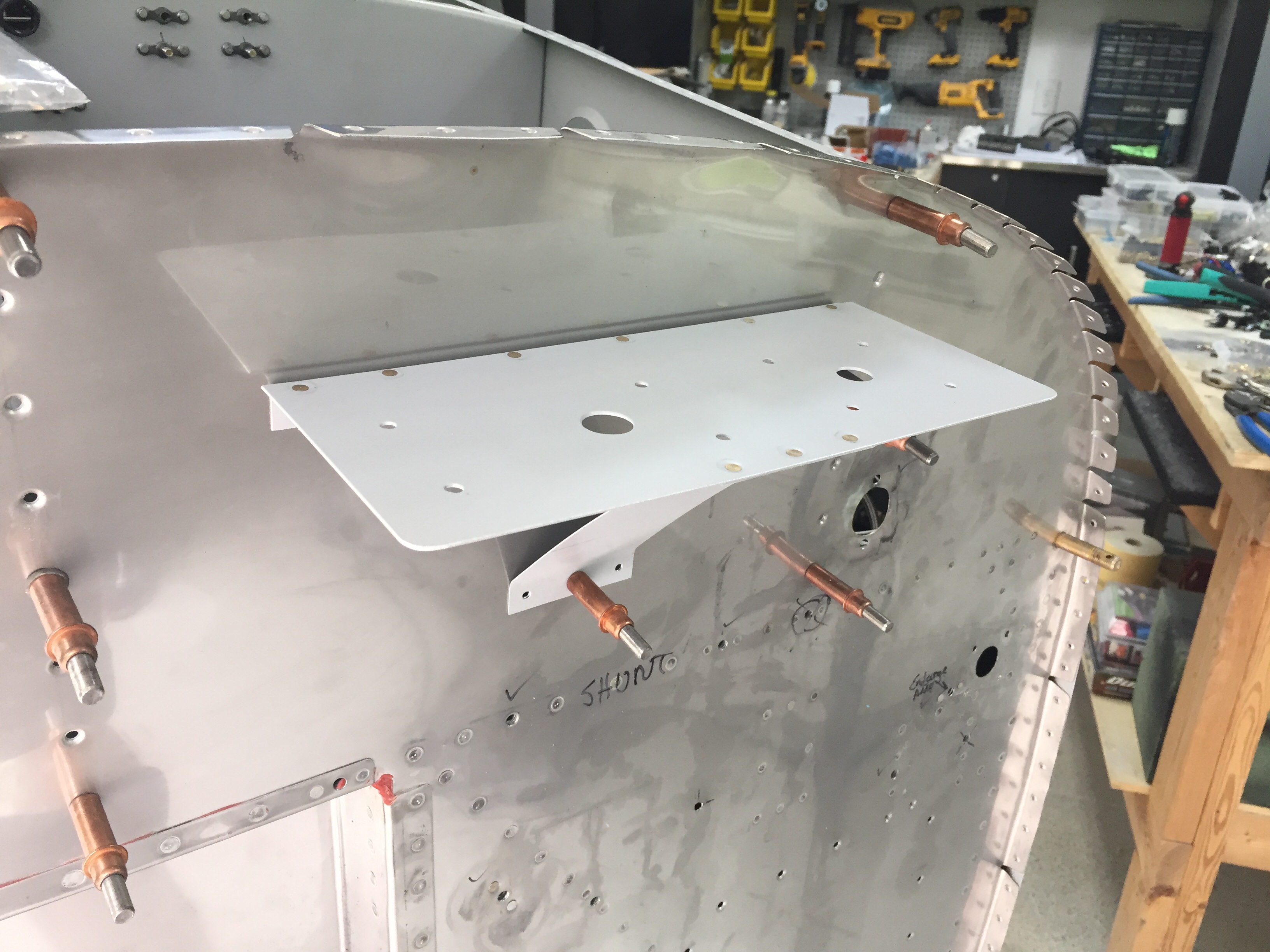
My two GPS antennas will be firewall forward just below the cowling as others have done, so I built a shelf for the AFS and IFD antennae.  The cables and wires will go through a dedicated pass through just below the shelf.   I ordered and will be using high-temp silicone grommets from ACS for these and the control cables going through the firewall.  They will be sealed with Firestop per the plans.

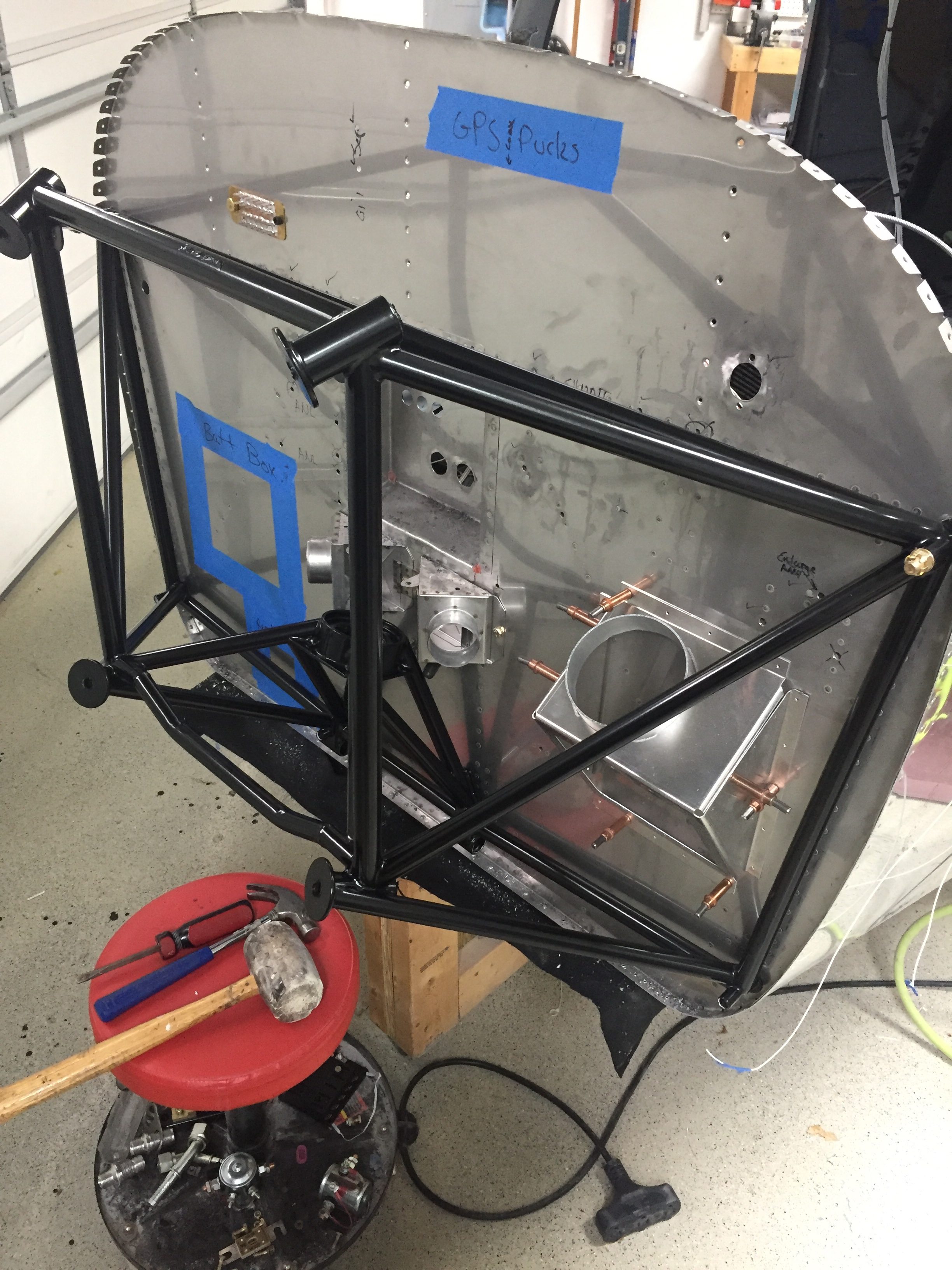
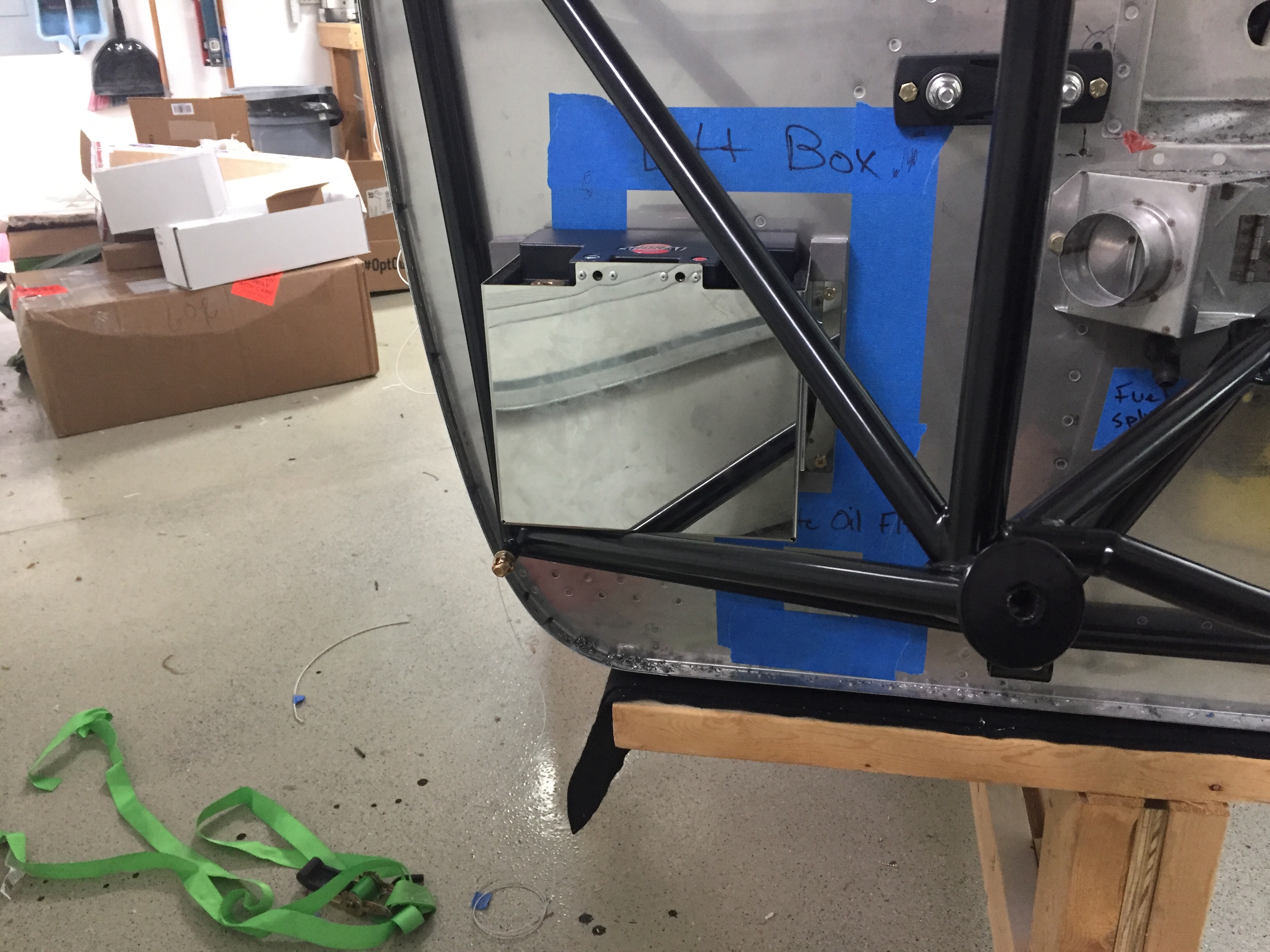
I decided to have the engine mount powder coated black just for a little extra pop and get rid of the white.  It came out nicely and I went ahead and drilled the holes to get it ready to mount.  I didn’t have to do too much finessing to get the holes lined up and it proved to be a quick job.  That also allowed me to position the battery box and ensure clearance for the battery to come out without having to remove the box from the firewall, again thinking about maintenance down the road.  The box is insulated and made by EarthX but is about a 1/4″ too shallow for the Shorai battery.  I used some spacers and high temp foam to stand it off from the firewall and allow just enough room for a snug fit.  The retainer of the box has a bracket to mount a 1″ blast tube which will come from the rear baffles for battery cooling.

The Shorai battery was a last minute decision over the EarthX for a few reasons.  I spoke to a few other 10 flyers who have had EarthX failures and while the service to get them replaced was excellent, no root cause could be found.  Further more, the batteries have the internal BMS which will protect the battery’s voltage from dropping too low.  There are a bunch of pros and cons that I won’t get into about BMS but I decided I’d rather kill a battery than killing myself because my electrically dependent engine quite to preserve a $300 battery.  The Shorai also has a higher aH rating, at 36 meaning in theory I’ll get more power for longer than the EarthX.  It does not have an internal BMS so will die giving it’s last bit of power to me, which is what I want if both of my alternators fail and I need to keep flying.  It’s about the same size, the same weight, and cheaper to boot!

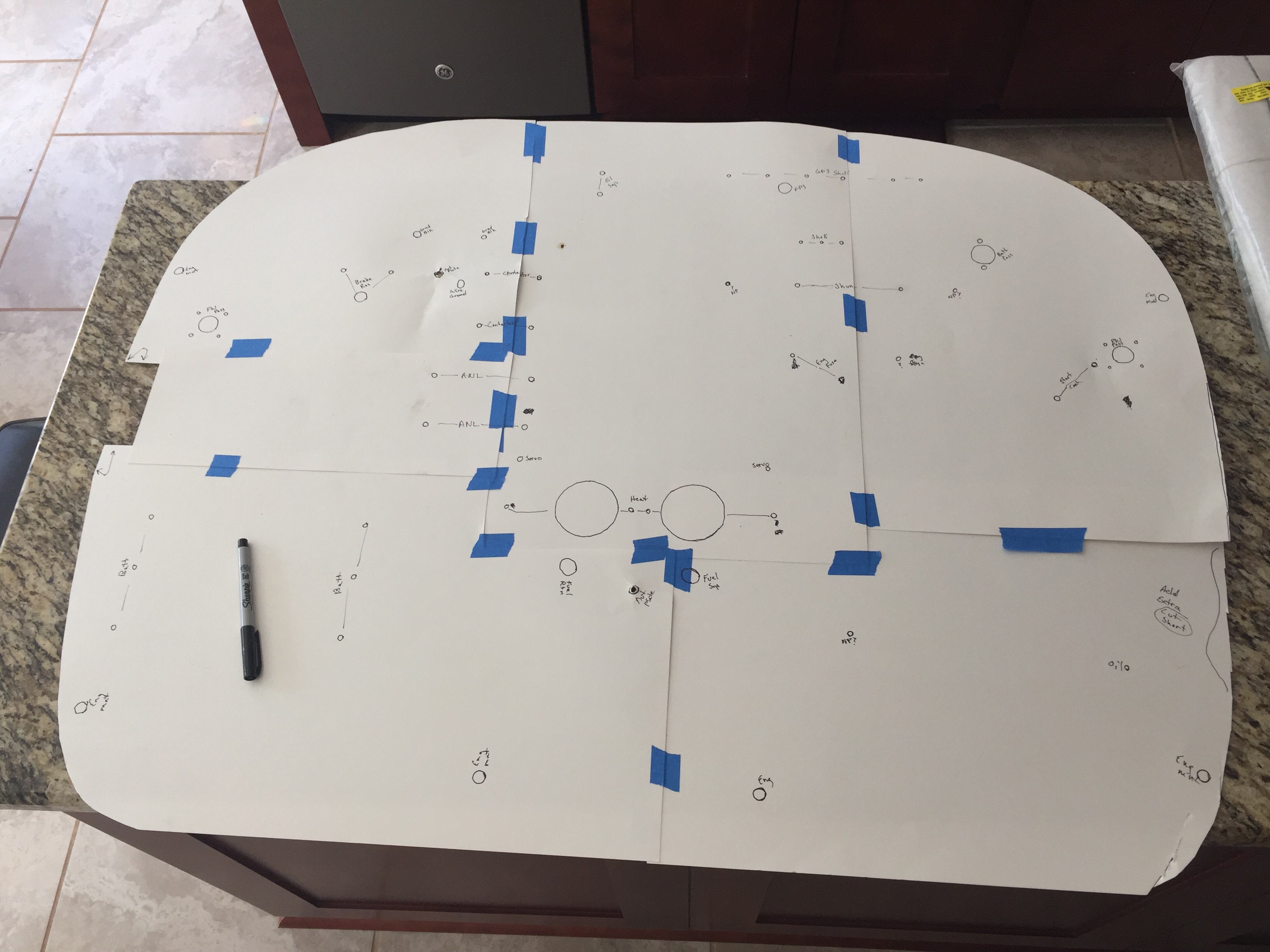
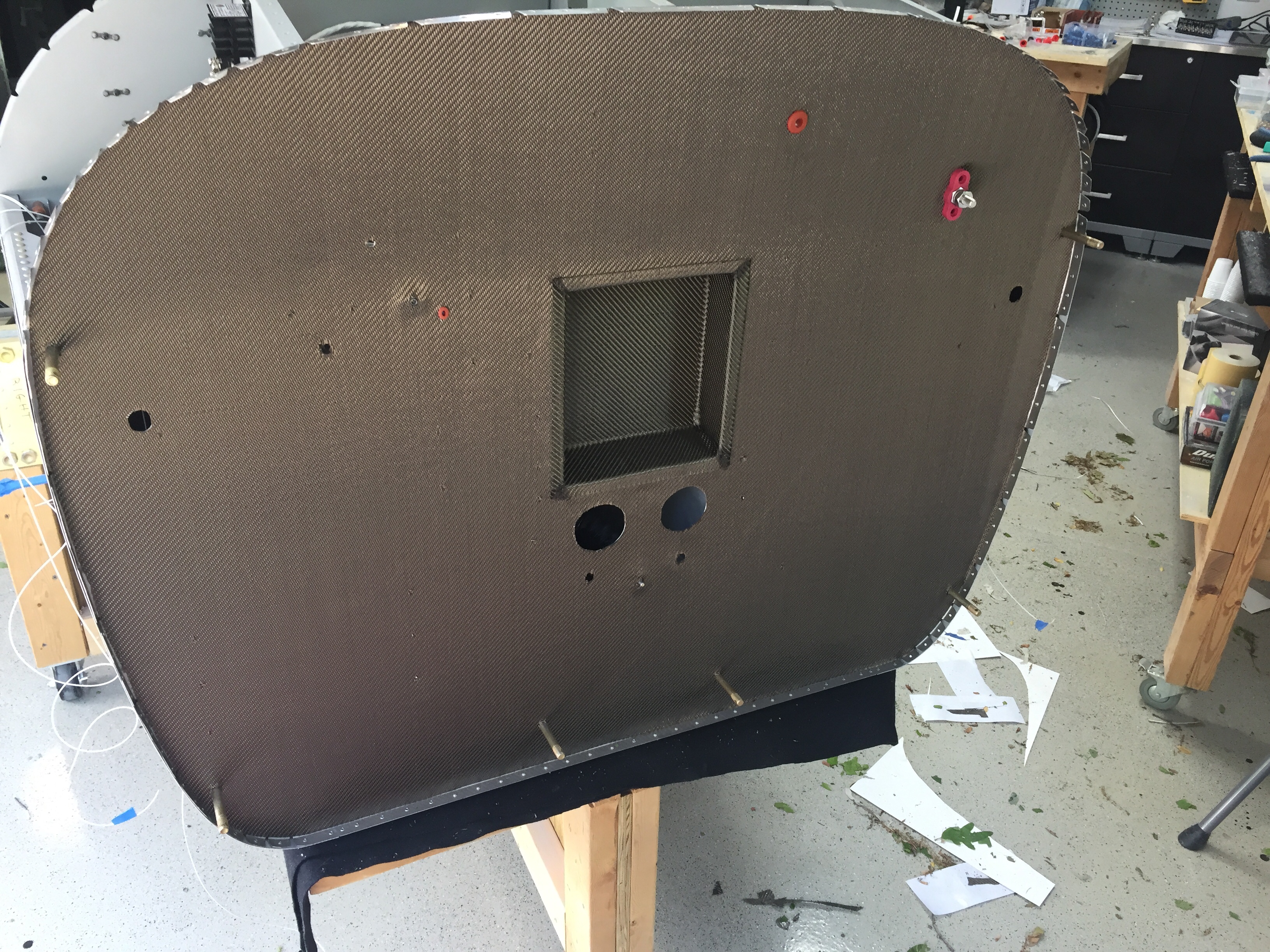
Once everything was drilled and nutplates installed where needed, I made a template of the firewall and holes on poster board to transfer over to the lava shield insulation mat.  I got the product referral from John Walker and have seen his up close really looking and performing well.  Plus, it’s a lot easier to install and work with than the fiberfrax sandwich, in my opinion.  The lava shield is a carbon fiber material with a self adhesive backing.  I trimmed most cutouts with a razor and decided to just match drill the small rivet and bolt holes once it was on the firewall.  It was pretty easy to apply the mat to the firewall, taking my time and treating it like a big sticker.

I cut out the area covering the recess and used scrap material to fill in the edges of the recess.  I chose to glue the edges, as the material is a bit stiff and didn’t like the sharp outside radii.  I’m really happy with the finished result, not only aesthetically, but functionally.  It should provide a nice barrier for heat transferring to the cabin and gives the firewall a nice finished uniform look.

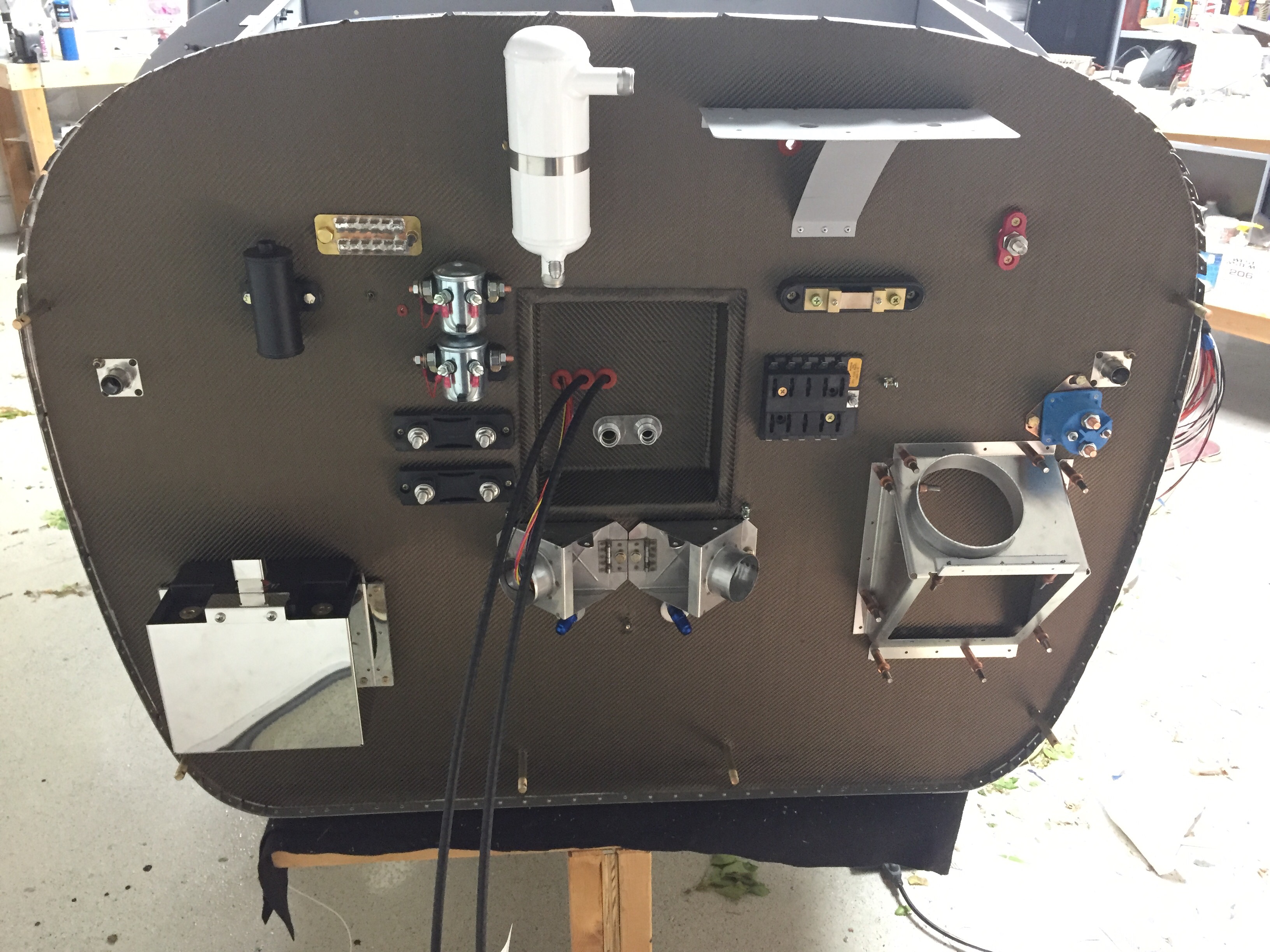
It was finally time to bolt all the stuff to the firewall and get my workbench cleaned off.  Again, having the forward fuselage section removable at this point really made the job easy as I could just reach around and secure nuts, etc. on the cabin side of the firewall.  I used nutplates on everything that would have a good chance of needing removal but used nuts on the few items that would only come off once or twice in the plane’s lifetime or could be serviced while installed.  It’s pretty cool to step back and look at all the components up there and seeing how it’s all going to fit together.

I am pretty confident the locations will allow clearance with the engine except the oil separator.  I’m afraid it’s going to hit my stand by alternator, but only time will tell as the measurements I’m getting from others is a bit misleading.  We’ll see and if need be, it’s a easy fix.  I have the main power pass through on the upper right, a 3/4″ pass through on the left and right side, grounding tab and main grounding bolt on the upper left, and GPS shelf on the upper right.  The two contactors on the left side are GPU (on top) and batt master on the bottom.  Two ANL fuse blocks are below those, one for each alternator.  The prop and throttle cable (no mixture with SDS) come from the center and I’m using the third hole for the heat vent servo wires.  On the right, the AFS shunt will measure alternator current going into the system and the starter contactor is at the stock location.  The fuse block is for all of the engine components related to SDS including coils, ECUs, fuel pumps, etc.  Finally, the oil cooler has been modified to fit the larger 2007X oil cooler and will have a damper controlled by a TCW servo just like the heat vents.

Lot’s of progress that is really rewarding as I’m slowly emptying all the boxes and cabinet shelves holding purchase but uninstalled items!  Next up will be attacking the throttle and center console along with the rest of the instrument panel and putting the forward fuse section on for good.

Wired for moving day

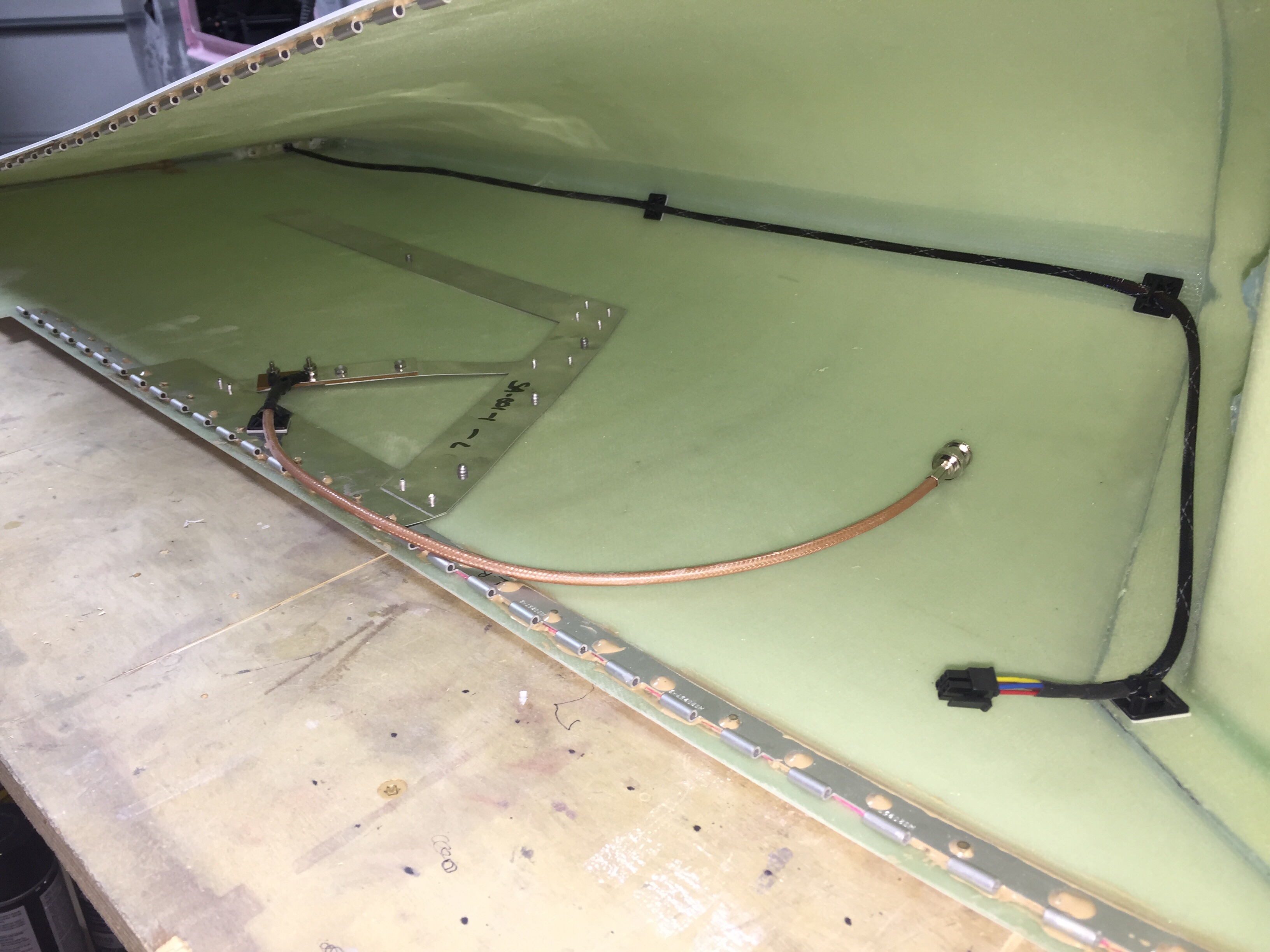
With the tips fitted to the wings, it’s time to run some wiring and finish up the wings. I integrated the Archer nav antenna into the tip mounting hinge which thus links the antenna to the wing for a proper ground plane, per the plans. I used a few pop rivets through the bottom of the tip to secure the antenna in place. I wanted to make the tips easy to remove, so I used bulkhead BNC fittings for the coax on both end of the wings.

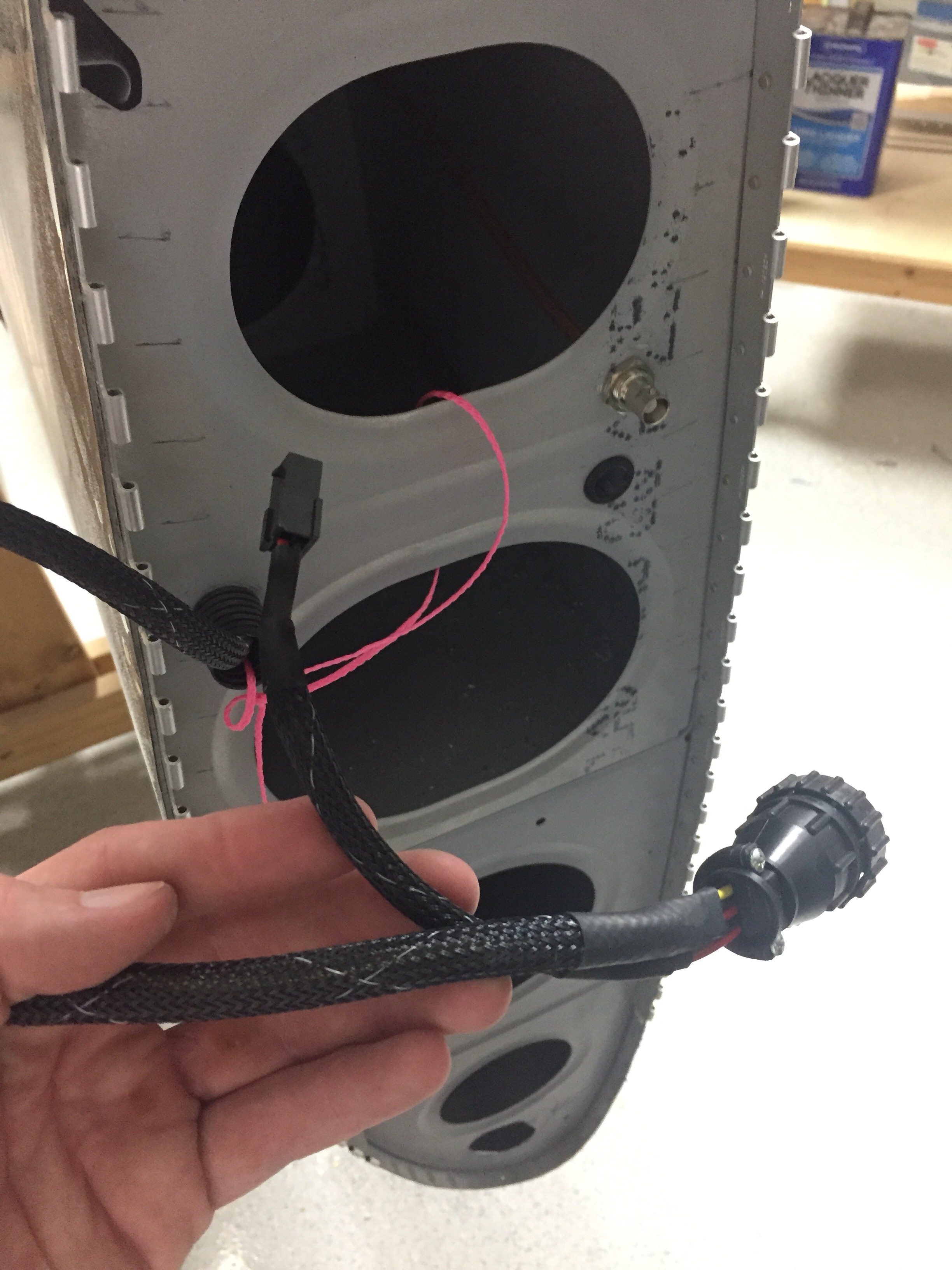
I also ran the wires from the trailing edge position / strobe light up towards the main lighting modules and installed a micro fit connector so that the lighting module can be removed for future maintenance / replacement should the need arise. Again, all of the wiring has been documented in Visio including pin outs on each connector so I’ll be able to reference it long after I’ve forgotten how or why I did it this way!

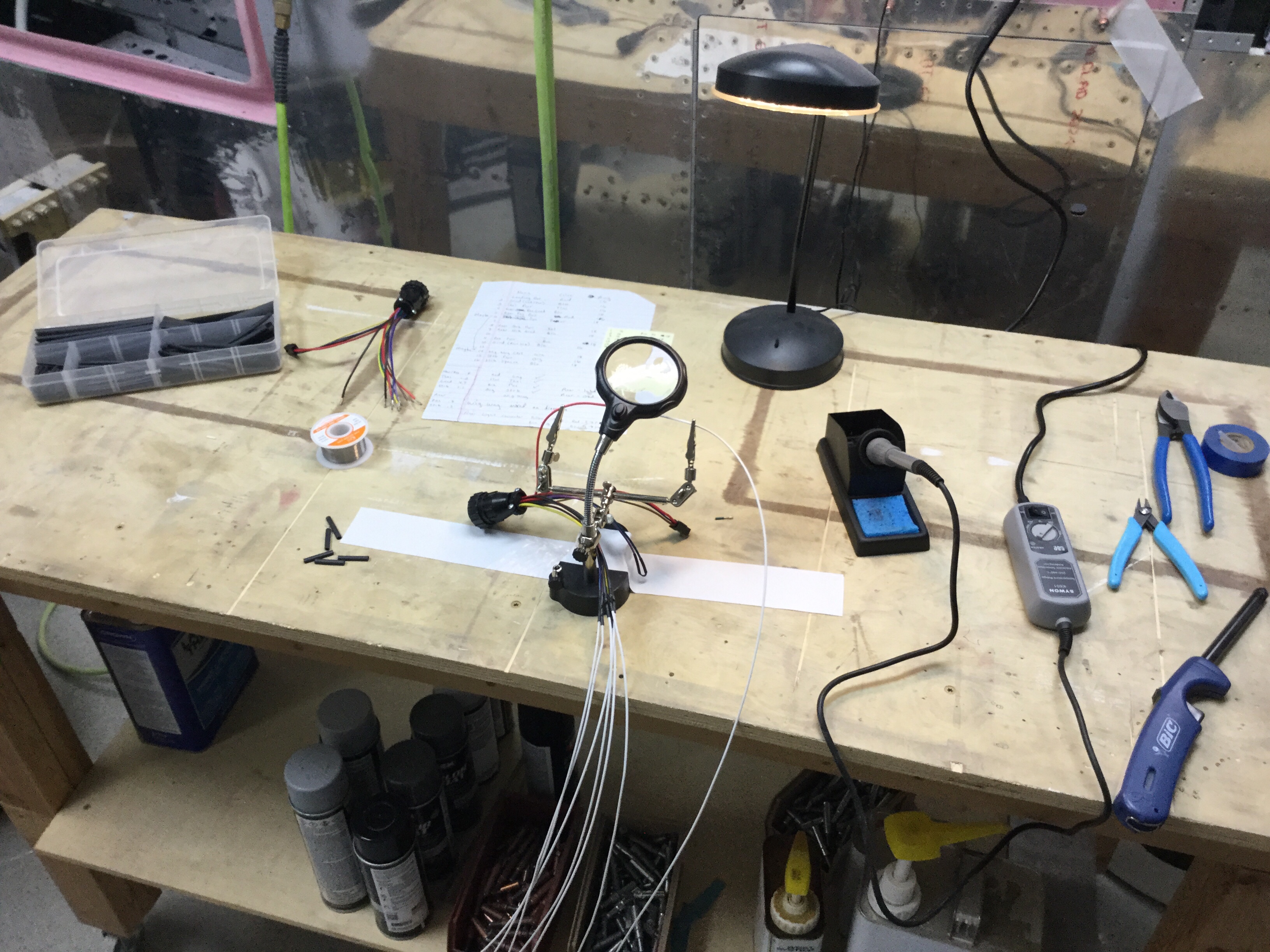
I used CPCs for the main wiring runs and am very pleased with the setup. Some folks avoid connectors like the plague, but I don’t see them as failure points if they are done right and properly tested / treated. I checked continuity of each wire after running them all so I know everything is ready for plug and play. The wing root connectors include those for the pitot heat and AP servo on their respective wings. The aileron trim servo is on it’s own micro fit connector due to the small wire size. I’ve gotten really proficient at the micro Molex connectors and really like them.

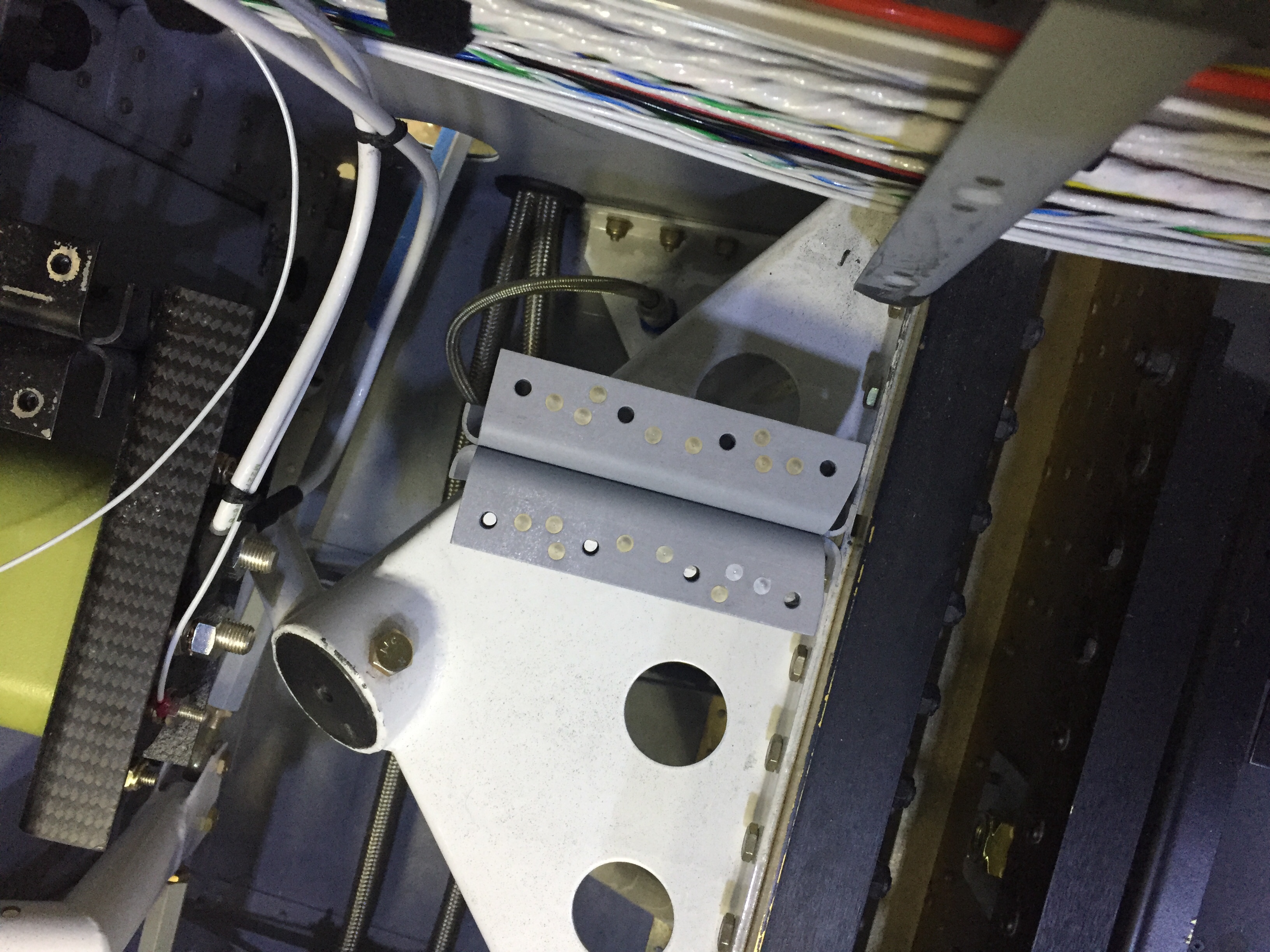
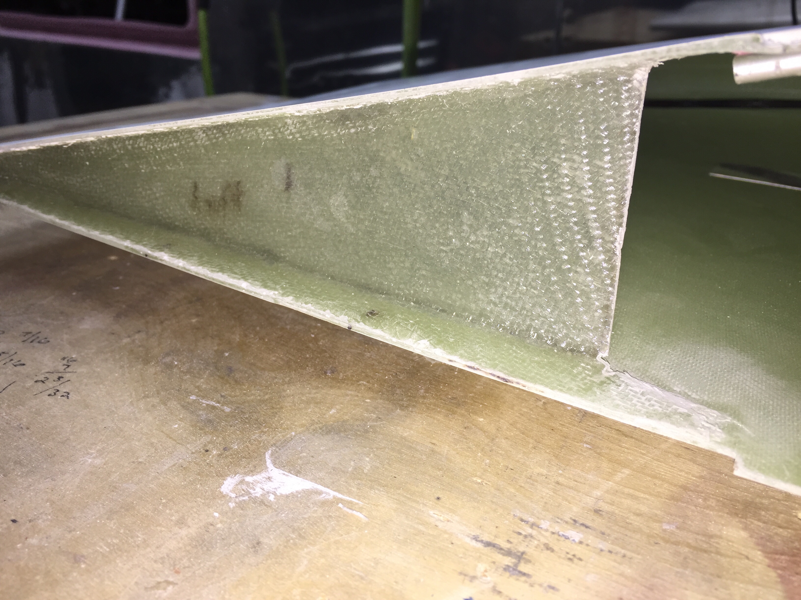
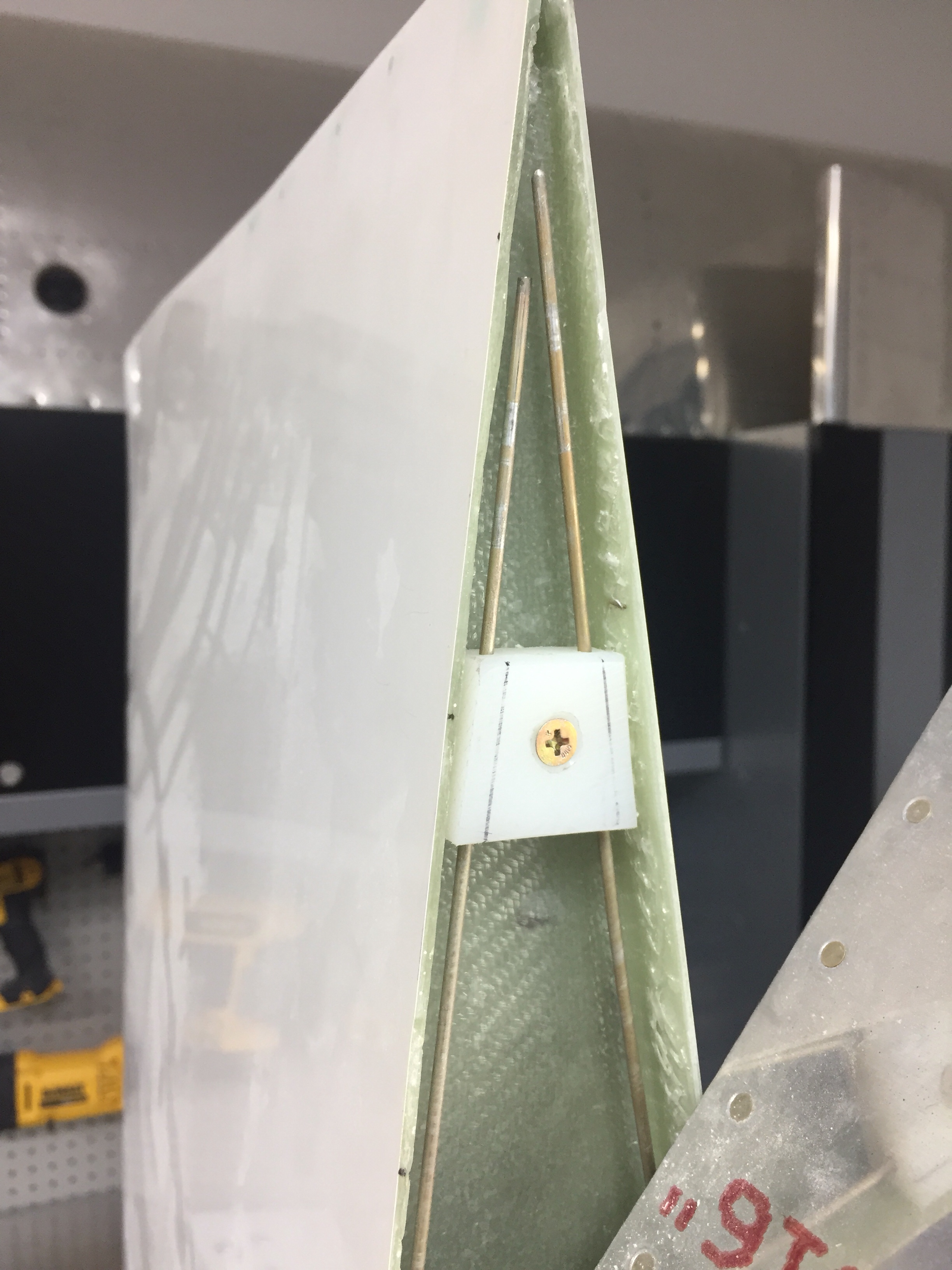
I also had to layup a small rib on the trailing edge to not only support the shape of the tip, but also provide a mounting surface for the hinge pin retainer. I used a trimmed block of delrin and nutplate to secure the pins. This keeps the pins inside the tip profile and thus unable to work themselves loose. They also butt up against a stop on the leading edge. I didn’t want to put a bend in them, as it’s very easy to use a drill and spin them in / out.

The only system component not installed in the wing is the OAT sensor which I’ll get with the avionics in a few months. That’ll be simple to put into an access plate and a string is still waiting to pull wires through the wing root.

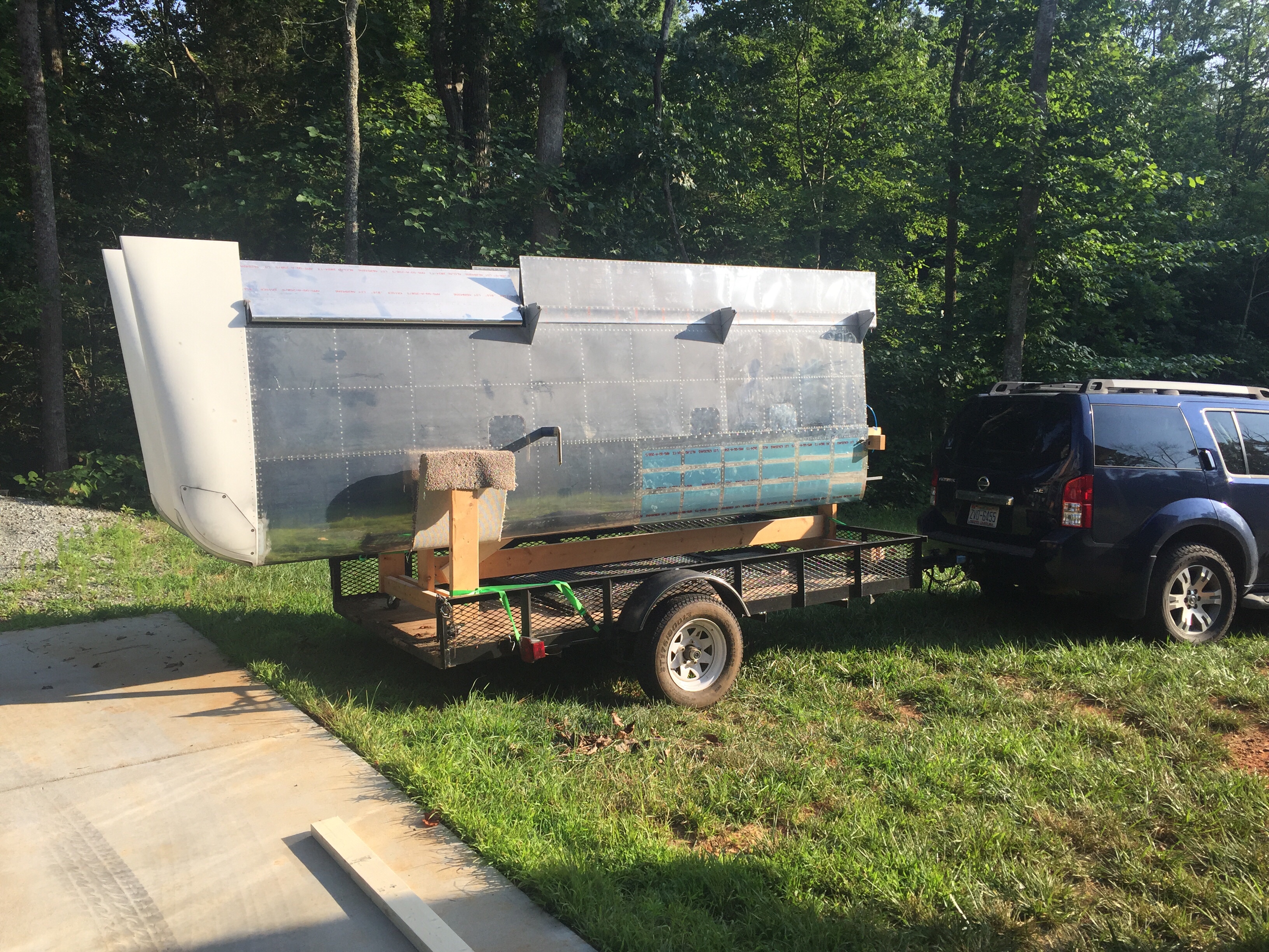
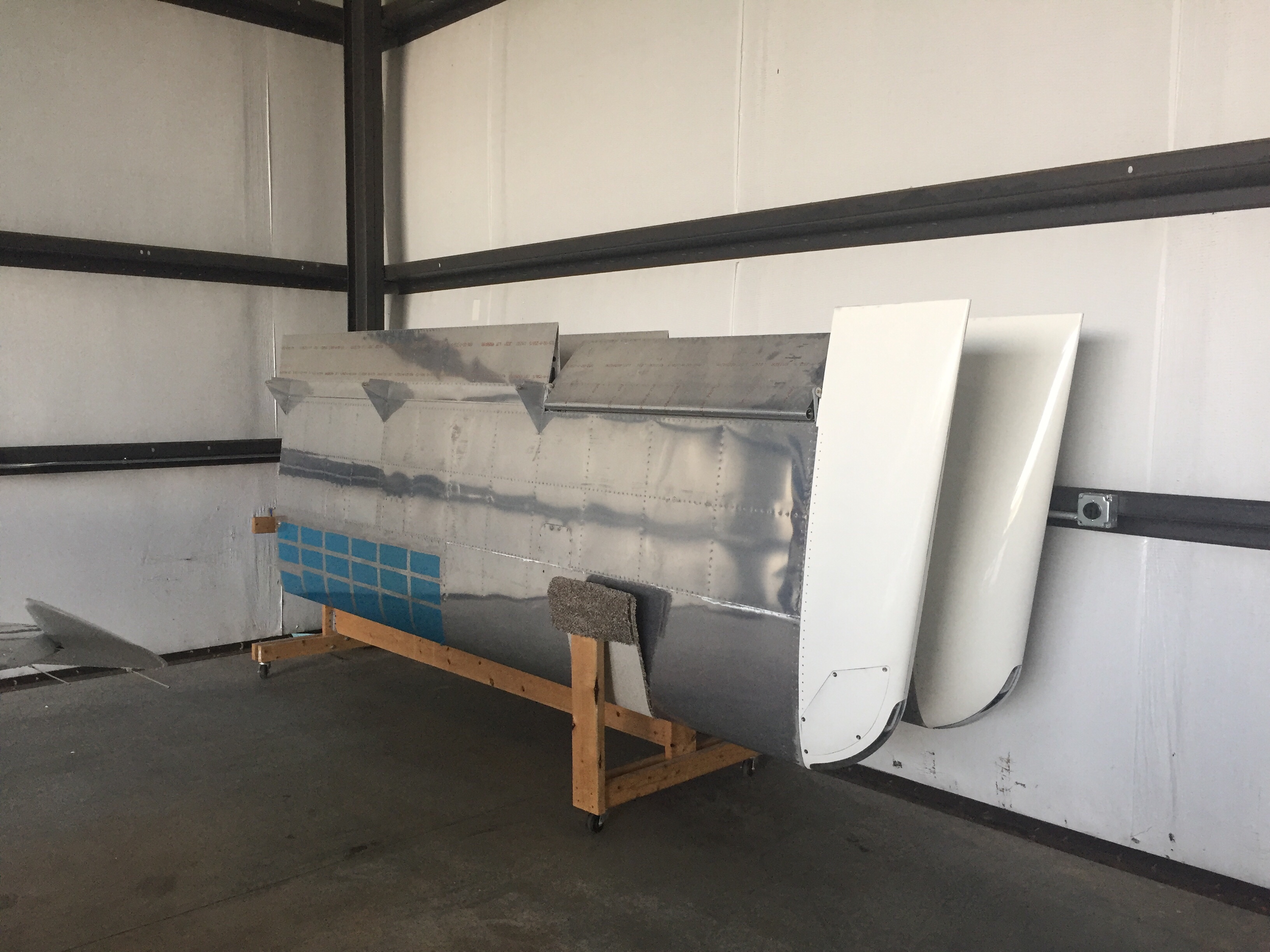
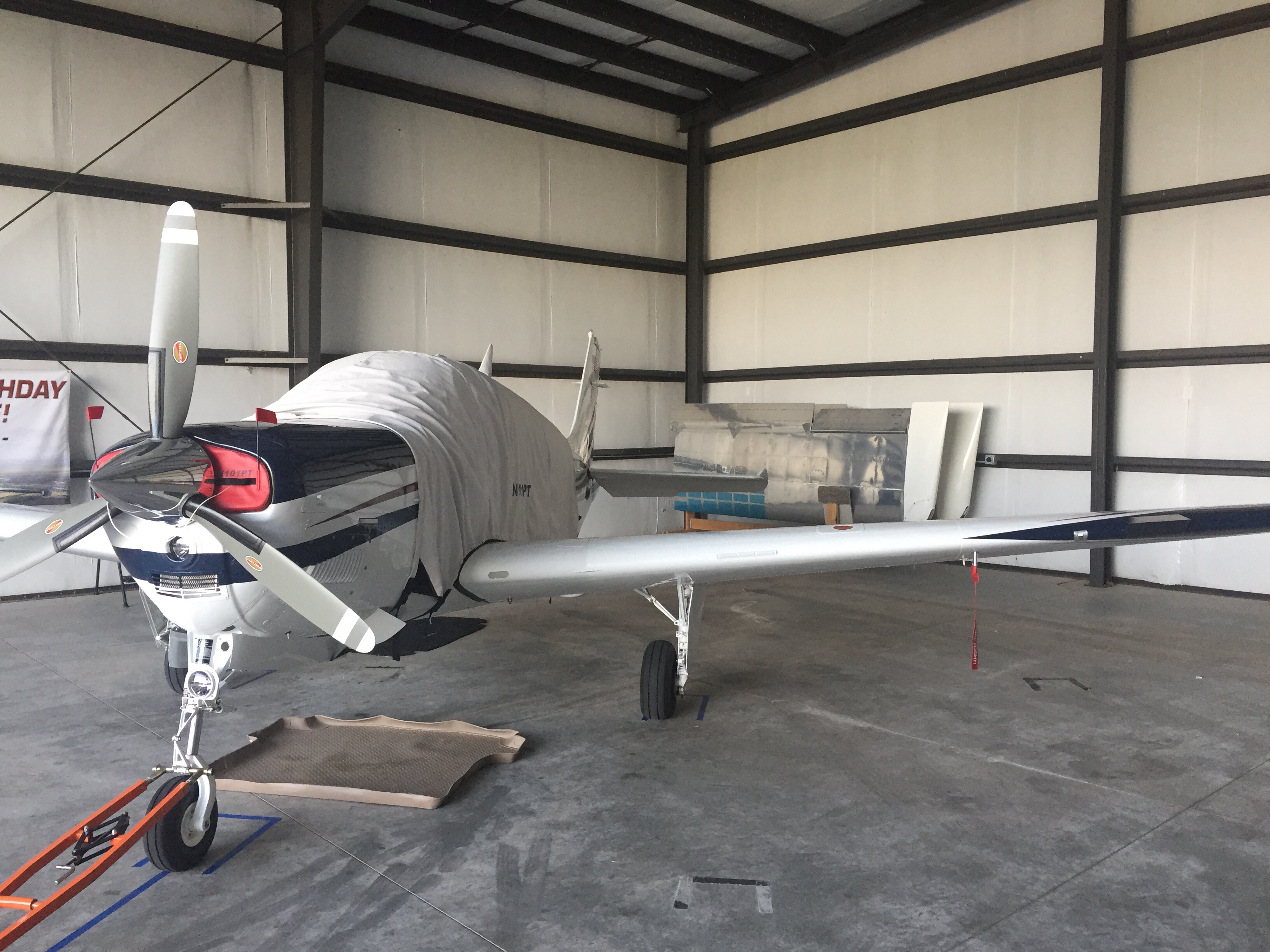
Since the wings are all complete, I need to get them out of the garage to make way for the finish kit and make me feel like I have real airplane parts in a hangar. My Diamond bros graciously offered a corner of their hangar for me to store the wings in until our hangar is available. So moving day came and anticlimactically went! It was like I designed the wing rack for the trailer and with Ron’s help, they rolled right on and off. We used a few tie downs and took our time on the 10 minute drive to the airport with no damage reported. I hope the fuselage move goes this smoothly!

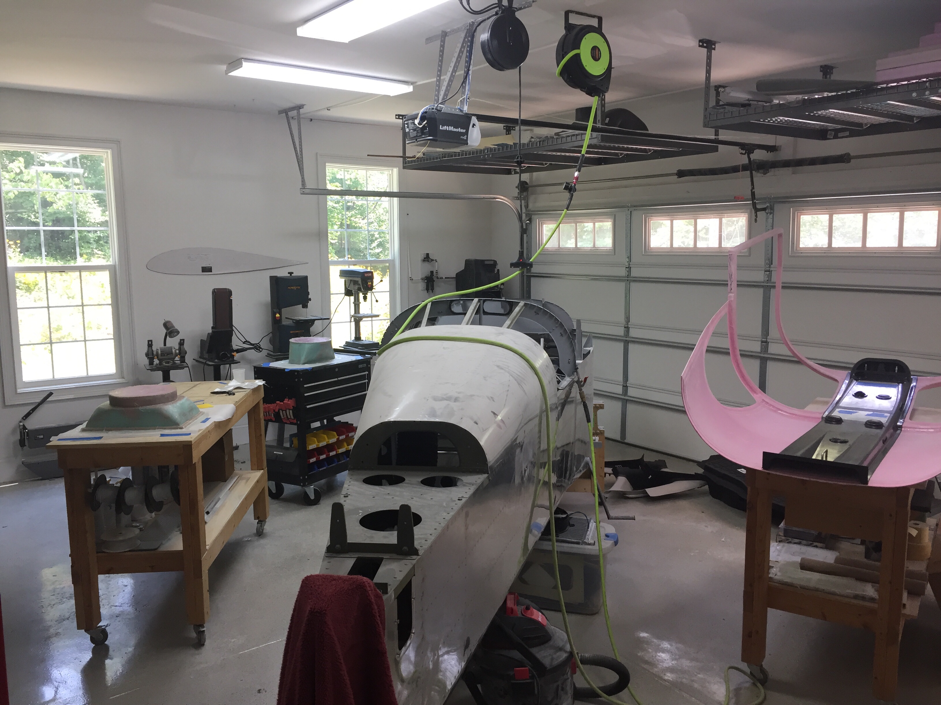
Bonnie the Bonanza is now babysitting RV wings. Meanwhile, back home the shop has so much room for activities such as finishing the cabin top and getting ready for the finish kit and cowling which are due to arrive early August.

Staying in the lines

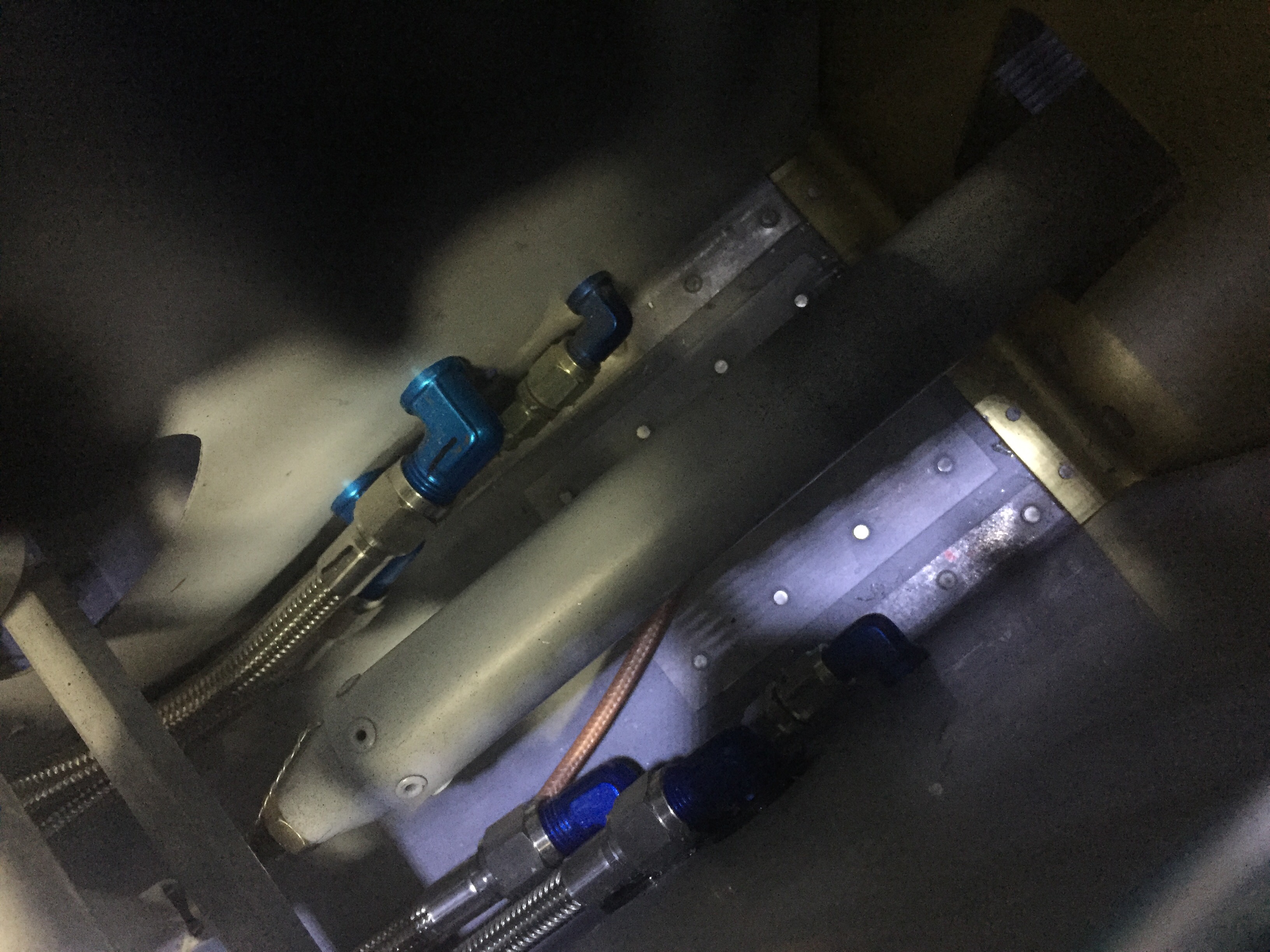
Throughout this progress, I’ve been finishing up the brake lines.  I ordered extra line for the run from the firewall to the gear legs and got them all fabricated.  The lines weren’t hard to make, but it was a bit tedious.  I am happy with the end result, however, and think that it will provide many years of great performance without having to worry about replacing tubes.  I do need to get some spiral line wrap to prevent chafing and that will allow the lines to be a bit better secured.  Mark Ciglia put his parking break valve in place of the firewall connections, which I’m mad I didn’t think about.  It makes it a bit cleaner and eliminates one extra set of lines, but oh well.  It’d cost more now to redo it.  Note to other builders!

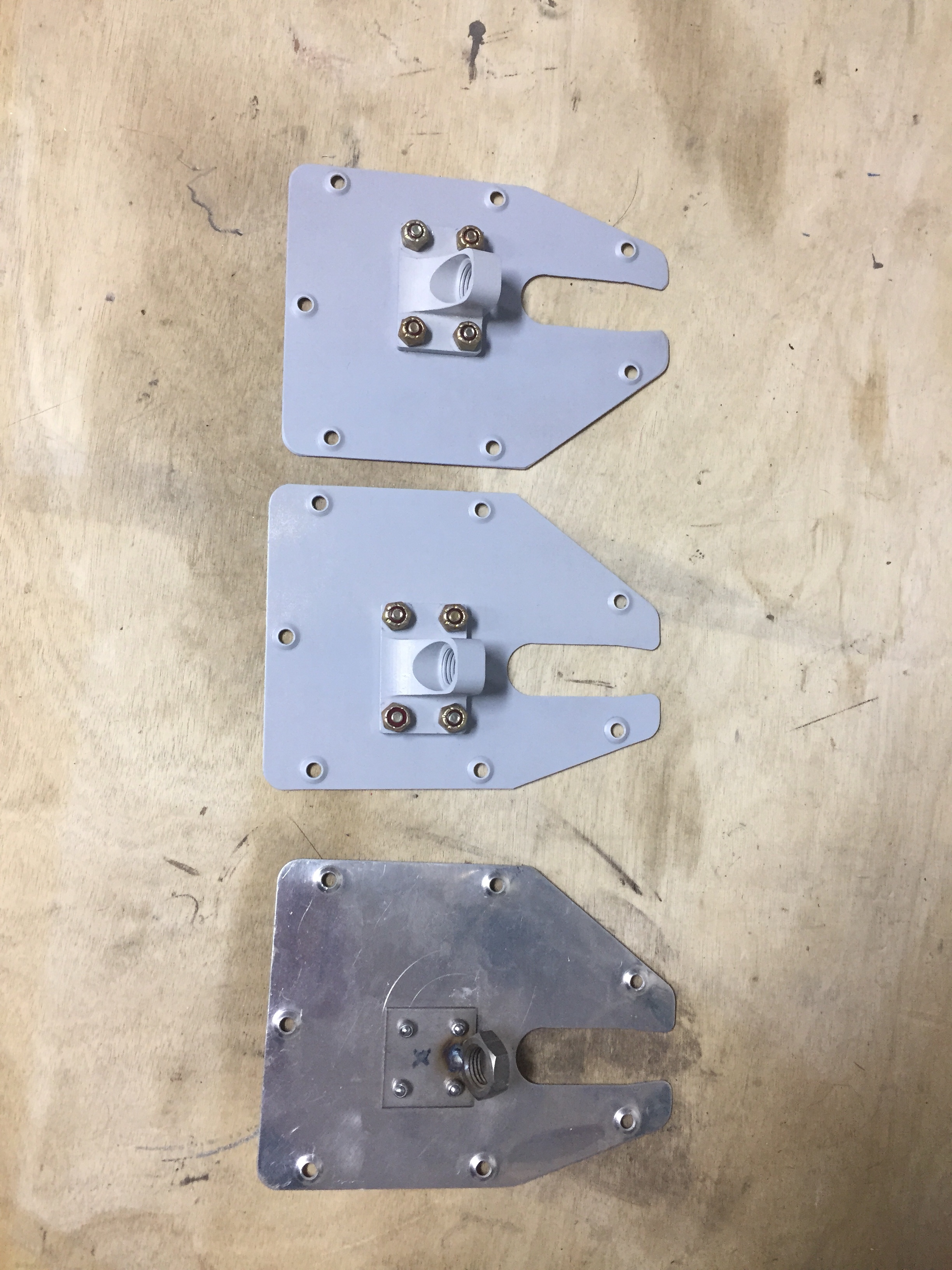
I also knocked out a few little projects, one being making new elevator trim bracket panels.  I had the beefed up fittings sitting in the parts bin and finally ordered the new access panels.  After countersinking and priming, the parts are ready to roll and comply with a SB from Van’s from many years ago.  This is a common upgrade and an easy one at that.
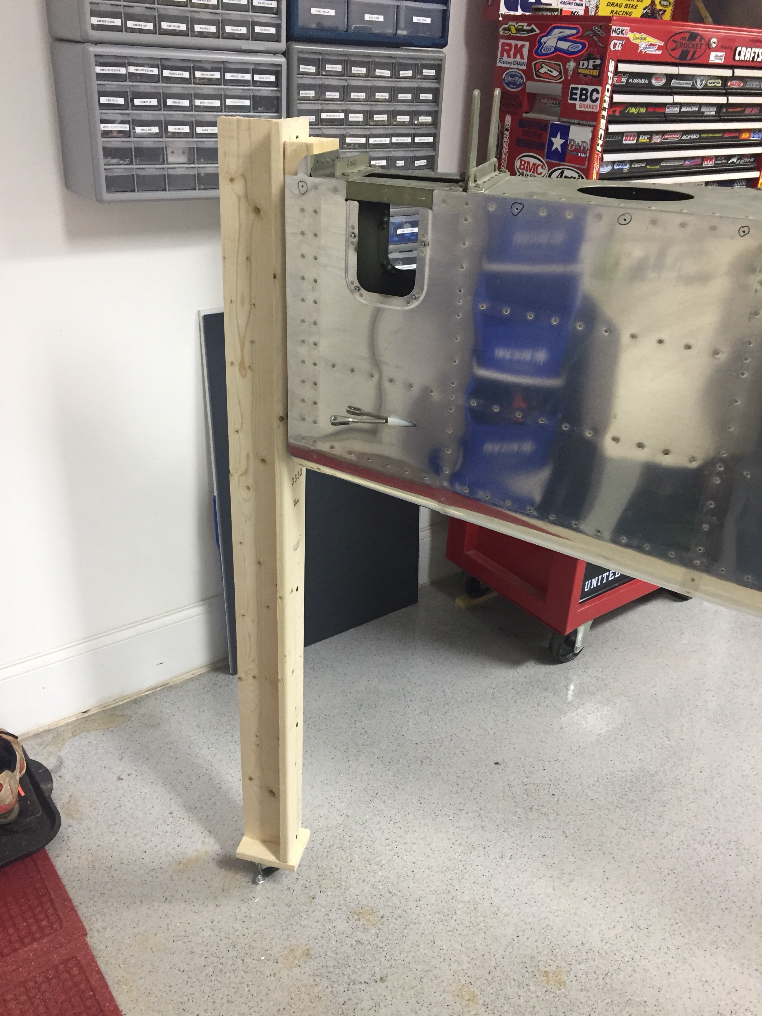
Another little project wasn’t so little.  I saved up a few tasks that needed to be completed inside the tail cone for one evening so I would only be crawling back there once (this time).  The first was to support the tail better.  I used two 1×4’s to bolt to the horizontal stabilizer mounts and put a caster on the bottom.  While the fuselage cradle has been great, the rear support isn’t far enough back to support my weight so far aft without something heavy like an engine hanging off the front.  So this was an easy fix and doesn’t take any room up in the shop.  It’s still very easy to roll around and reposition as needed.
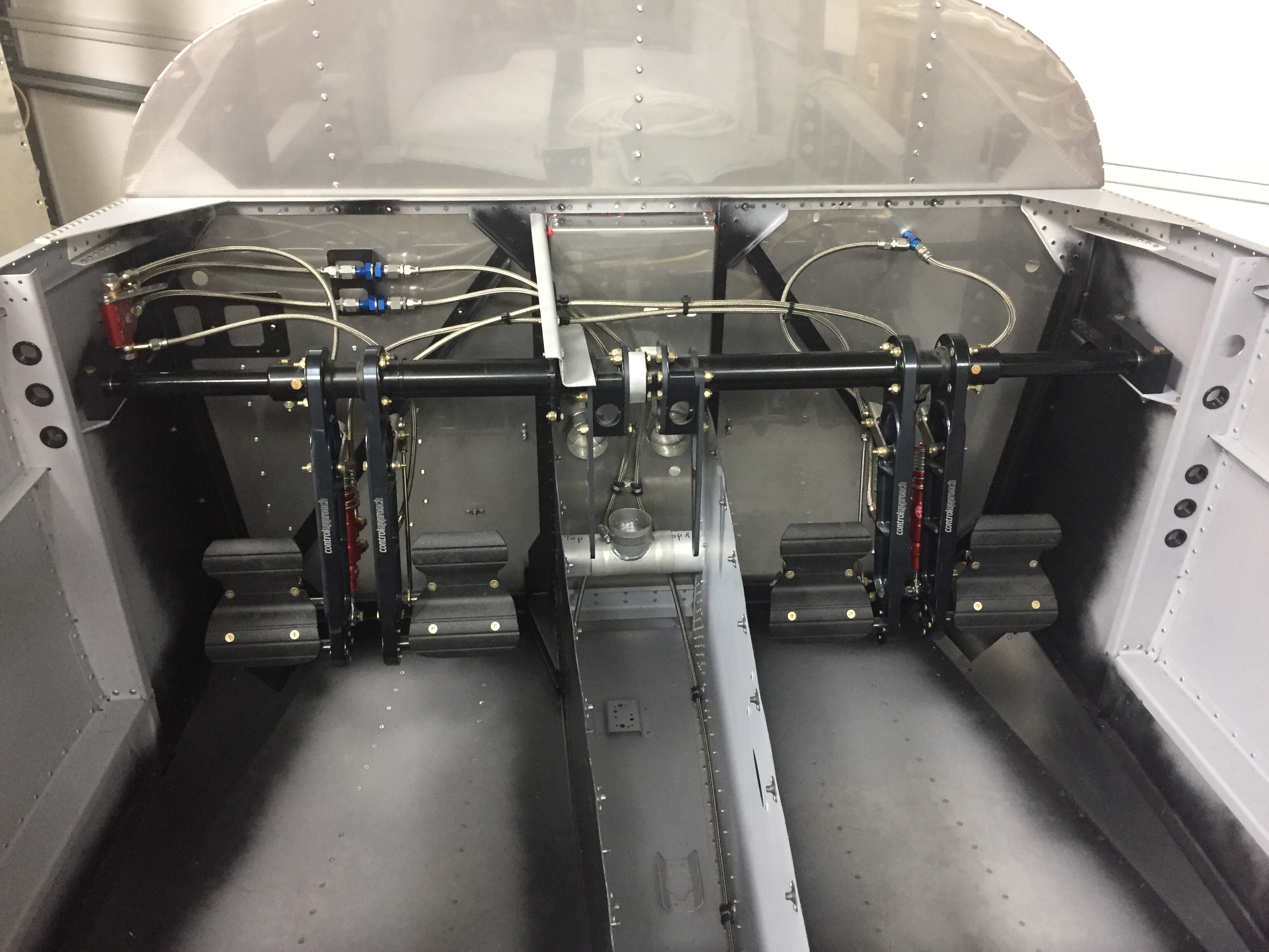
Inside the tail cone, I mounted the new static ports with pro-seal (no rivets this time) and hooked up static line that runs to where the ADAHRS will be mounted just behind the baggage bulkhead.  The new static ports look way better than the original ones and I’m happy I made the change.  The Safe Air 1 line kit makes it easy to run the tubing and create a leak free system.  I also ran the rudder cables through the bulkheads and snap bushings.  Ironically, the heads of the cables wouldn’t fit through the bushings without removing them and squeezing a bit.  So basically, the cables were a pain to run instead of a quick two minute job.  Lots of those in the build, I guess.   I got them hooked to the arms on the rudder pedals which are inside the tunnel with the Control Approach pedals.   With the A/C in there, it’s a tight fit for me!
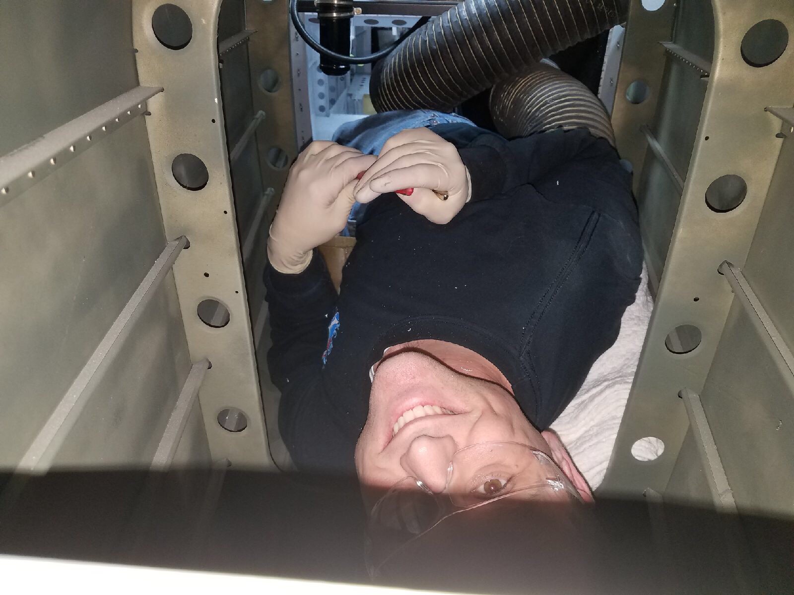
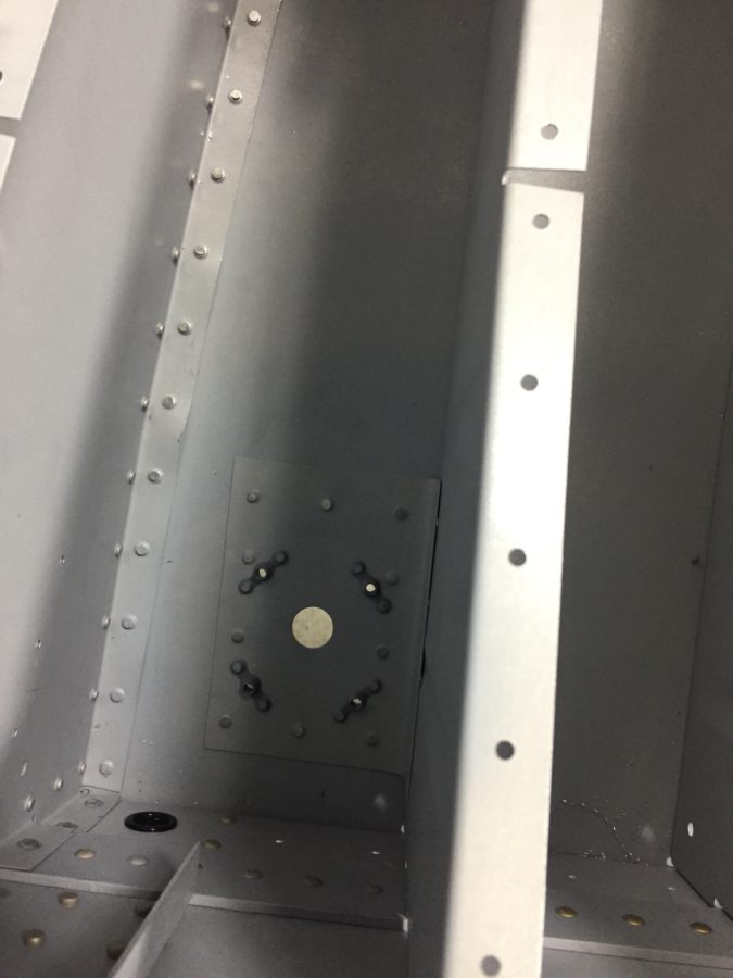
Lastly, I installed the doublers along the center of the fuselage for the transponder and ADS-B antennas to mount to.  These will be Delta Pop blades and mount with two studs, so I need access from the tunnel / fuselage.  Easy enough with a second set of hands to man the gun and me bucking.
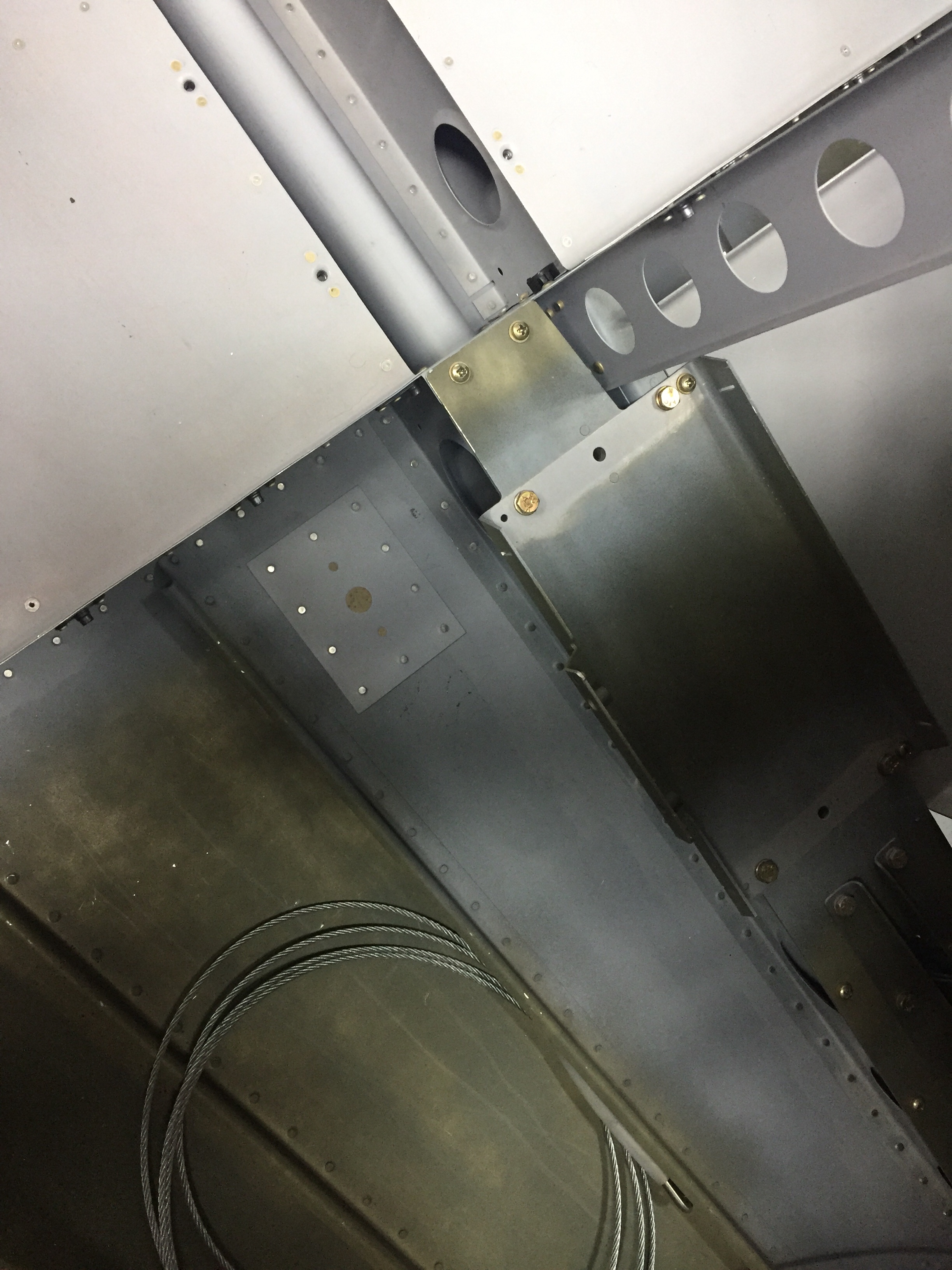
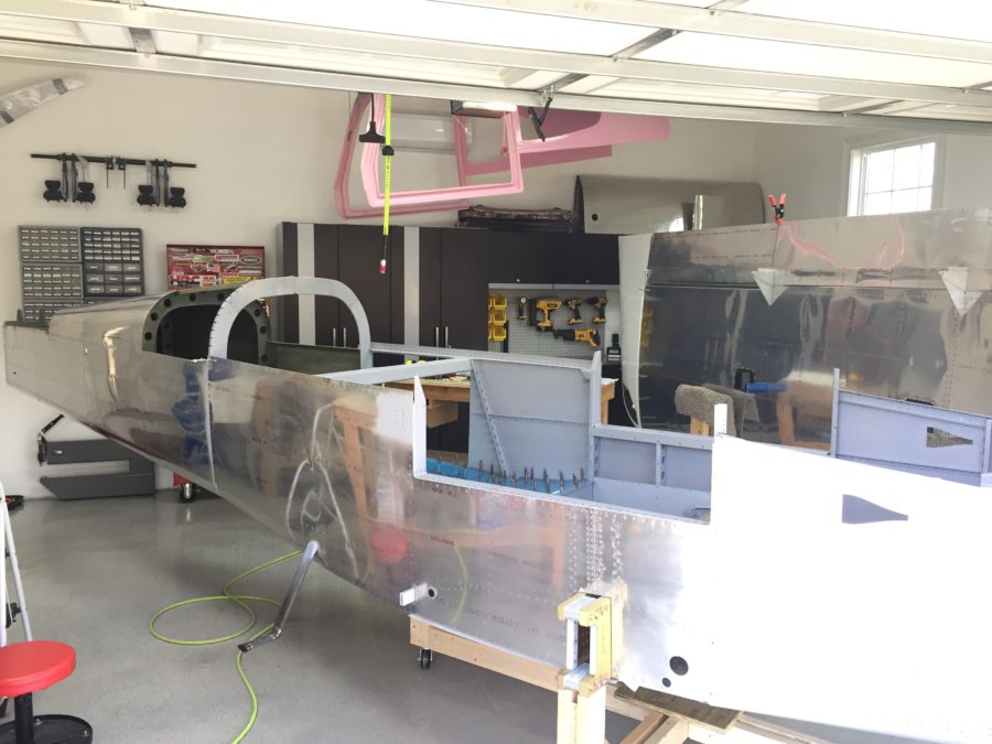
We have some catching up to do

Time has gotten away from this blog, so I have quite a bit of catching up to do. I also must admit that there were more than a few months that snuck by with no progress made on the project due to work, life, and other priorities. I’m happy to report that I’m back on the project nightly and am really making some exciting progress.

I left off with the tail cone repair and prepping to join the two sub structures. It was very anti-climactic to be honest! One rib worth of rivets required a bit of help from a friend to hit some rivets and boom, it was on for good. It really is starting to look like an airplane, or at least a canoe at this point. I’m very happy about the cradle on wheels, as the shop is getting a bit cramped on space, although I’m confident it will still be a nice workspace for the remainder of the project.

I pressed on with the steps, as you can see above and used the TCW step bushings to prevent the mounting bolts from crushing the tube and creating issues down the road. I attached the antenna doubters and am happy with the results. They are actually under the rear seat pans, not the baggage floor as previously mentioned.

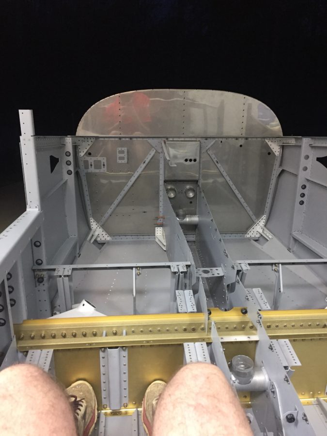
Next up is the baggage floor, rear seat pans, and rear bulkhead. Lots of drilling, deburring, and priming but the work went fairly quickly. One thing that has always impressed me is the size of the cabin in the RV-10 and now that mine is coming together, I had to see how roomy it actually is. First time sitting in the plane! And no, I didn’t make any airplane noises quite yet since I was sitting in the back seat. Plenty of leg room.

Lot’s more to catch up on in the next post.

Pop goes the rivets

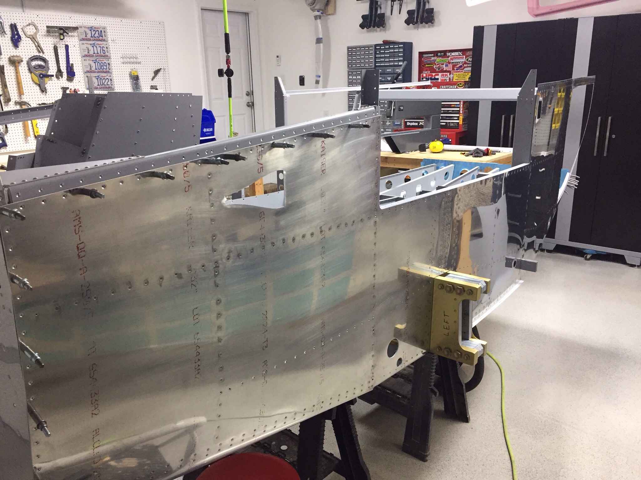
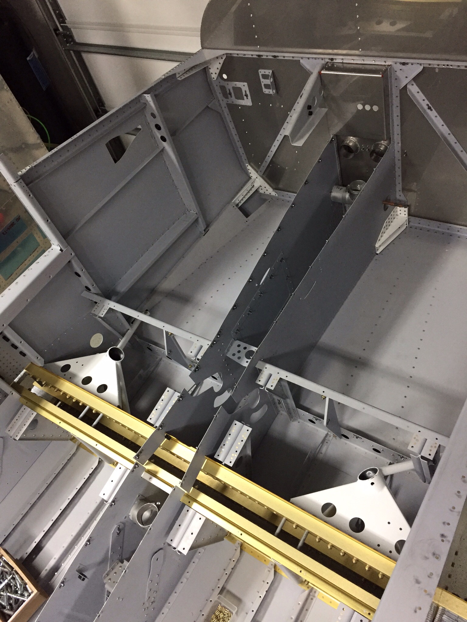
Section 29 has proven to be a lot of work but the results are more than worth it.  With the help of the Mrs. again, the four side skins are riveted on now and I’m pretty happy with the results of the bending.  I was able to get the new engine mount bracket drilled and riveted to the firewall with better results this time.  After the side skins were on, I was able to get the front floor panels on.  These are pop riveted onto the structure and I’m glad I’m not building the entire airplane with pop rivets.  They are almost more work than bucking.


The landing gear mounts had to be finessed into place and led to a bit of a panic attack on my part.  While bolting them in, I realized the spacers for the two long bolts weren’t fitting quite right.  After a lot of measuring, I determined the spars were a bit too far apart according to the plans.  If the spars are off, this could be a huge concern.  After a post on VAF and a call to Van’s, I figured out that I didn’t remove the vinyl from the spacers and also didn’t insert the right spacers into the spar during construction.  I lucked out though and the spars are only .002″ off after its all said and done. That was close enough for me and Van’s so I pressed on with as it was.  Adding a thin washer fixed the spacers and the other two for the right side was cut a 1/32″ longer.


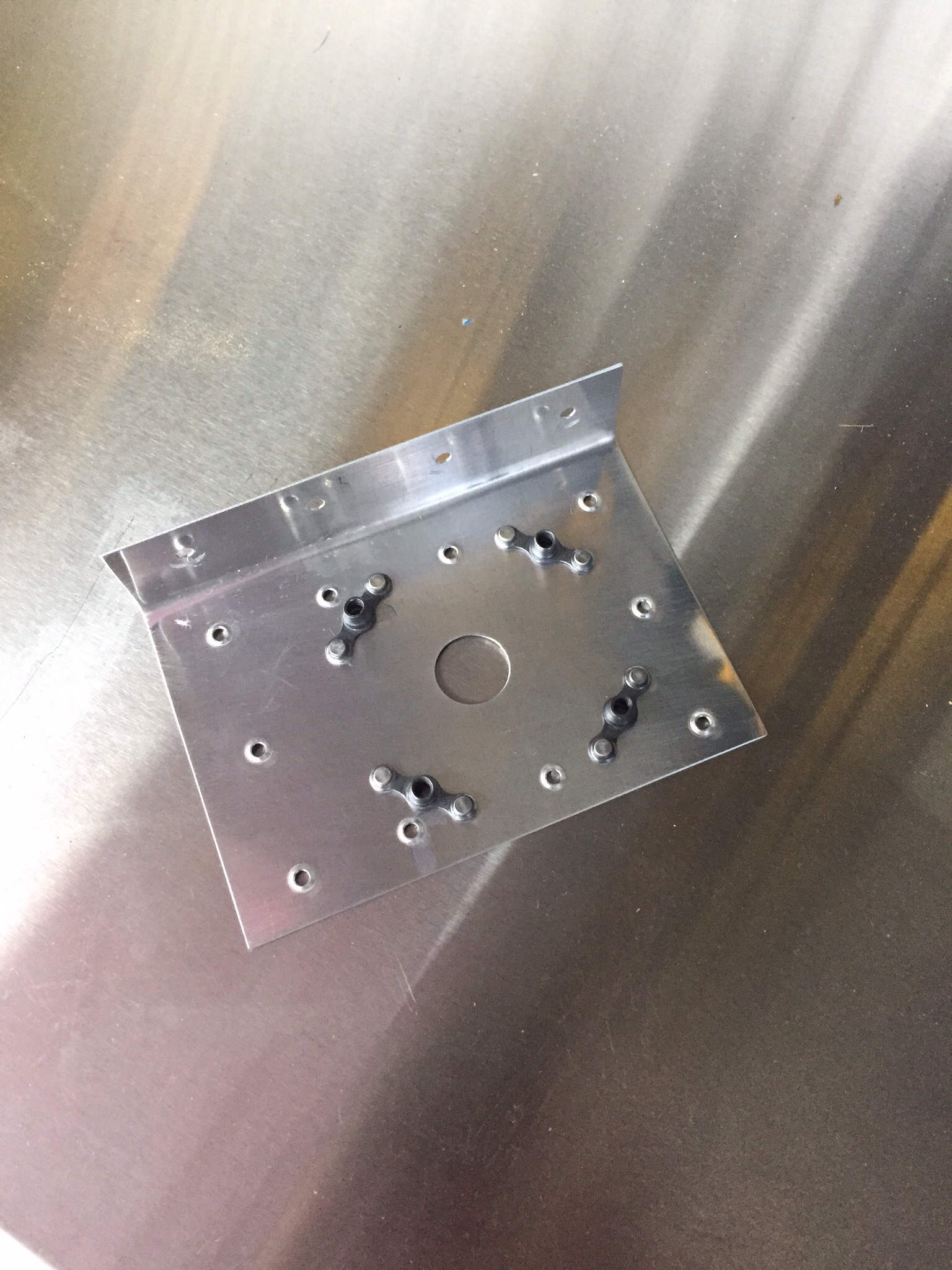
I also made up a couple of doublers for the comm antennas mounting on the belly.  I’ll be using Comant CI-122 VHF antennas and went ahead and installed nut plates since there won’t be acces from inside once the baggage compartment floor is in.  The doublers will tie into one of the baggage compartment floor ribs.  I will make two more doublers for the Delta Pop ADSB and transponder antennas which will go in the tunnel.


A lot of riveting evenings later, the skins are on and I’m ready to move on to the steps and pretty soon the tail cone.