Fun with electrons

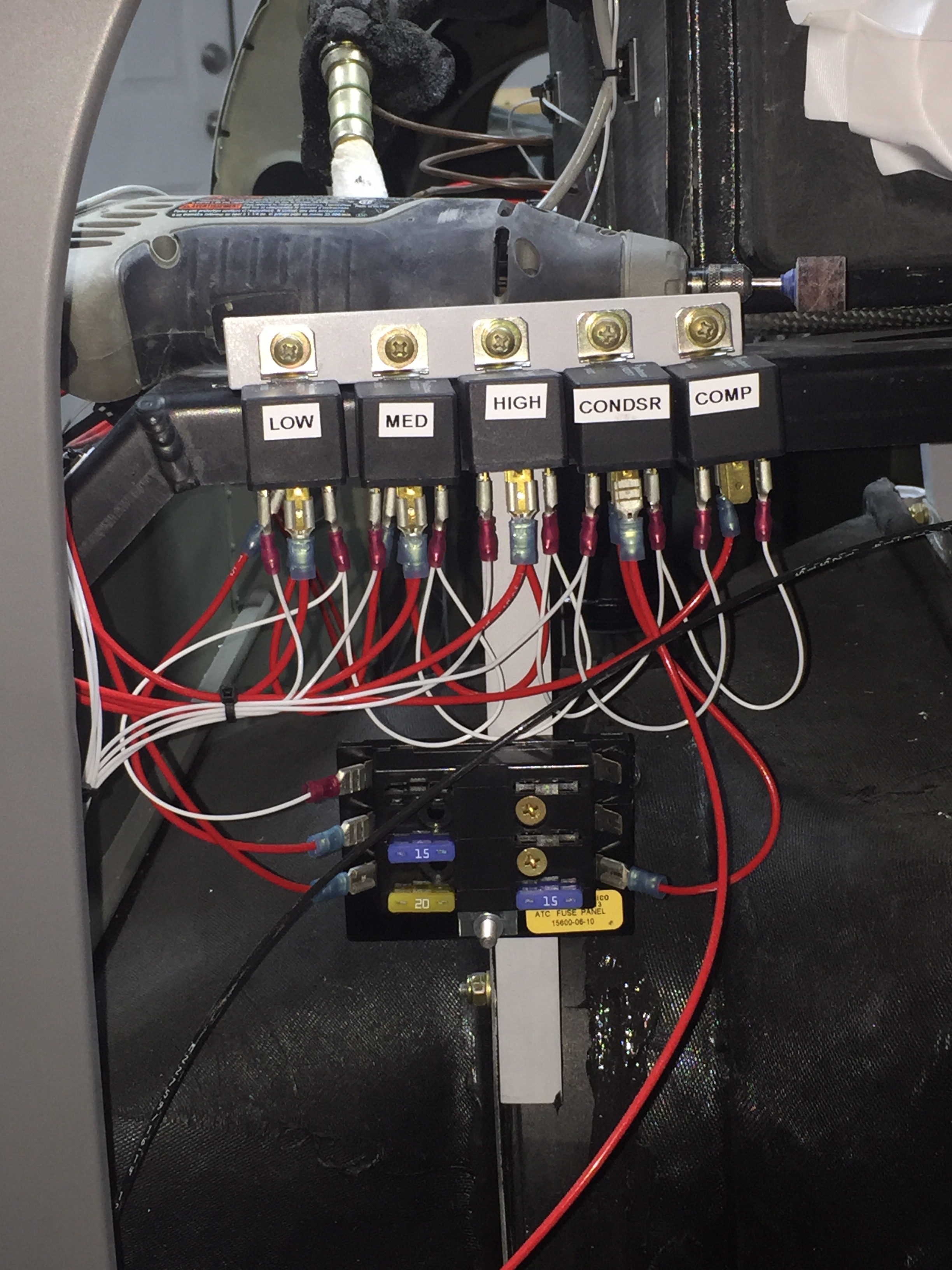
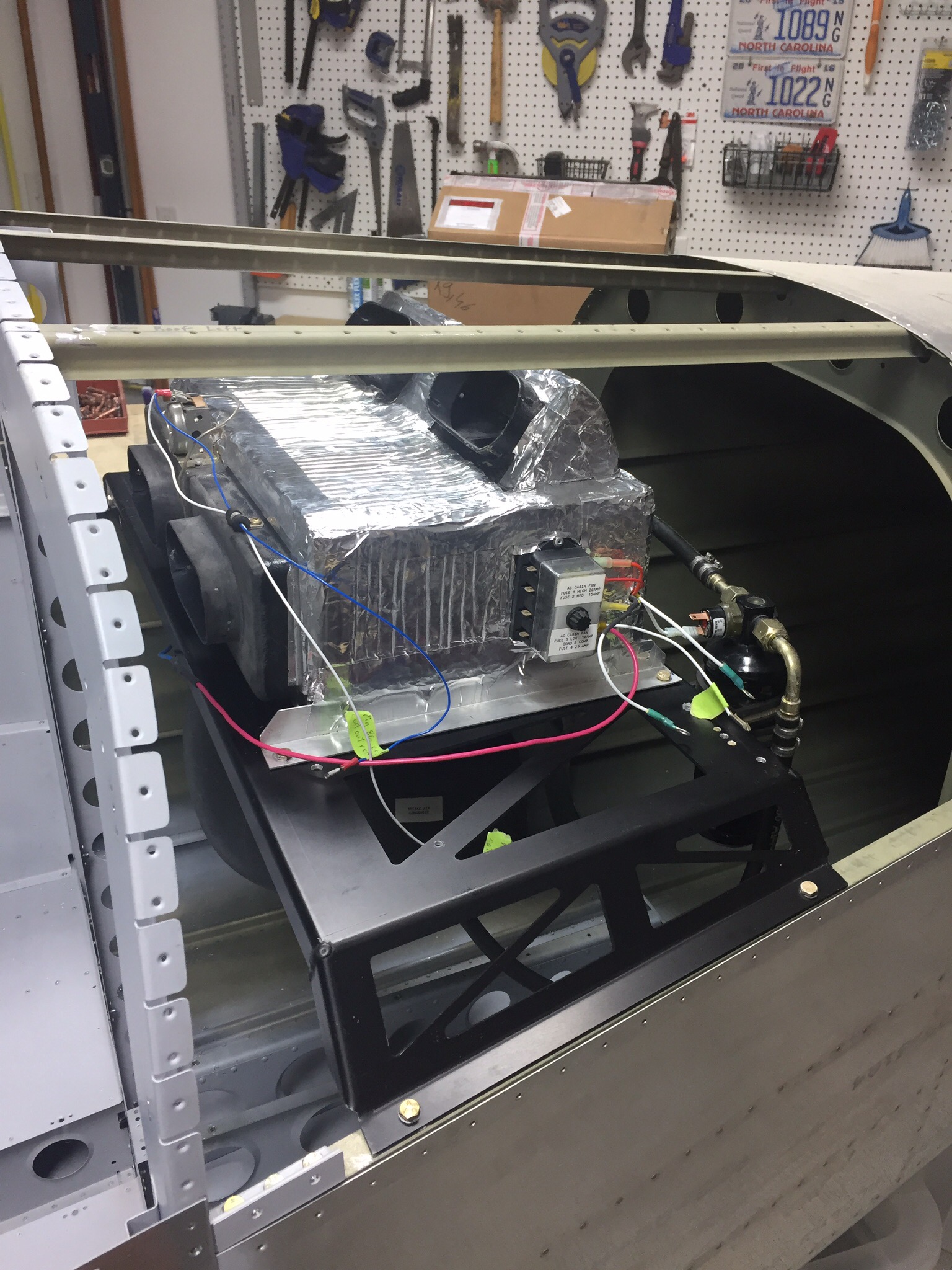
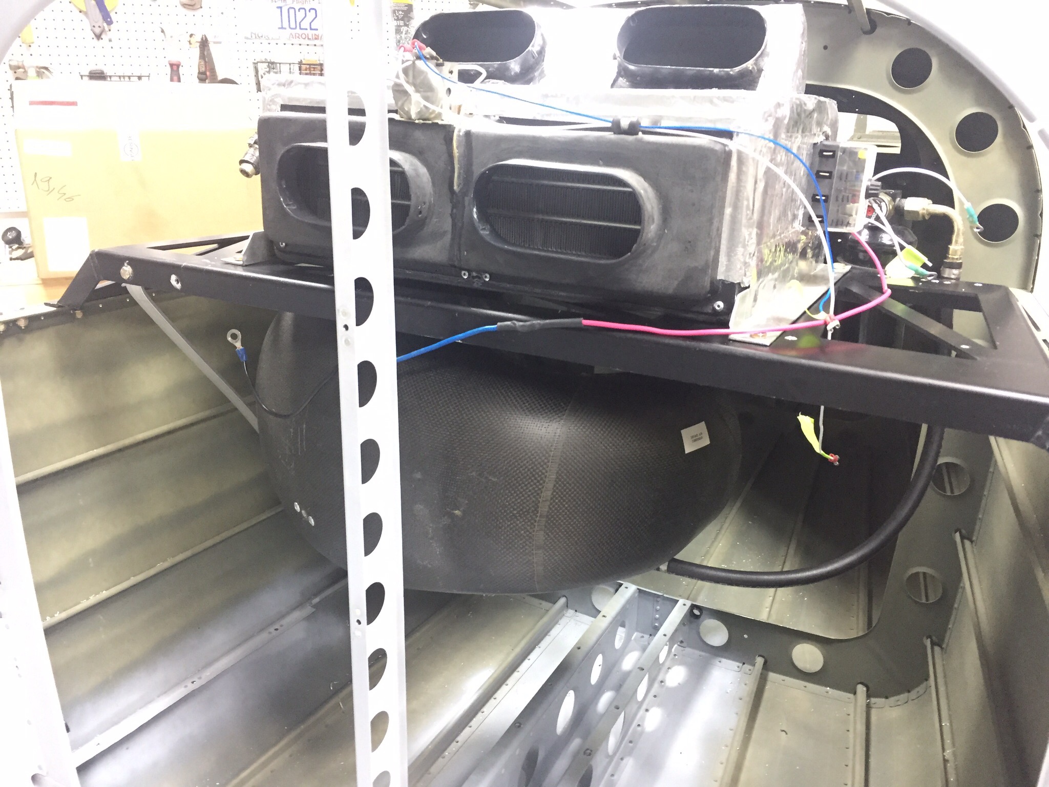
While waiting on the finish kit, I worked on a few electrical to do’s on the build. The AC system is installed, but all the wiring still needed to be hooked up. The system’s controller uses relays and I decided to move the location of the fuse panel to the bulkhead for easy maintenance. The relays were labeled and mounted to angle aluminum on the equipment tray. A lot of wire connectors later, the relays are all hooked up and the wires up front are pulled. I also wired the condenser fan with a disconnect for future servicing. The only wire not run is for the compressor, as I may go with an electric compressor depending on a few things down the road.

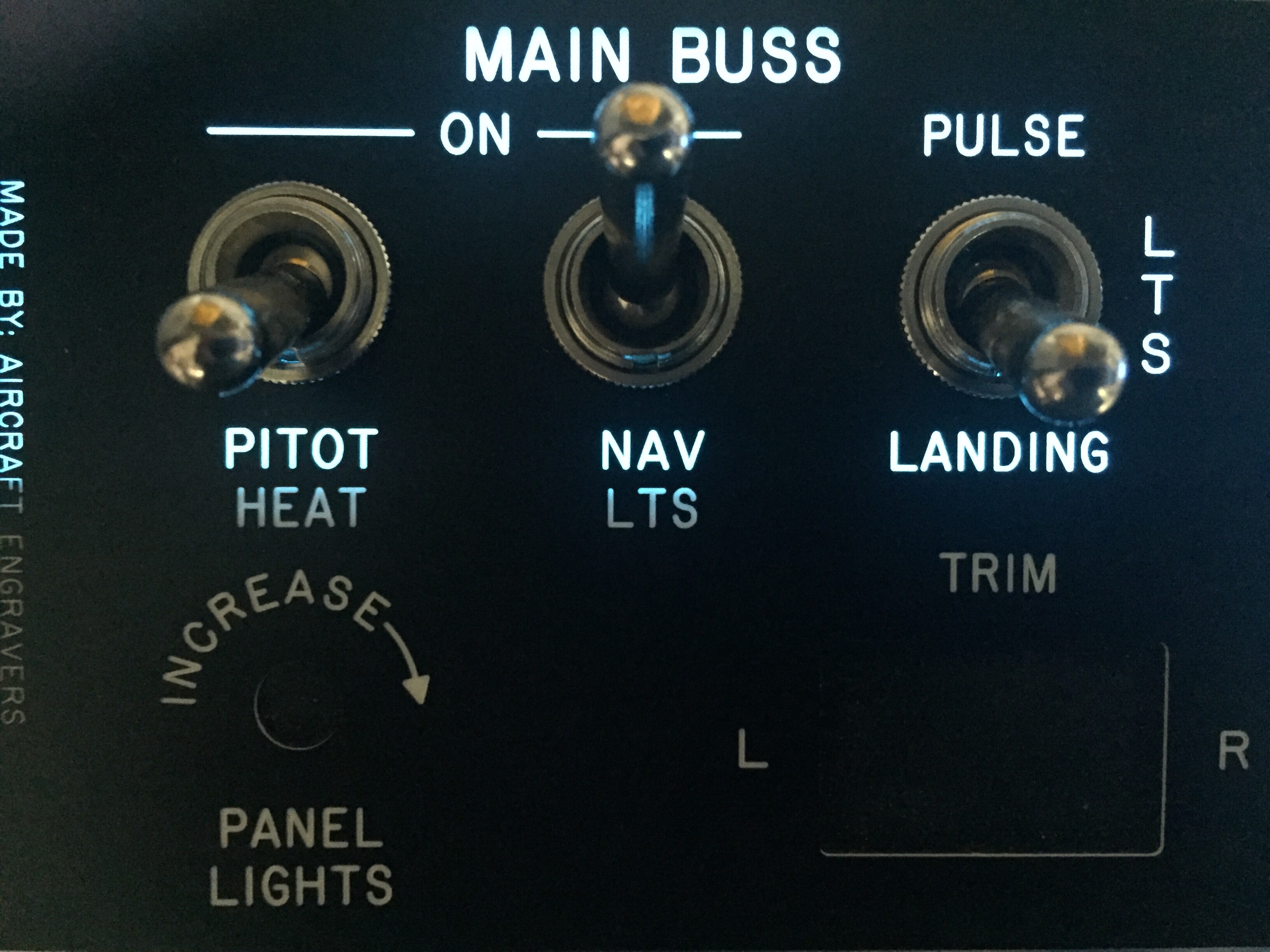
I also received a sample of the electroluminescent panel to experiment with backlighting my instrument panel. Aircraft Engravers sent me a sample panel on acrylic that I put on the EL panel and am really excited about the results. The EL panel put off a nice amount of light and dimmed well. The sample panel looked great and is easy to produce as well. My plan is to have Aircraft Engravers produce the panel overlays in acrylic which I will mount on top of the metal panel inserts holding the avionics. The EL panel will be sandwiched in between. In theory, it will be a nice clean look to the panel and have a high end backlight to boot. I took the EL panel with me in the Diamond on a quick flight to see if there was any noise from the transformer and didn’t notice any issues. Not a overly scientific test, but enough to keep me motivated to make this work.

I only had a 1″ strip, so you can see the difference where the panel is not backlit. The EL panel is also white when off, not the typical pinkish so the panel during the day appears to have white lettering as typical. More to come on this!

Full of hot air

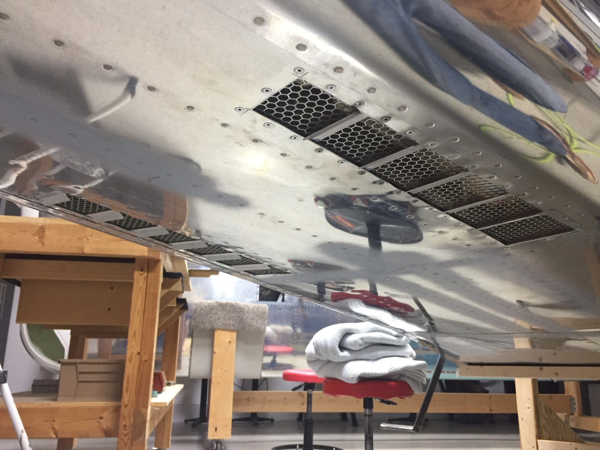
Anytime you have to cut a huge hole in the side of an airplane, your palms should start sweating. Mine sure did, especially since I’ve already cut two holes in the bottom of my airplane. Since the condenser duct system was cured and ready for install, I marked the exhaust cutout area got the Dremel out.
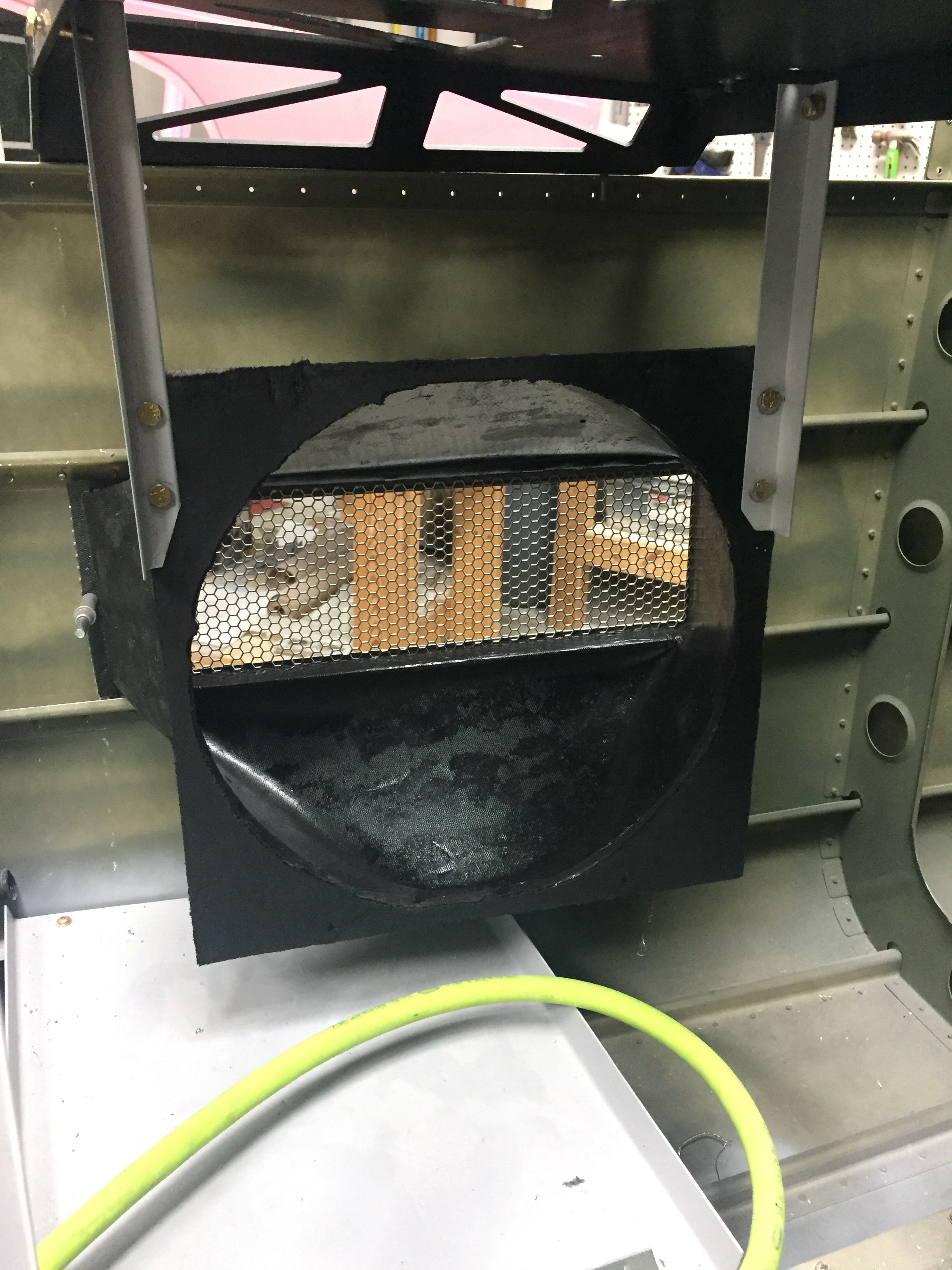
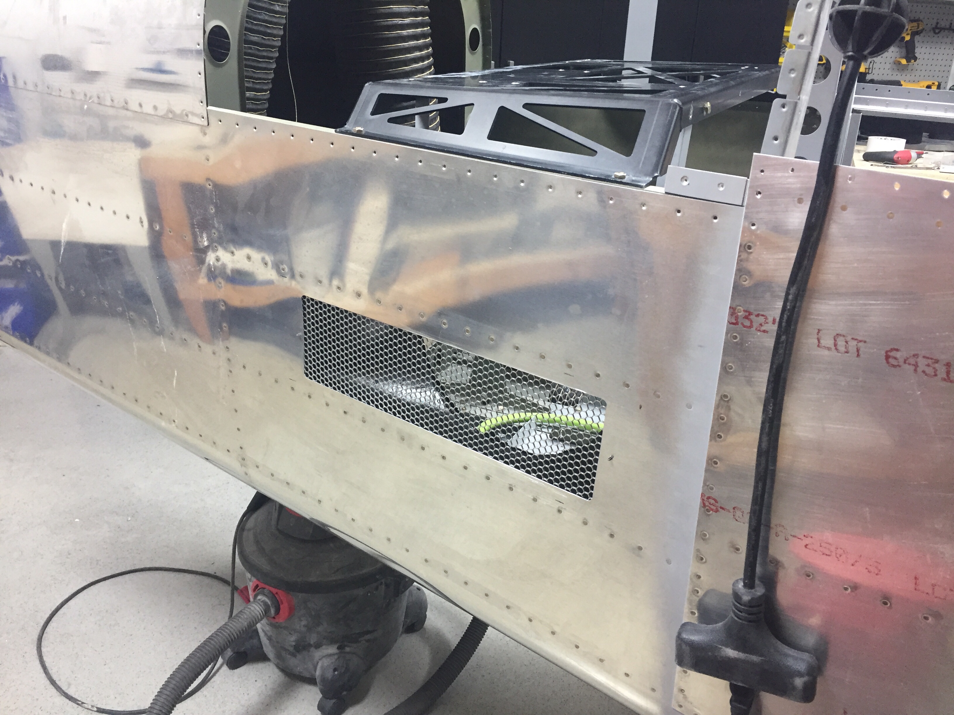
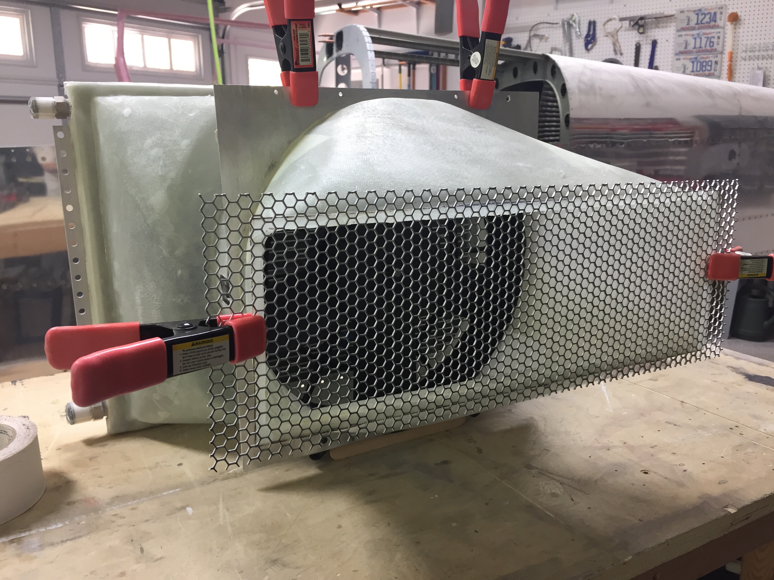
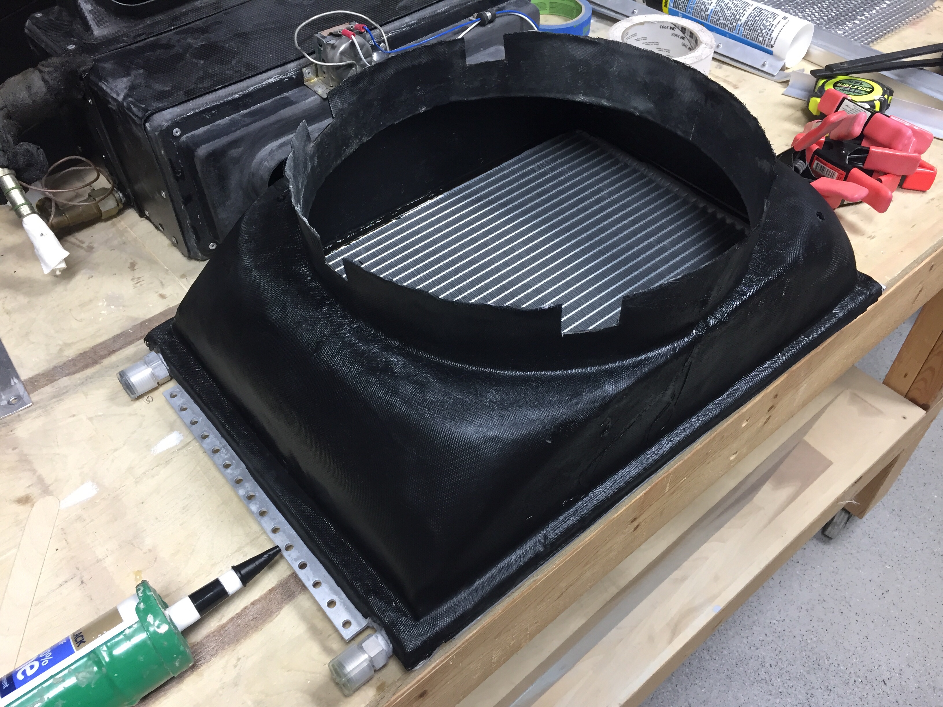
I had already ordered some auto grille material that provides some debris protection while allowing good air flow from the fan. It’s very similar to what Beechcraft is using on the Bonanza. I spray painted the plenums to minimize cosmetic issues once the plane is all finished. I used flox to epoxy the grille and duct onto the skin, making sure the grille didn’t have any extra epoxy on it. Once that was all sorted, I got the fan mounting plate hung via angle pieces to the AC equipment tray. The fan bolts to the mounting plate which is sealed to the plenum with a gasket made of neoprene, so the fan is replaceable and will also allow me to block off the fan during final paint.
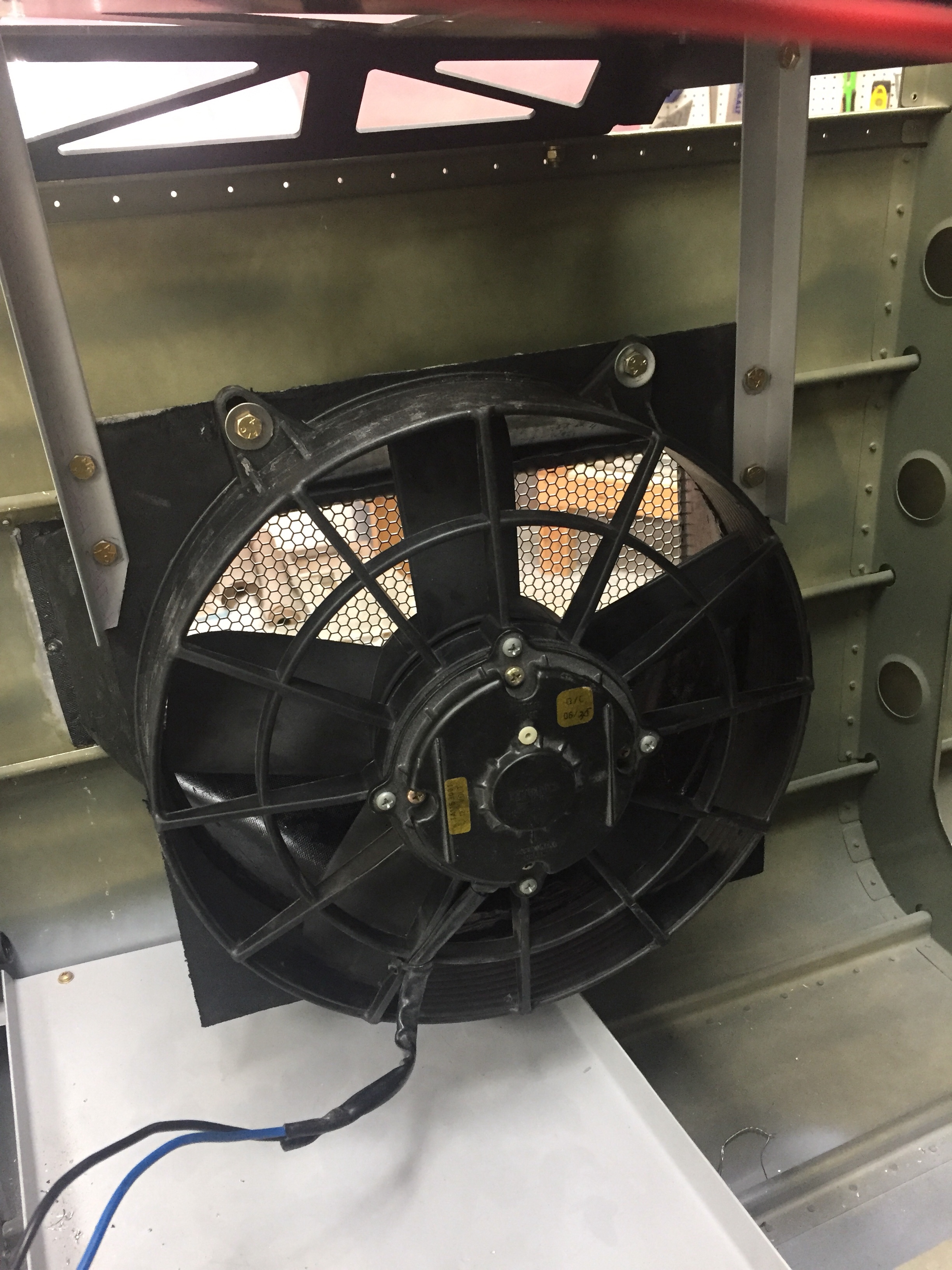
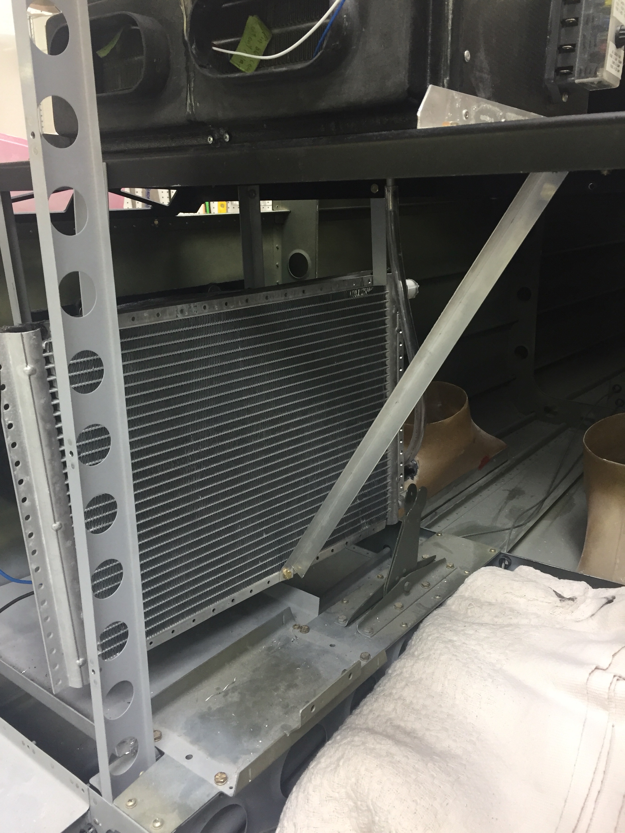
Next is the condenser to fan plenum which I sealed to the condenser with silicone. This slides over the fan frame and is sealed with a small bead of silicone around the seam, keeping the air moving where it should. The condenser also hangs from the equipment tray and has a flat stock support bar that keeps it from swinging. Once it was all together, it was very stable and will still allow a very tight, but passable cavity for me to crawl into the tail cone.
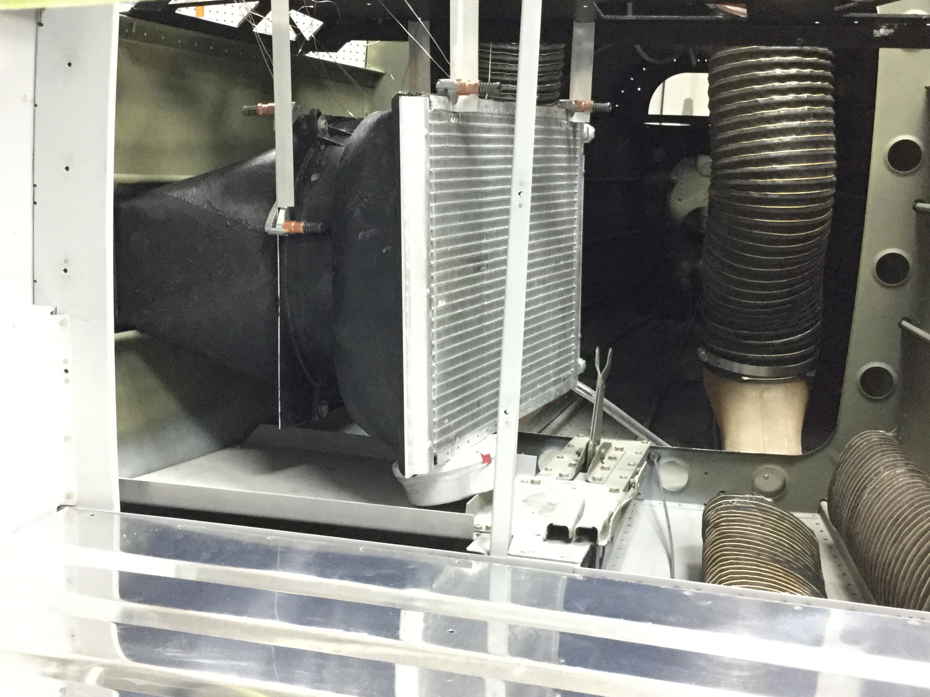
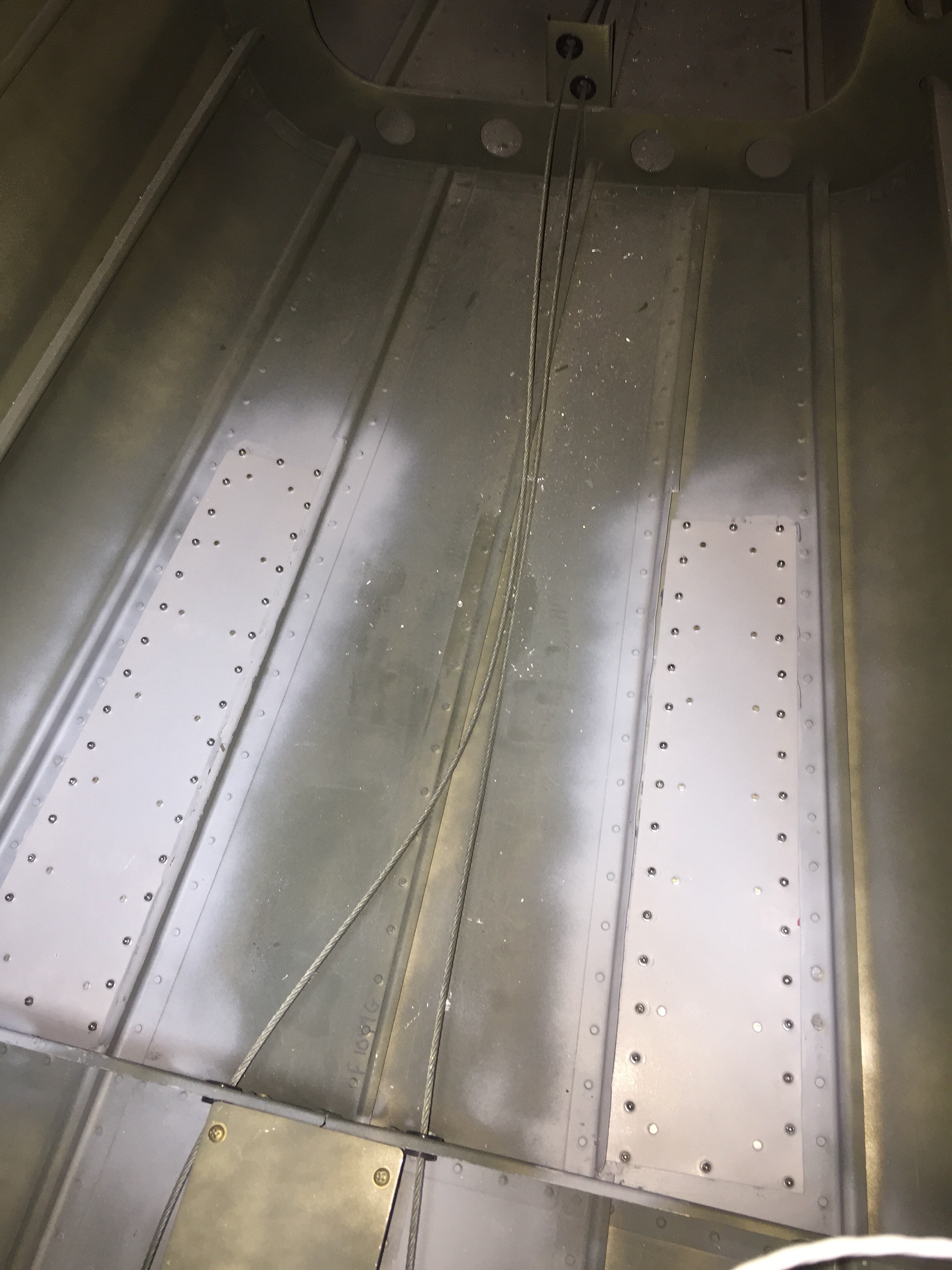
The clearance between the condenser and the pitch torque tube and pitch auto pilot servo is tight but it does all fit with no interference. With all of the equipment and exhaust ducting in place, I need to supply a fresh air source. The stock setup used one of the ducts you can see in the floor of the tail cone above, but they scooped air out of the exhaust heavy airstream. Again, like factory setups, I decided to have a vent on the opposite side of the tail cone with some small louvers just forward of the horizontal stabilizer. If any moisture does come in, it has an easy way out around the tail tie down and won’t affect electronics either.
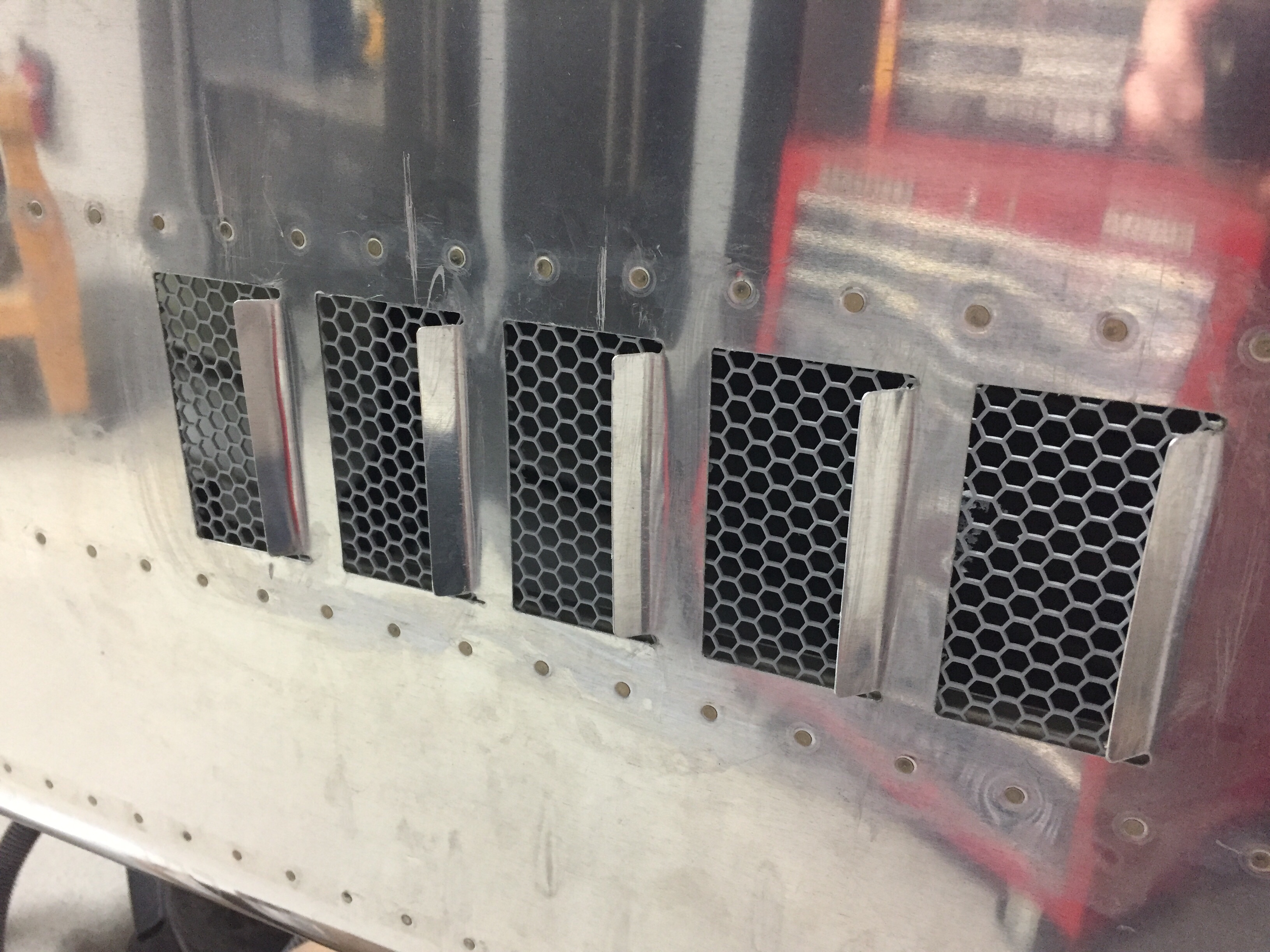
I kind of wish I had put louvers such as these on the exhaust side, but they’d be pretty easy to add later if needed, so I’ll add them after flying if I have any issues. The same grille material was epoxied in using a flow mixture that was used for the exhaust grille and plenum.

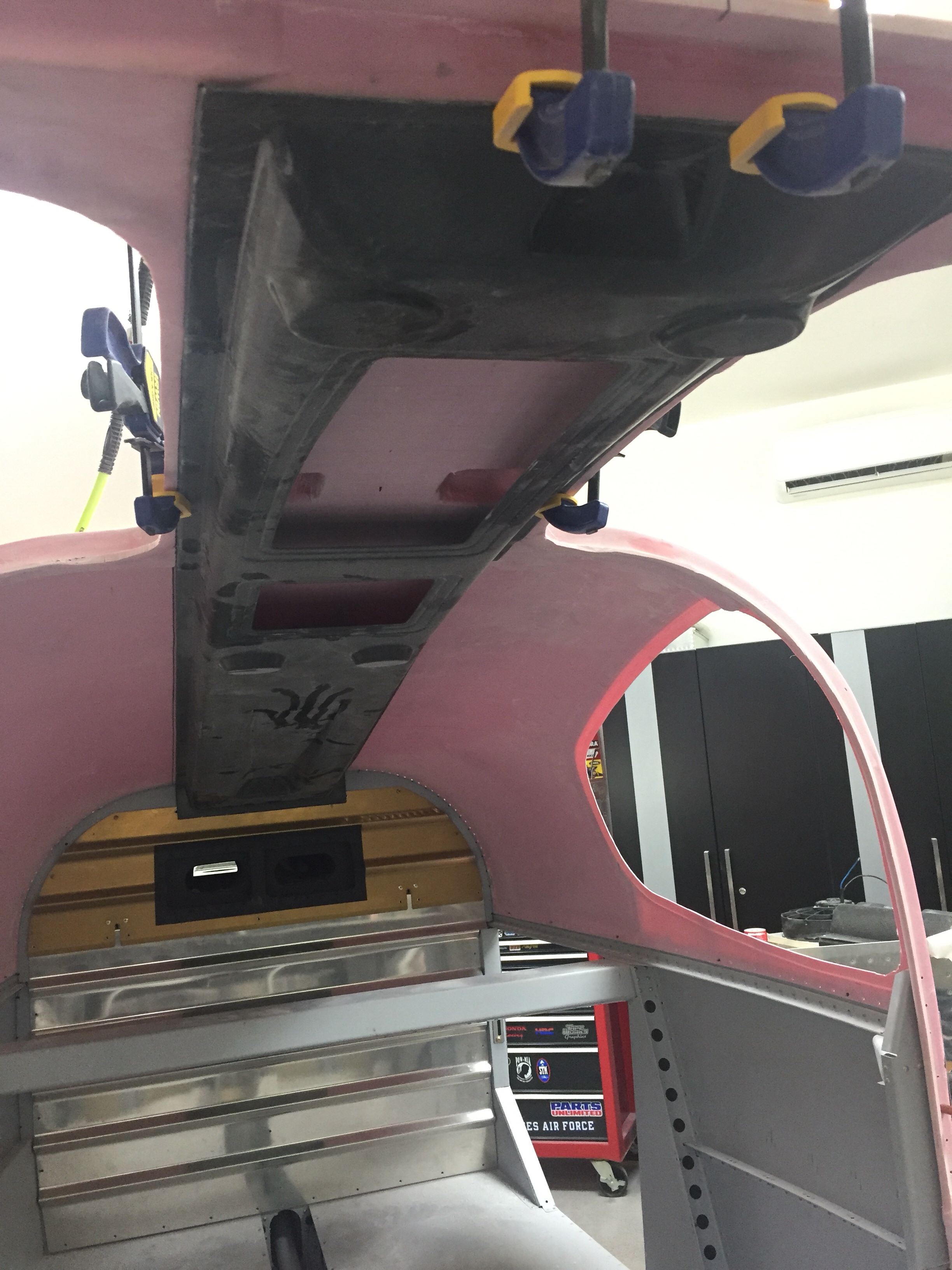
On the cabin side of the system, I cut the holes for the supply ducts into the baggage bulkhead and epoxied the duct shells into place. These line up into the Aerosport overhead console and the return air for the evaporator will go through the bulkhead itself as I am reusing the original owner’s setup and will have a faux trim covering the bulkhead to dress it up a bit.
Since I had taken everything else apart, I tore into the cabin fan box as well just to see what it looked like. It’s a pretty simple system but seems to work well. One thing I did notice was the fan speed control having four speeds. The wiring was to the low, medium, and high speeds with the max being unused. I decided to slide all three to the right so the speeds are med, high, and max which should give even more airflow out of the vents and through the cabin.
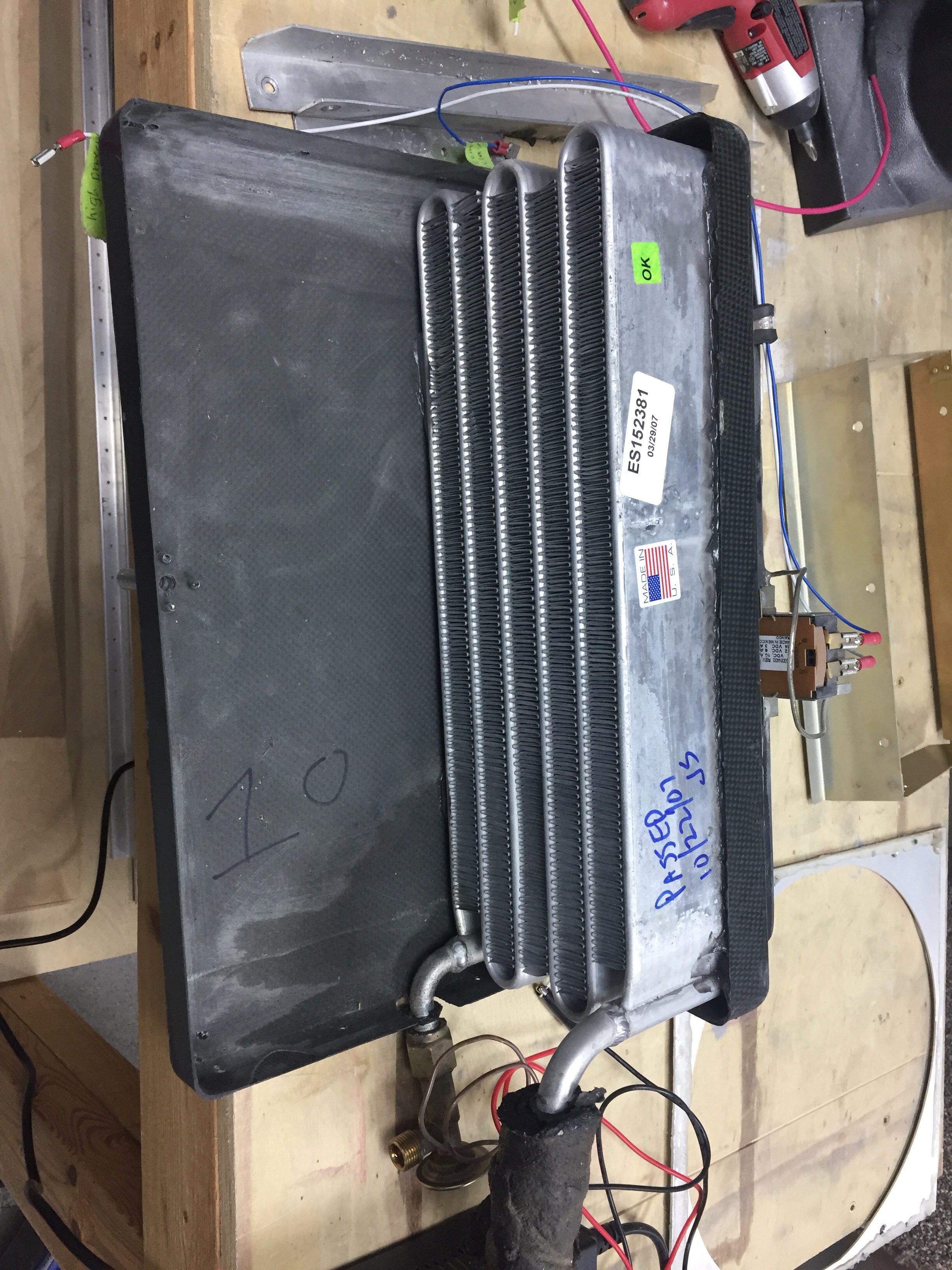
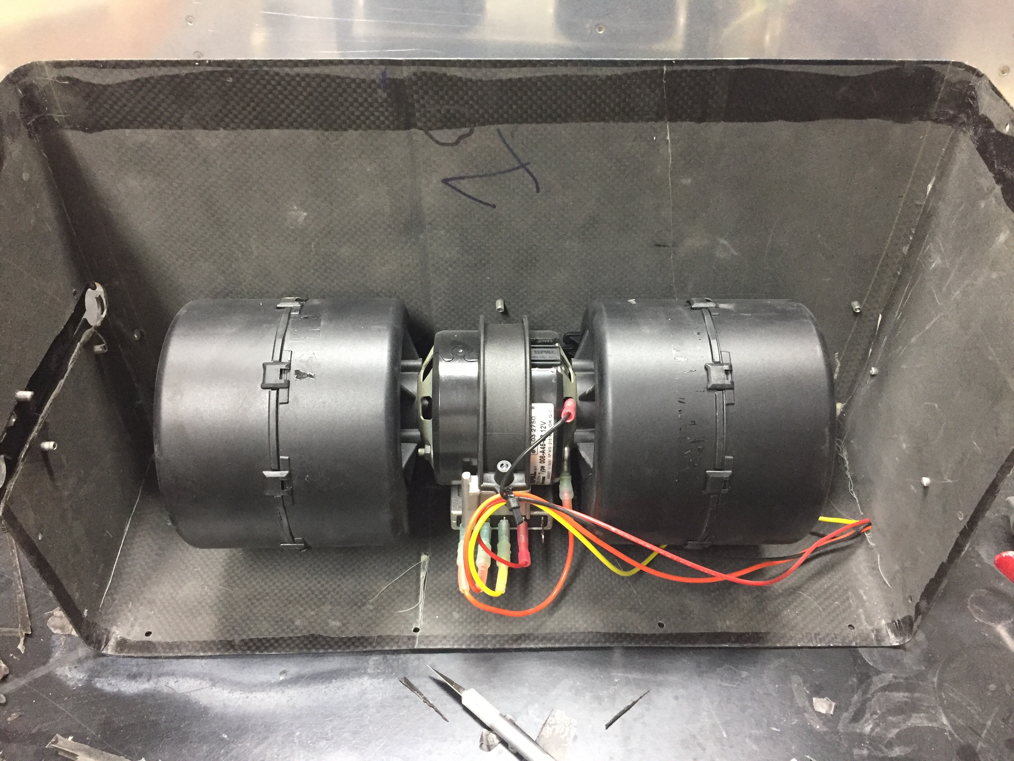
I took some extra time to silicone seal the assembly back together and made sure it was nearly air tight once complete again in the effort to increase efficiency. The equipment tray already had the mounting provided, so it was bolted back in and I went to work putting the flexible duct to the bulkhead supply duct headers.
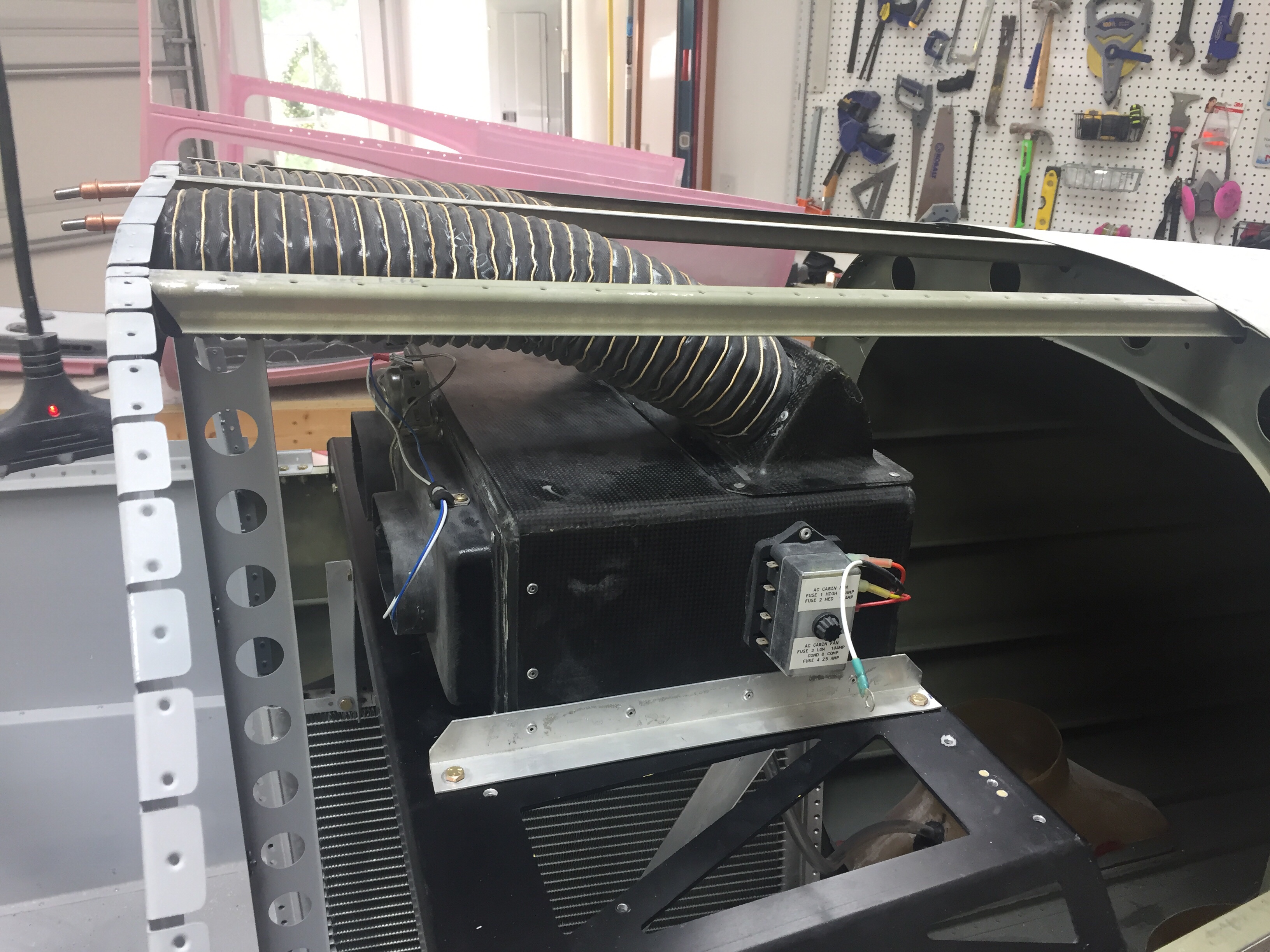
I’m ordering some thin worm clamps to clamp the ducting to the headers since the zip ties don’t really create a good seal.

After all said and done, this was a lot of work but it wasn’t terrible work. I’m very optimistic that the bones of the system will now work even better to provide cool air to the cabin and minimize the amount of attention the system will need over time. I still need to run the electrical and refrigerant hoses, which I’ll cover in a later post.

On a side note, I am still knocking little jobs off of the list such as the rudder cable fairings on the tail cone and a few other mundane tasks. Little bites at a time equal eating an elephant. Although you shouldn’t eat an elephant because you’d be a terrible person.
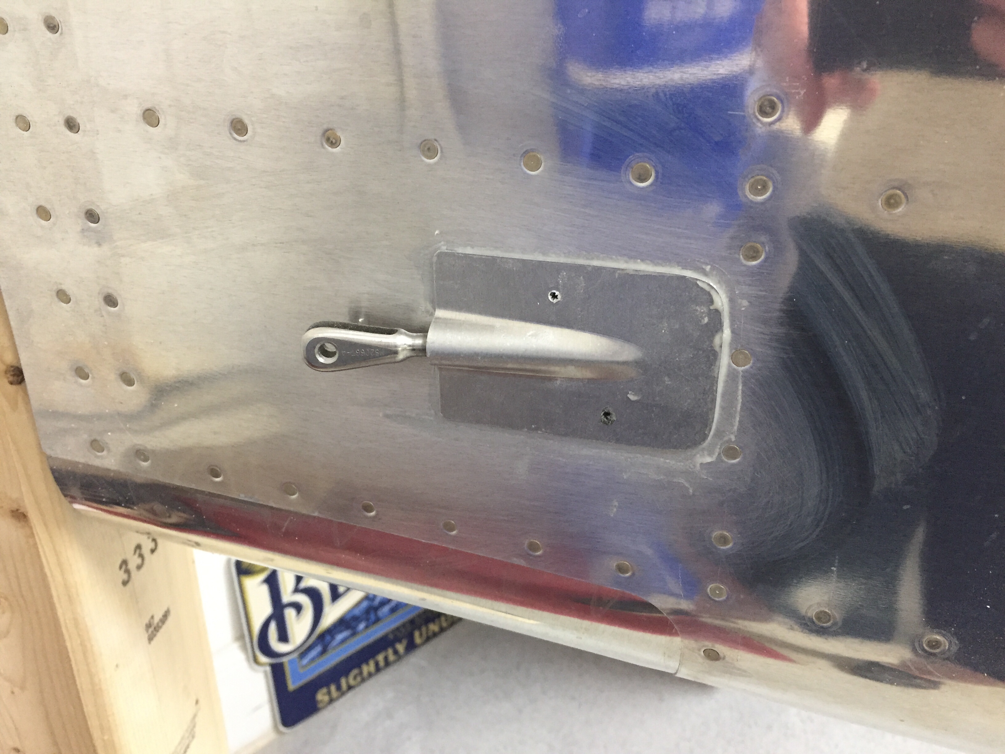
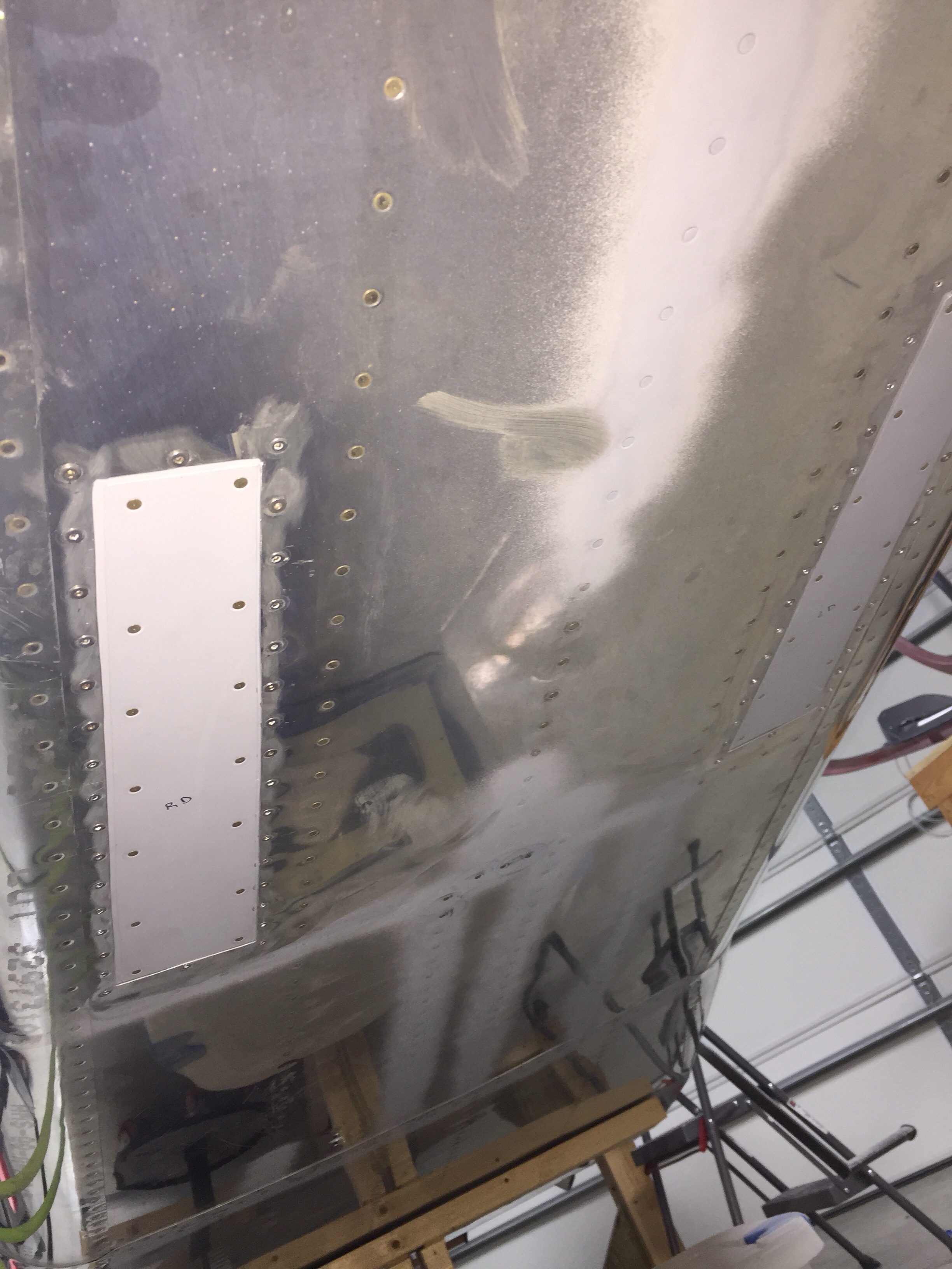
I also took out the stock intake and exhaust vents for the air conditioning and patched them using the original skin and backer plates made from the trim kit. I’ve finished that up by putting some filler in the cracks and smoothing it all out. It’s not perfect, but good enough for the bottom of the fuselage. If you’re judging my plane that much, you better have a rag and cleaner to wipe it down while you’re under there!
So I changed my mind, cool it.

I’ve been doing a lot of research and discussion with folks who have installed air conditioners, especially the Flightline setup like mine. The general consensus is that it’s marginally effective at best. My standards aren’t extremely high, as the AC in the Diamond we fly just takes the edge off but doesn’t really cool like a car would. Others with the Flightline system have added a second condenser and one or two have routed the intake from the bottom to the side skin to avoid the exhaust mixed heated air. As my original commitment to John at Flightline was to design a side intake and exhaust, I decided to dive in and redesign pretty much the whole dang thing.

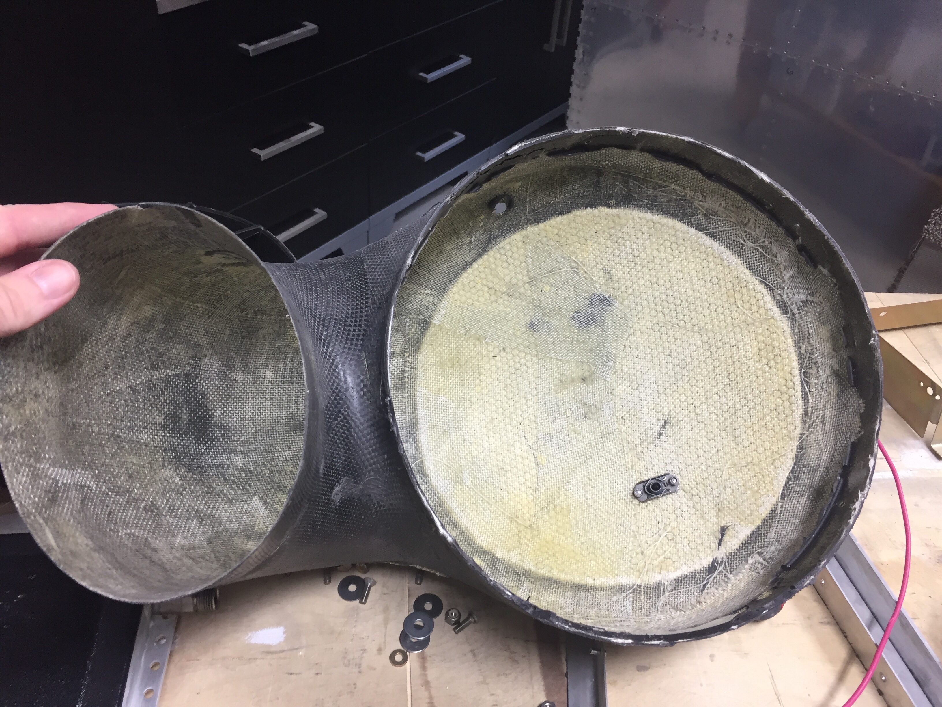
First, an overview of the setup. An intake on the bottom tail skin catches air and directs it through 6″ flex duct up and 90 degrees forward where it turns 180 degrees and goes through a 12′ square condenser. A 12″ puller fan helps air flow volume so it doesn’t rely solely on ram air pressure. Then, it heads back into a 6″ flex duct, makes another sharp 90 degree corner and exits out the bottom skin. It’s a lot of direction changing and restricting of the air.

I began by taking everything apart and checking out how it was all pieced together. The first thing I noticed was the mounting plate for the fan actually covered a 1/5 or so surface area of the condenser. Additionally, the system didn’t use basic air velocity and volume principles, so it was constantly going from small to large volume spaces with many restrictions.

My goal was to facilitate air flow through the shortest path with the least resistance, thereby providing more efficient flow and better heat exchange in the condenser. I studied several factory AC setups such as the Cirrus, Bonanza, and M350 and noticed no ducting on the intake and direct exhaust from the condenser through the skin. The condensers were also significantly larger in surface area. So the new design would be to pull ambient air from the tail cone through a larger condenser via the same fan and exhaust it through the side skin within the shortest path possible. The ambient air is provided through an louvered intake near the horizontal stabilizer.

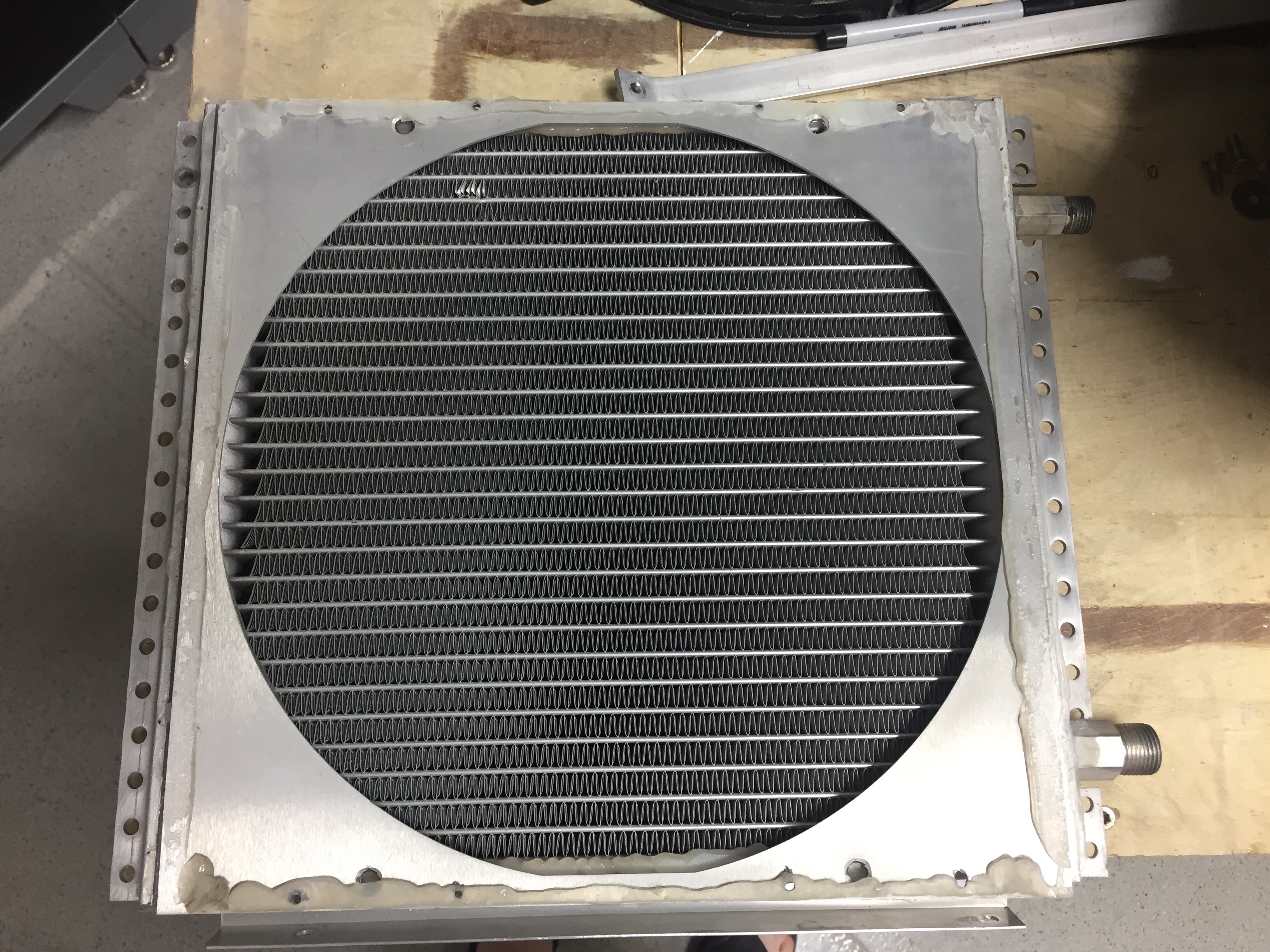
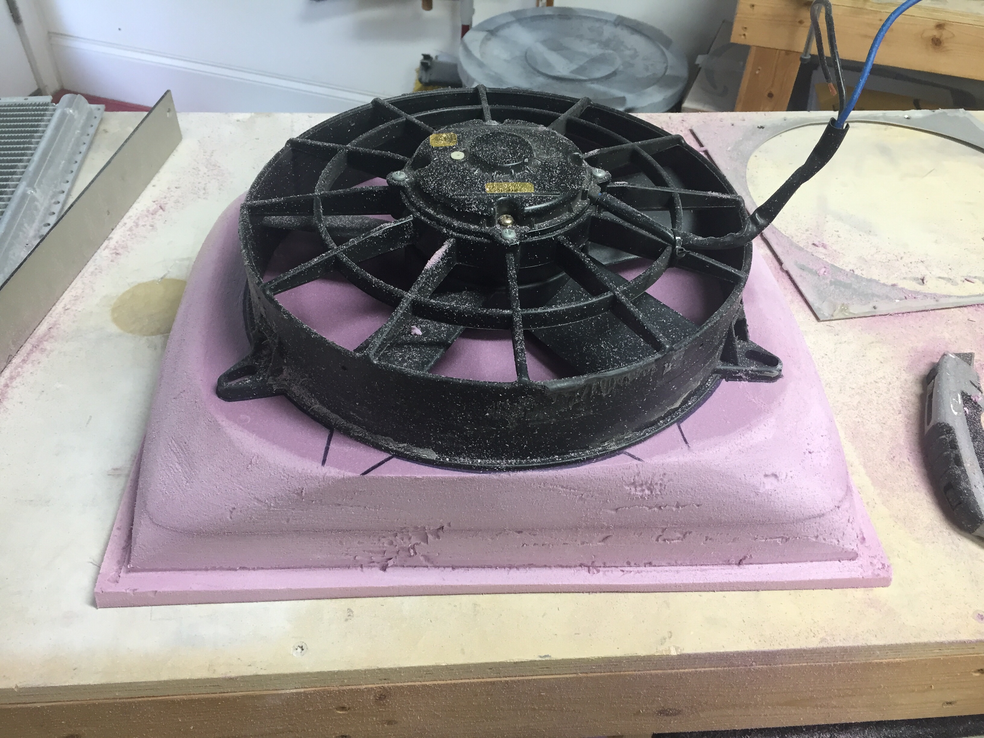
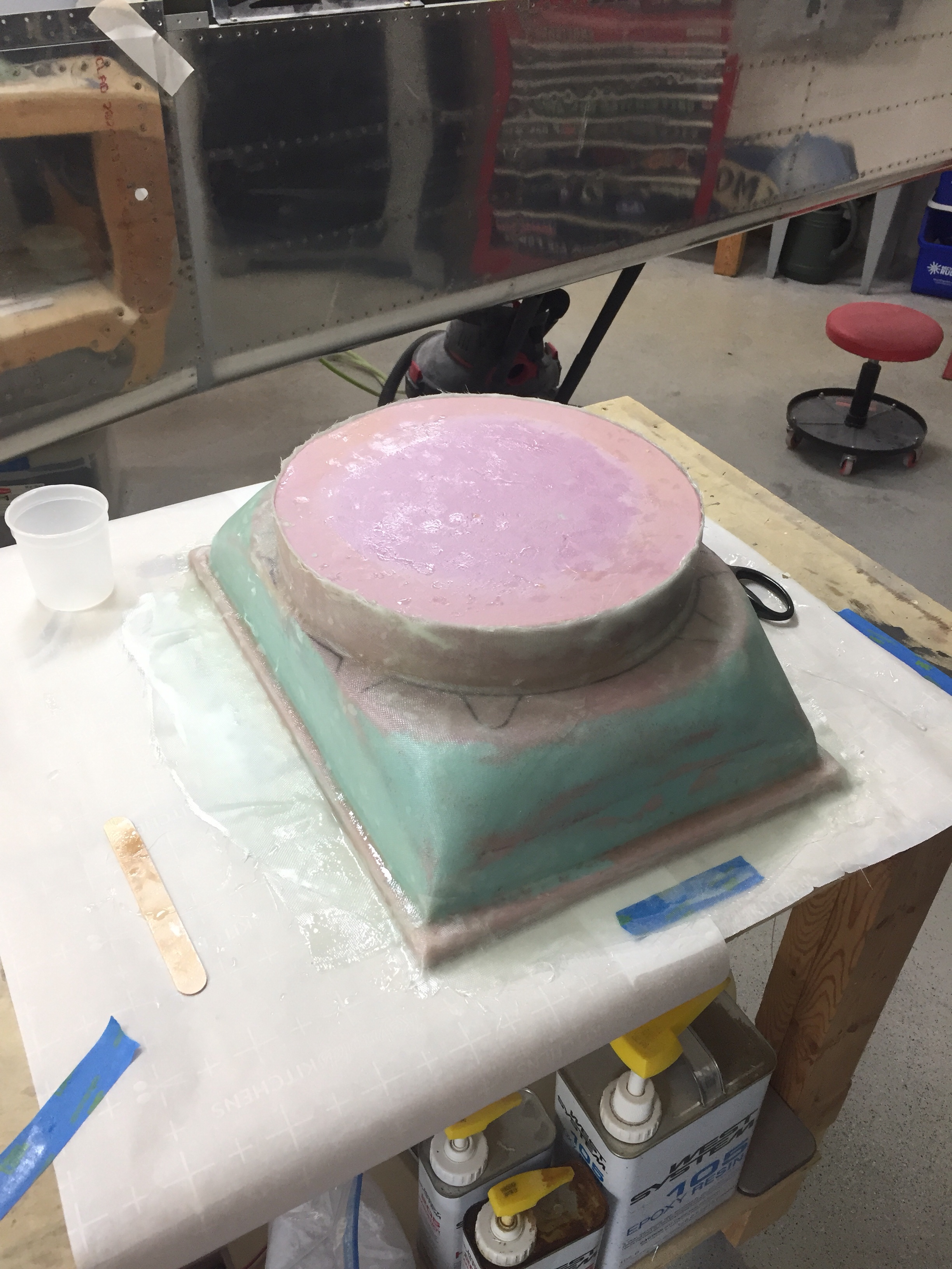
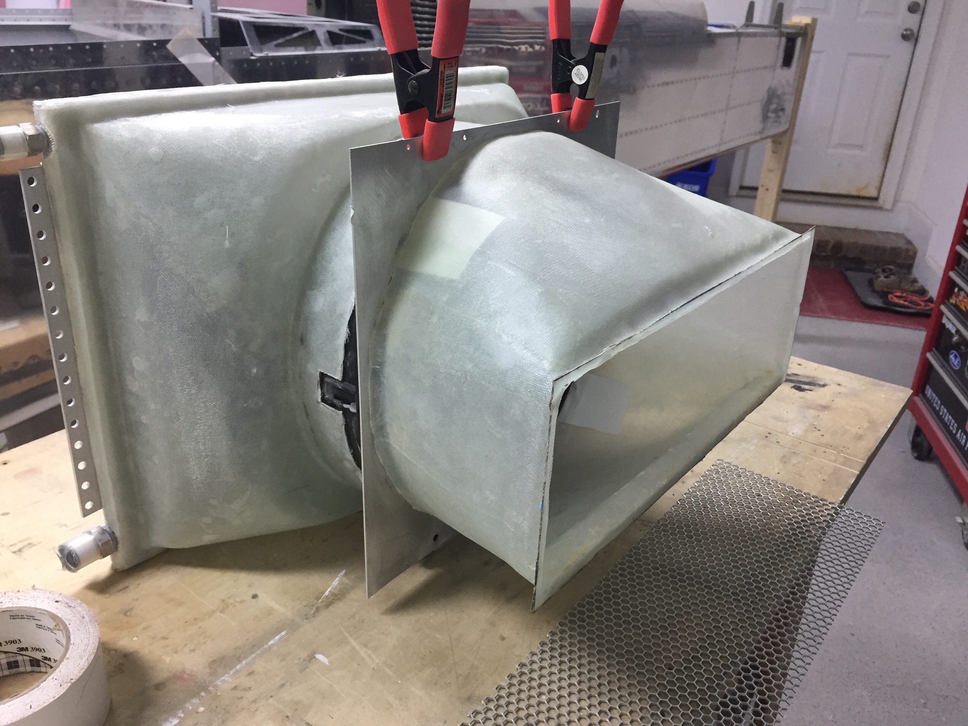
So, I bought a 16″ x 12″ condenser and set about molding a plenum from the condenser to the fan. If I had a vacuum table, this would have been perfect to keep the mold to share with others, but unfortunately I had to lay up fiberglass and the molds were trash.

The layup came out very nicely despite destroying the mold and was a perfect fit around the fan casing. A simple bead of silicone should seal it up nicely when installed.

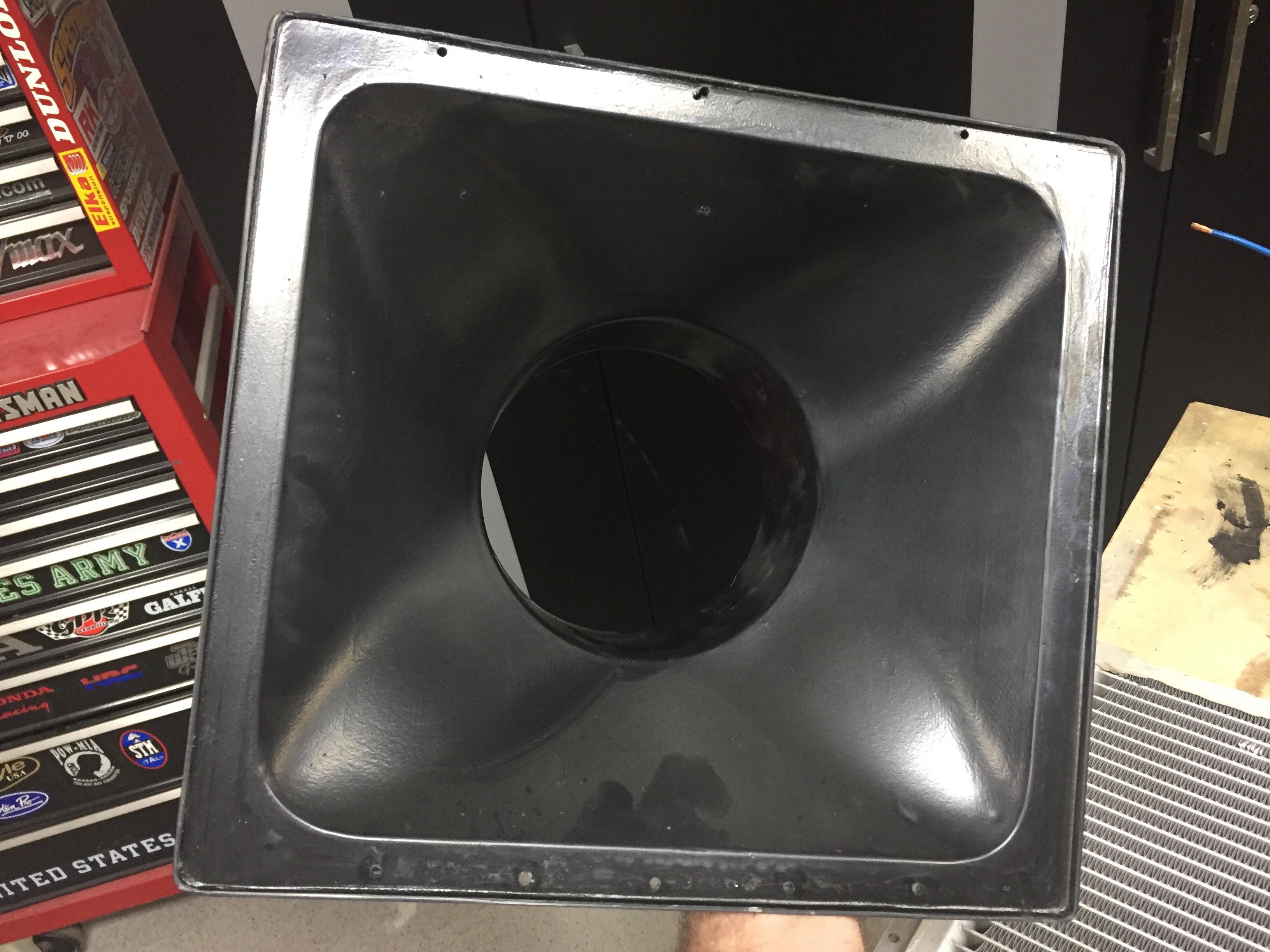
Next was to do a mold from the fan to the skin for the exhaust. I figured up the square inches of the fan and worked within the stringers to maximize the opening area while keeping it just under the square inches of the fan. My thought on this is using the Bernoulli principle and having the smallest (relative to the entire air path) opening creating the highest velocity at the skin. This will in theory help the exhaust penetrate the boundary layer air around the fuselage, which has also been a concern from others.

I used the same fan mounting plate since it’s no longer restricting air flow. The exhaust plenum as a lip molded in to use as a mounting surface on the skin. The weight of the setup will be supported from the stock tray so the plenums aren’t load bearing.

I put it all together and hooked up the fan to check it out. There is significantly more air flow going through and I’m cautiously optimistic that this will create a much better performing system.

Next up will be mounting it all in the airframe and cutting the skin.

Controlling the overhead

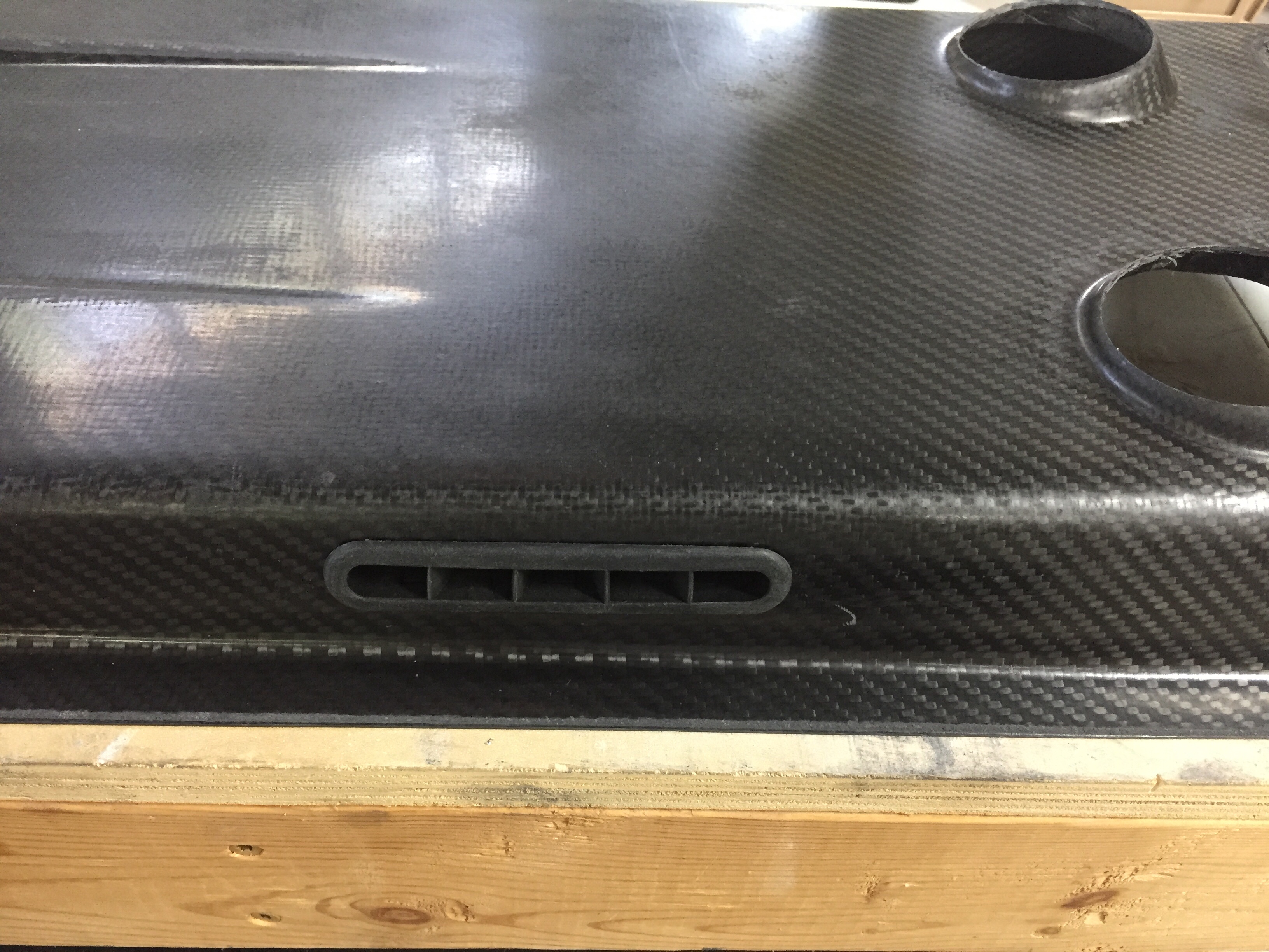
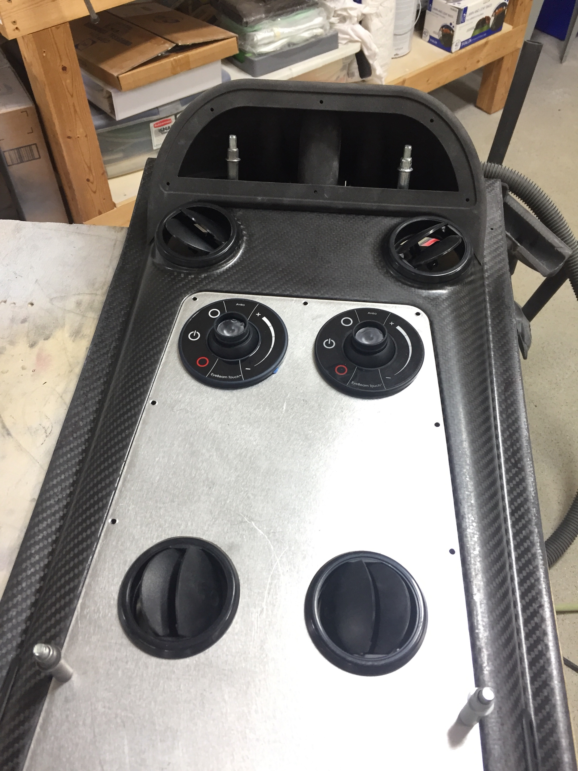
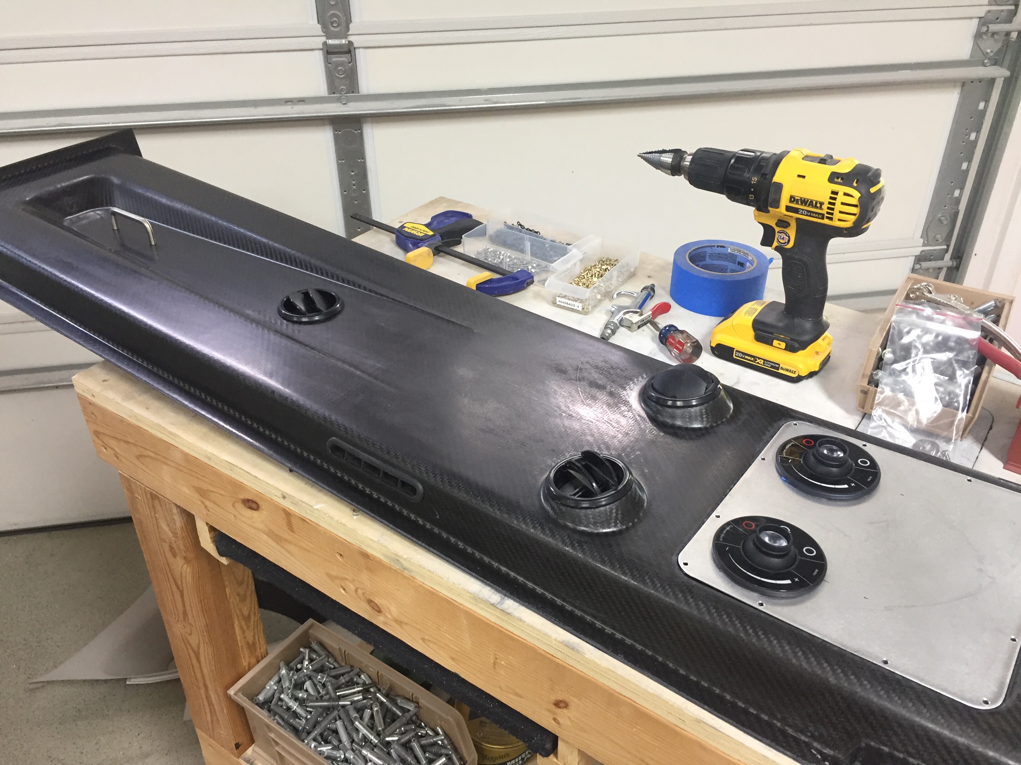
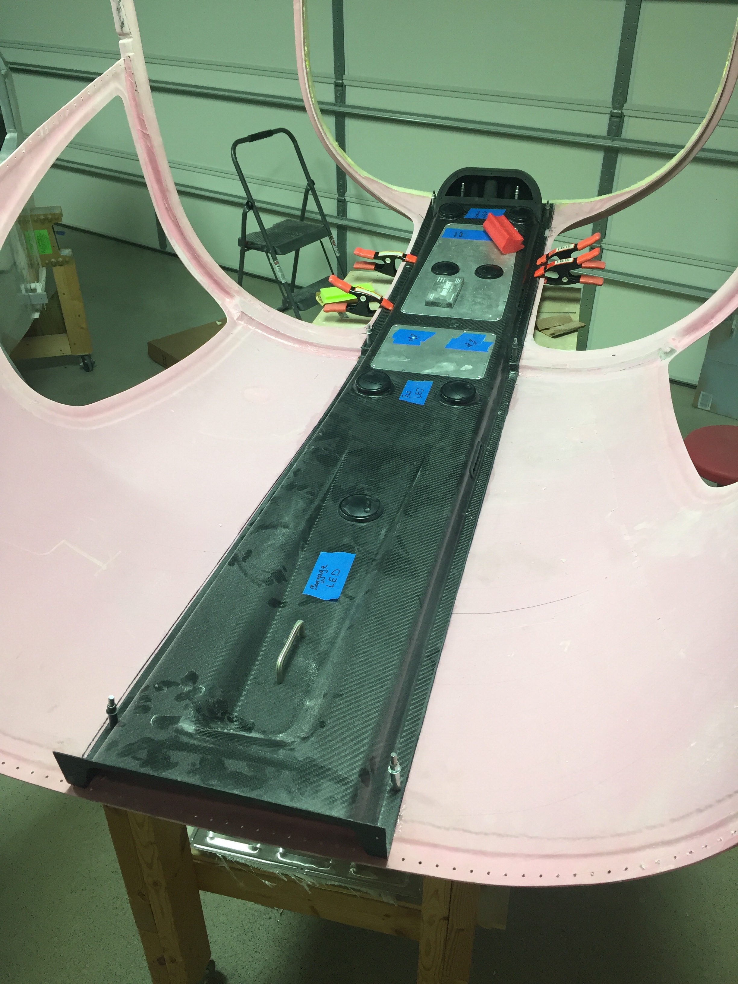
One huge task to complete before the cabin top can go on for good is the overhead console. This piece of art comes from Aerosport and allows the vents for the air conditioning and the lights to be mounted on the cabin top. I also have one of the first production examples of the overhead switch panel that Ed Krantz molded up.

The first step is a rough fit and trim to get an idea where the interference points are. The mold they use is pretty accurate but has a few spots that needs adjustments. I didn’t have to cut the joggle around the step in the cabin top, however, there were a few spots up near the windshield that were too bulbous and had to be ground down. Overall, the initial trim and sanding was a pretty quick and painless job.

The overhead has two large aluminum panels that can be used for lights, vents, etc. but need nutplates installed to secure them. Pretty quick job to set it all up including countersinking the panels for flush screws that came out very nicely. I also decided where to mount the four curtain vents that I got from South Florida Sport Aviation. They are using the Airflow Performance set up on their own interior and despite my best efforts, I couldn’t find any vents like these online. I like these because it allows good airflow along the windows as well as alternate airflow if one or more of the vents are closed, keeping good flow through the cabin and over the evaporator which is key to efficient performance of the air conditioner.

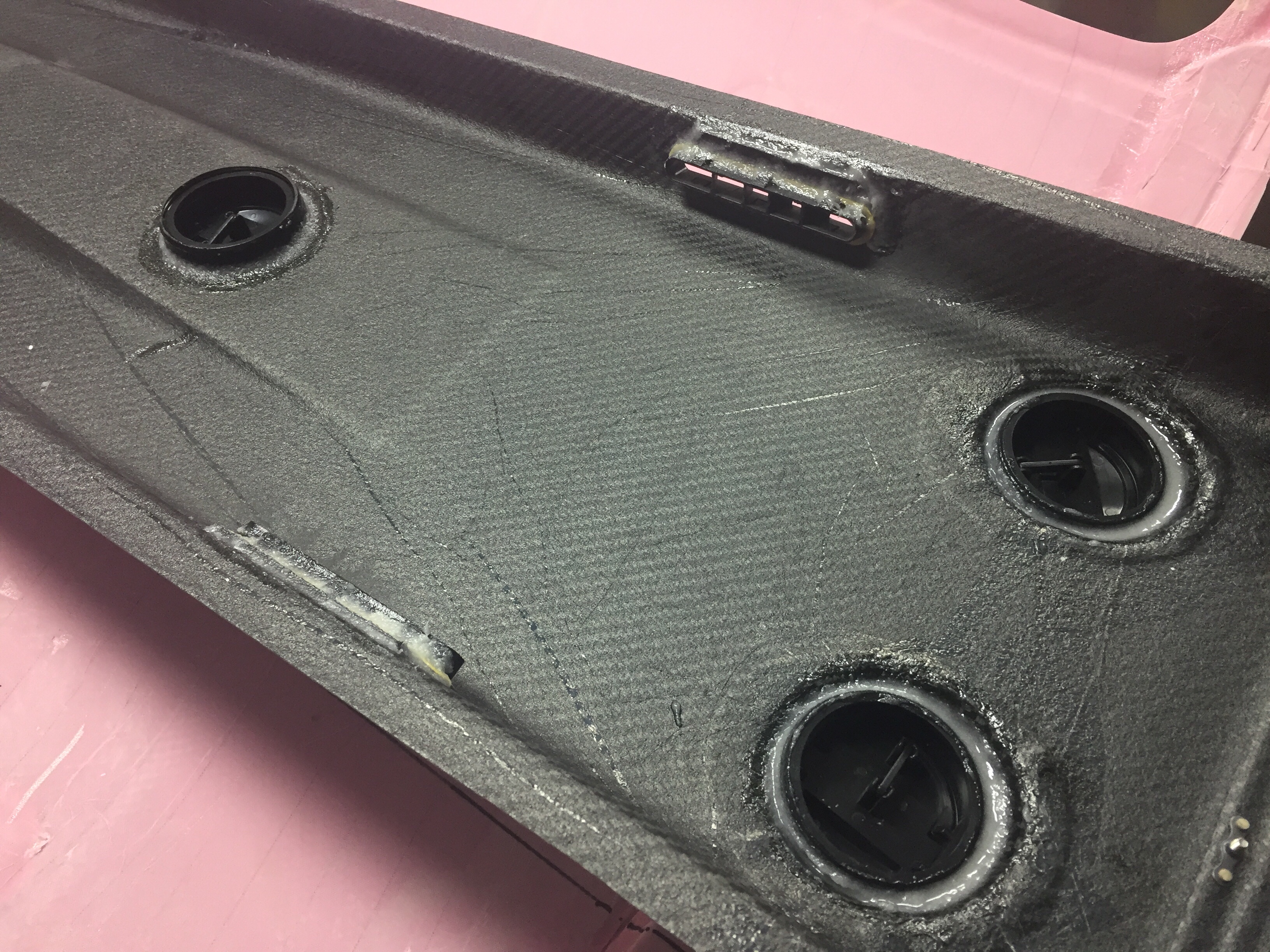
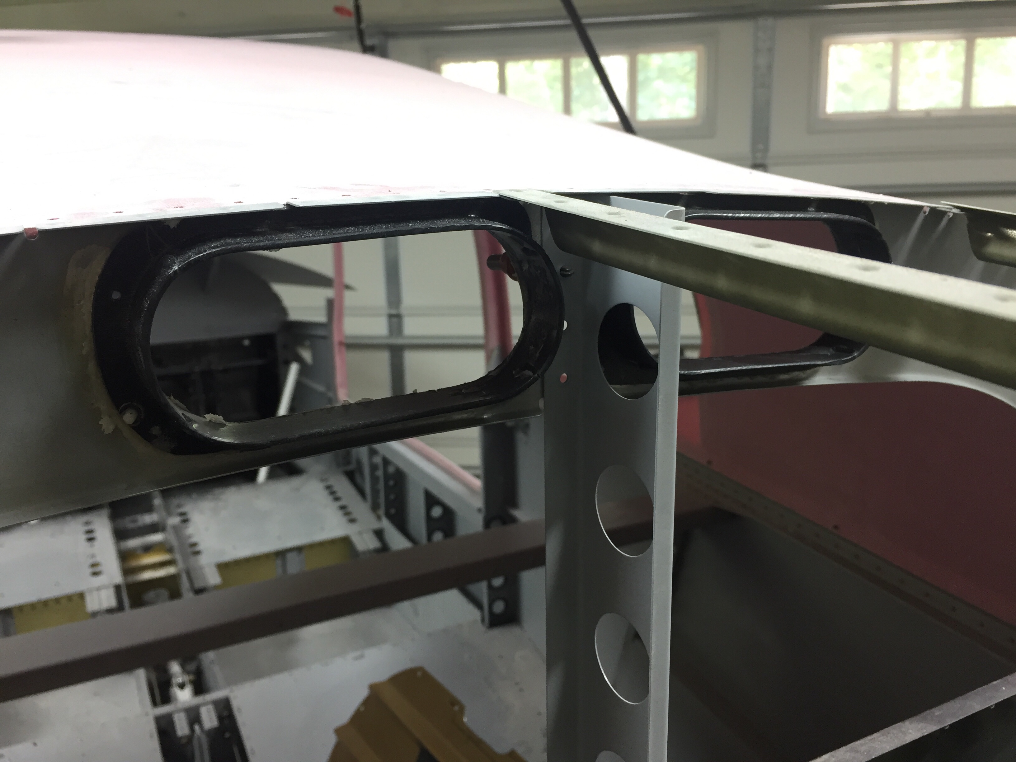
I also used the four molded spots to mount air vents in as you can see the cutouts above. Most have used either the eyeball vents or a universal car vent. Based on feedback from others and the astronomical price of eyeball vents, I decided Summit Racing vents would work better. They were $20 each instead of $120 each and I think will allow a lot more air to flow while being easier to use. I simply used epoxy/flox to secures them to the overhead taking care to not have any leak on the vents themselves. I also put two vents in the metal panel so that the pilot and copilot each have two vents, hopefully keeping me cool up front with all the glass. The panels will also hold an Aveo Eyebeam Touch task light for each seat.

Lastly, I installed the coat hanger in the rear which will probably rarely be used, but hey, it’s part of the kit and looks good. I can also use it to call this a business aircraft!

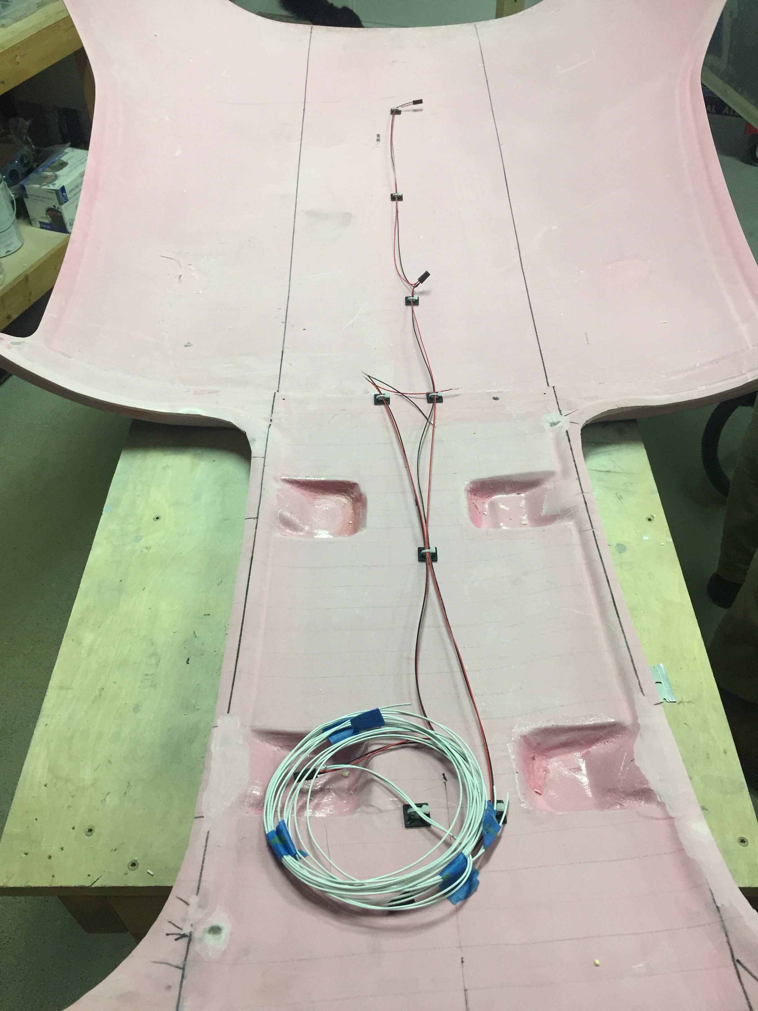
I will be running the wires for the switch panel and the task lights up through the center post so wanted to get the wiring that will be in the overhead completed. I went ahead and made up the wiring harness for the four task lights as well as the three overhead dome lights that will be used for general cabin lighting. The pictures show bare contacts, but after another order from Mouser came in, I installed the Molex connectors so that everything is line replaceable without cutting wires. I also cut the three holes in the overhead for the lights.

Finally, after one complete evening off of the cabin top to clear my head and make sure I’m not forgetting anything, it was time to epoxy it on for good. I mixed up a healthy amount of epoxy/flox and fortunately had a friend to split the task of spreading the mixture and setting it in place. With a couple of clamps and clecos, it fit well and made a secure bond to the cabin top.

Next up will be shaping and filling the assembly to get it all prepped for paint and final instal.

Are you a bit warm? Turn on the A/C

With the tail cone attached, I wanted to get the Flightline A/C system installed before too much else gets put in which would make access difficult. The majority of the system is located behind the baggage bulkhead, so it’s easy to get to right now. The first step is to mount the condenser tray onto the longerons which is simple enough. I spent some time cleaning the air handler up and getting all the old dust off of it. I also cleaned up the insulation a bit and used foil HVAC tape to seal the remaining uninsulated areas. I fixed a couple of nasty looking nutplate rivets on the tray as well before putting it in the airframe.

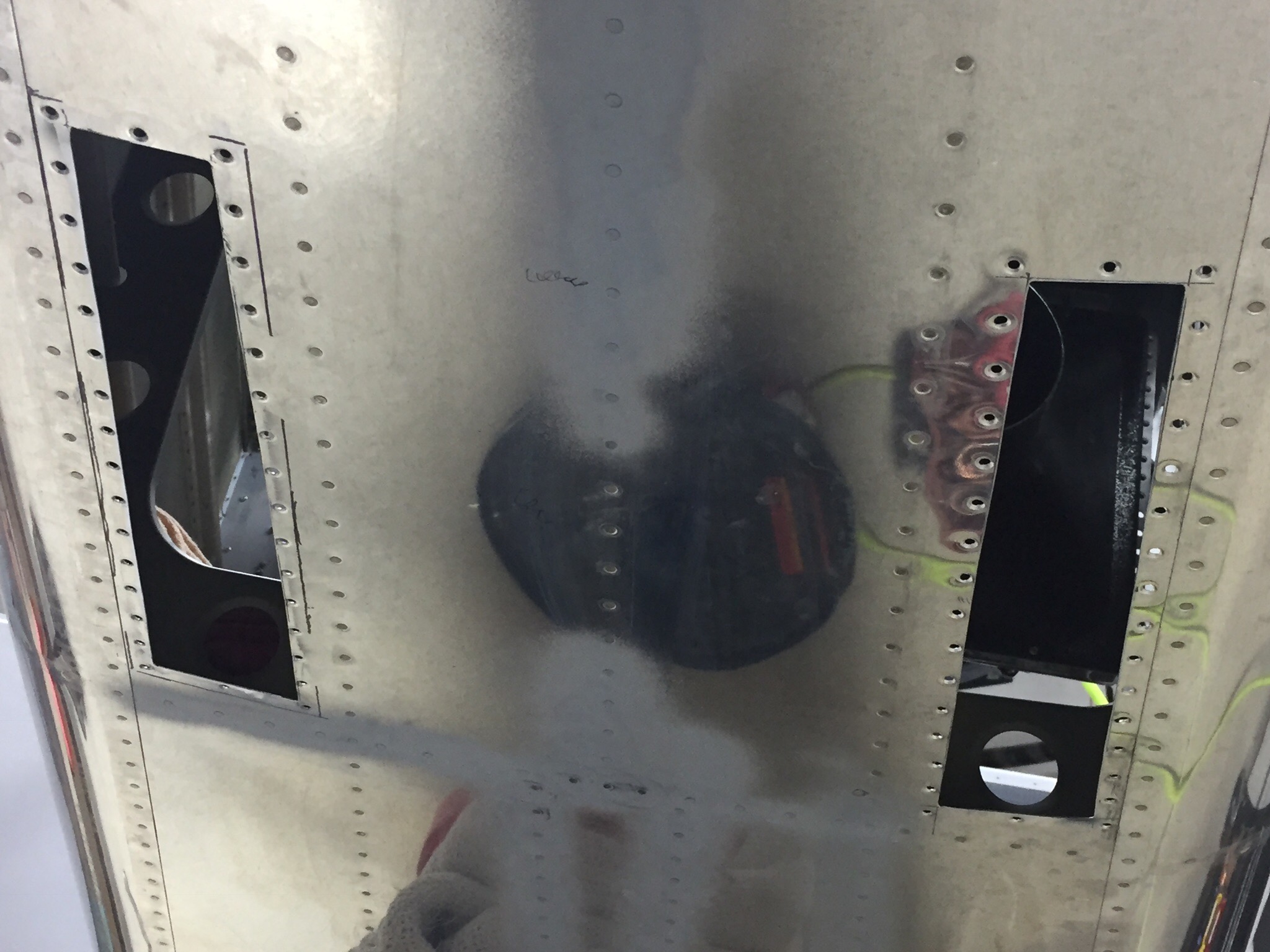
The next task was to mount the intake and exhaust vents for the condenser. While at Oshkosh, I spoke with John at Flightline (owned by Kelly Aerospace now) about an alternate side mounted intake. There have been some builders concerned about CO infiltrating the cabin with the original belly mounted vents which are in the exhaust stream. I agreed to design a new side mount intake similar to Cirrus retrofit kits. While I am in the process of laying up said vent, I ultimately decided that I was comfortable with the stock setup and ended up going that route.

I created a paper template of the vents after cleaning the old silicone caulking from them and cleaning up the rivet holes (this was a used kit pulled from a flying RV-10). I used the template to mark the holes and cut lines on the bottom of the tail cone. I measured fifteen times and cut once with success!

I used black RTV to create a good seal around the vents which will prevent air from leaking into the cabin area. Once riveted in, I was really happy with the results and finished up by connecting the 6″ duct work to the plenum and securing the clamps. I also added a new drain line from the evaporator which runs down into the exhaust vent and secured it using more RTV.

I’m really excited to have this done and happy with how it turned out. I chose this kit vs the Airflow system because of it’s low profile install and electronic controller which is really slick. Users have reported good performance and this will make our adventures even more pleasant by keeping the cabin comfortable in the southern summers.