I just need a little air

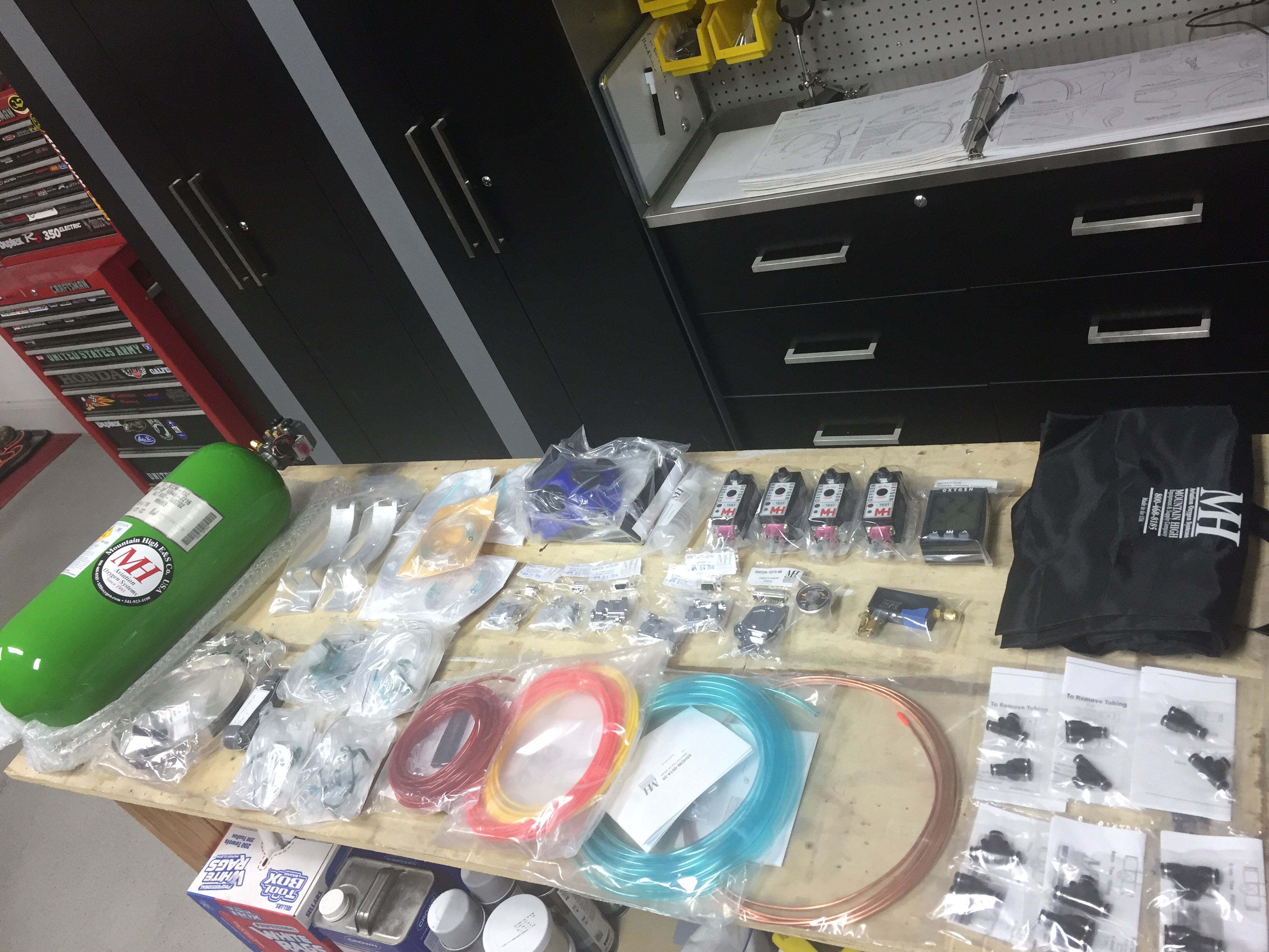
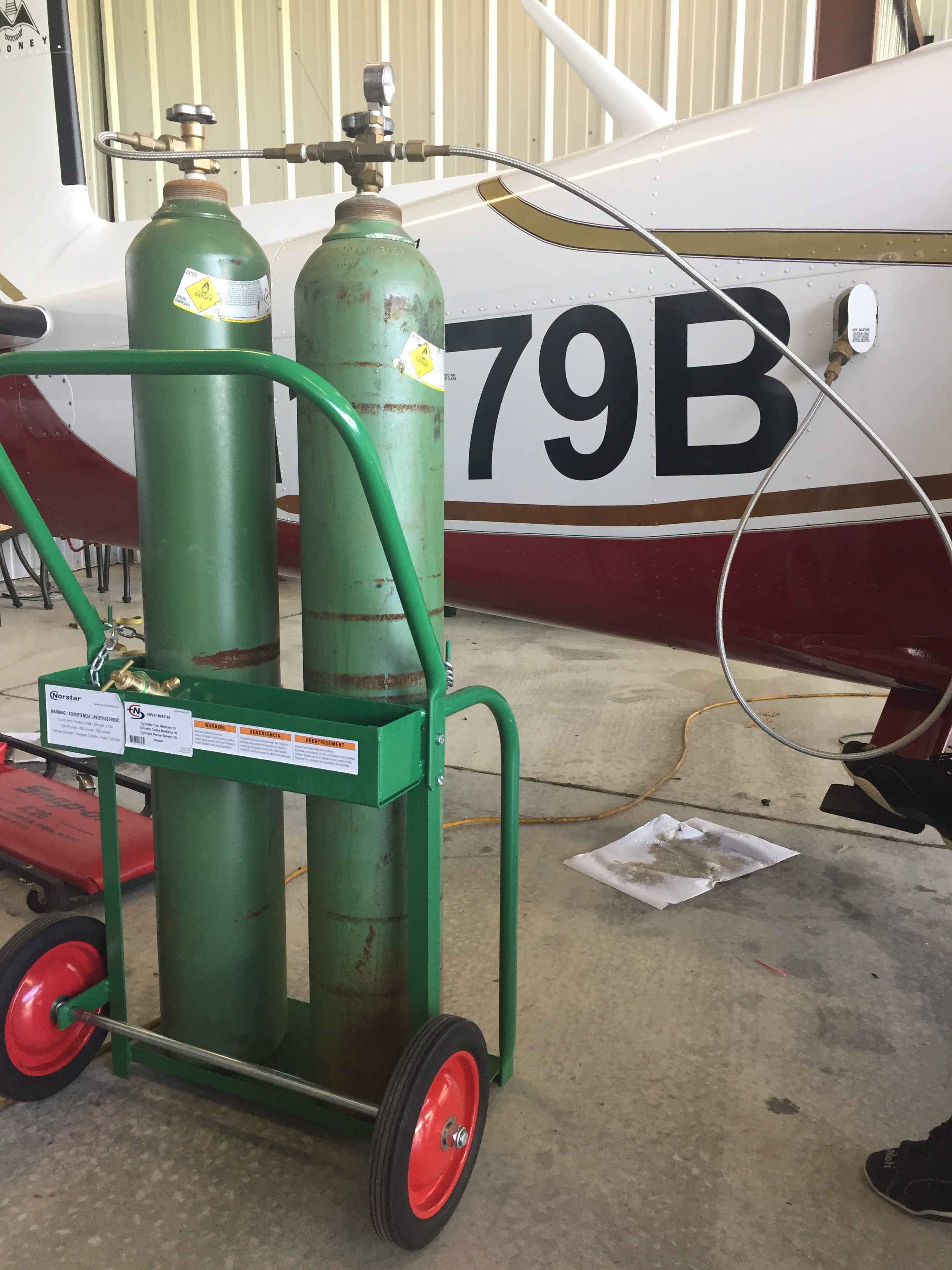
We have big travel plans for this airplane and a great way to take advantage of weather on a long cross country flight is to climb up high. In order to do that, you need supplemental oxygen. There are many ways to do this but I wanted to go with the top of the line, integrated solution from Mountain High.

The 4ip setup is all electronic control, pulse demand system which allows greater conservation of oxygen while giving better flows to the people on board. I was able to score a significant discount via Oshkosh this year and it’s a great time to install the system before the interior goes in.

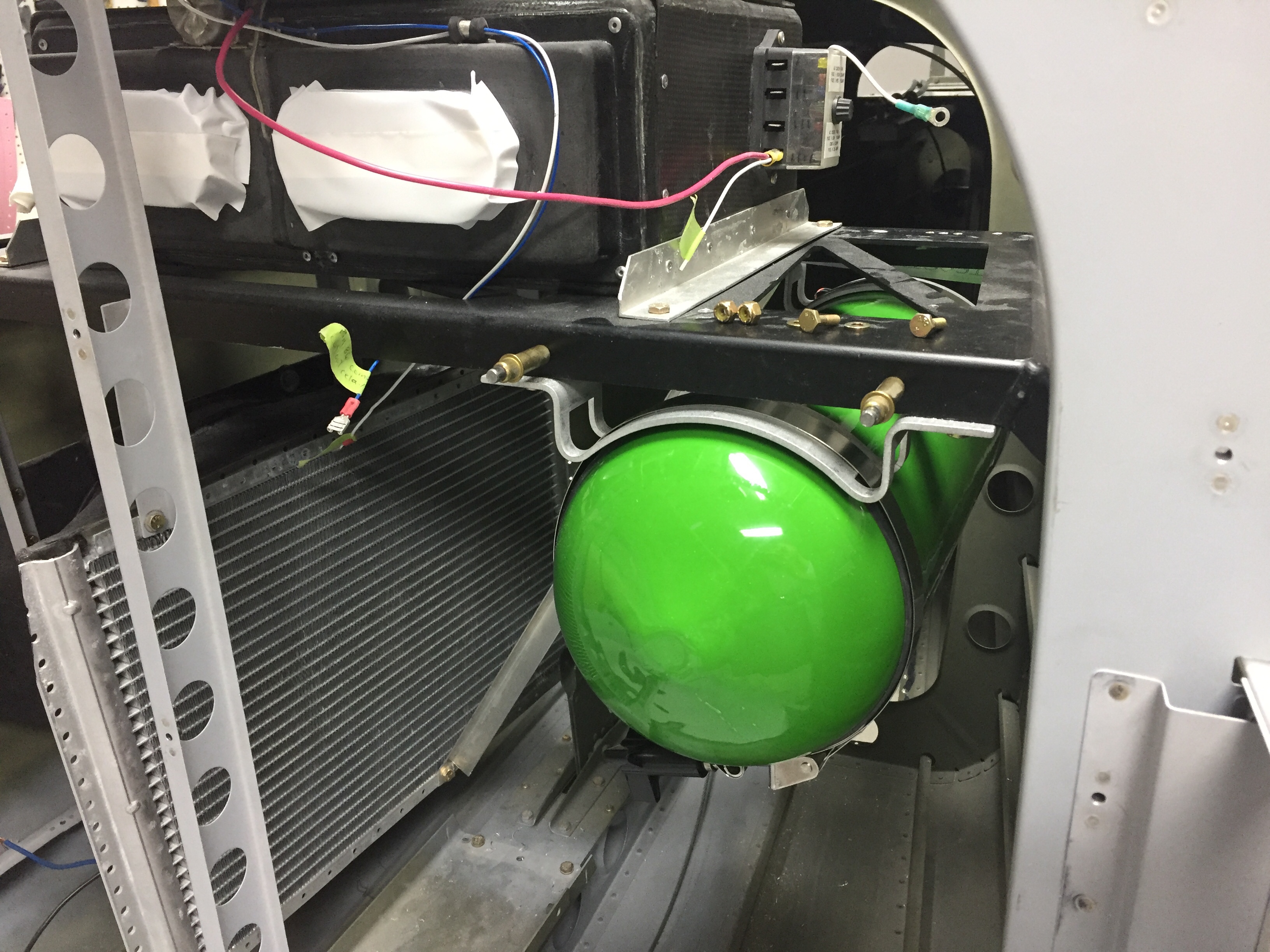
All laid out, it’s pretty intimidating, but as with everything it’s eaten one bite at a time. The bottle and regulator are the main component that needs to get installed behind the baggage bulkhead. Some folks have mounted it on a tray but I chose to take advantage of the air conditioner equipment tray and hung it from angle aluminum.

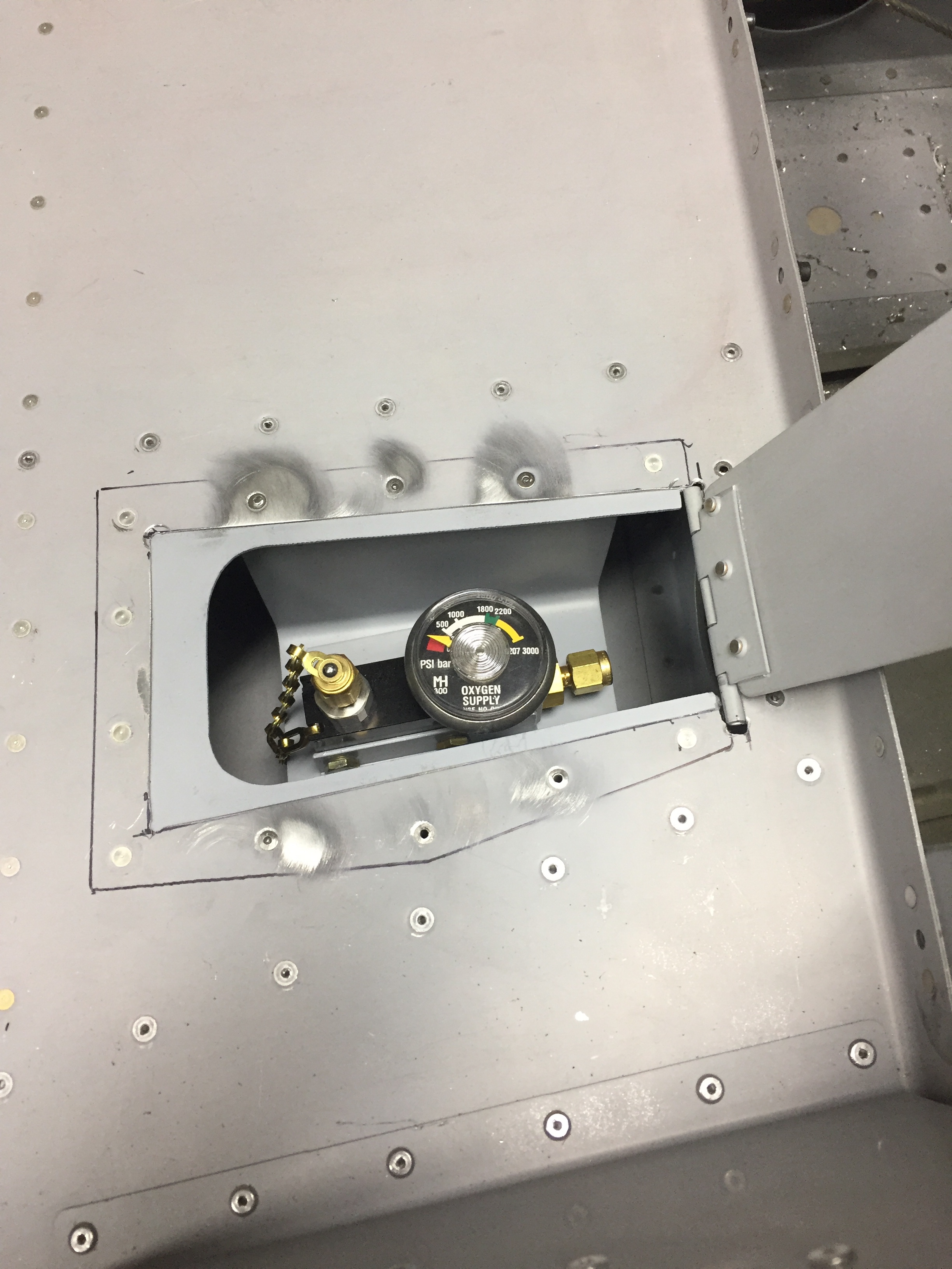
Then it was a simple matter of running some wire making the connections to the bottle. I also installed the remote filling valve in a panel underneath the baggage floor. Gaylon did this in his and I really liked the idea which is why I copied it. I’ll add a little cutout to get a better handle on the cover but it will all be covered by carpet so no need for a latch or anything. A flying buddy and I have already partnered on a cascading setup to refill the tanks on our own with him having a Mooney.

The tubing will run up the center console and go to the panels for the front seats and console for the rear. Once my center console comes in, I’ll install the user side of the system. The control head will be mounted on the lower center instrument panel up front.

Kool like Krantz

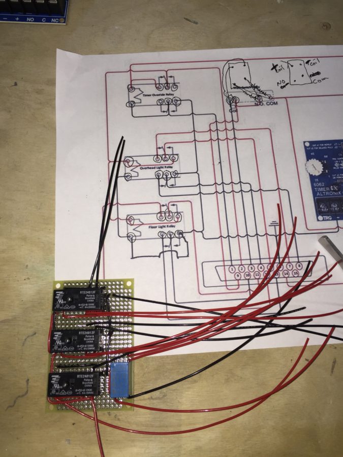
In between working on the overhead console, I decided to tackle a fun little project dreamed up by Ed Krantz (Good Plane Living) to control the interior lighting. He came up with a fancy little box full of relays and a timer to essentially make the lights behave as a modern car. While this doesn’t seem fancy, most little airplanes have one dome light from the 1960’s, so this is all pretty high tech. The best part is he designed it to work as a DIY project and kept it simple and functional. The best, best part though is he shared it online for others to benefit from, so thank you!

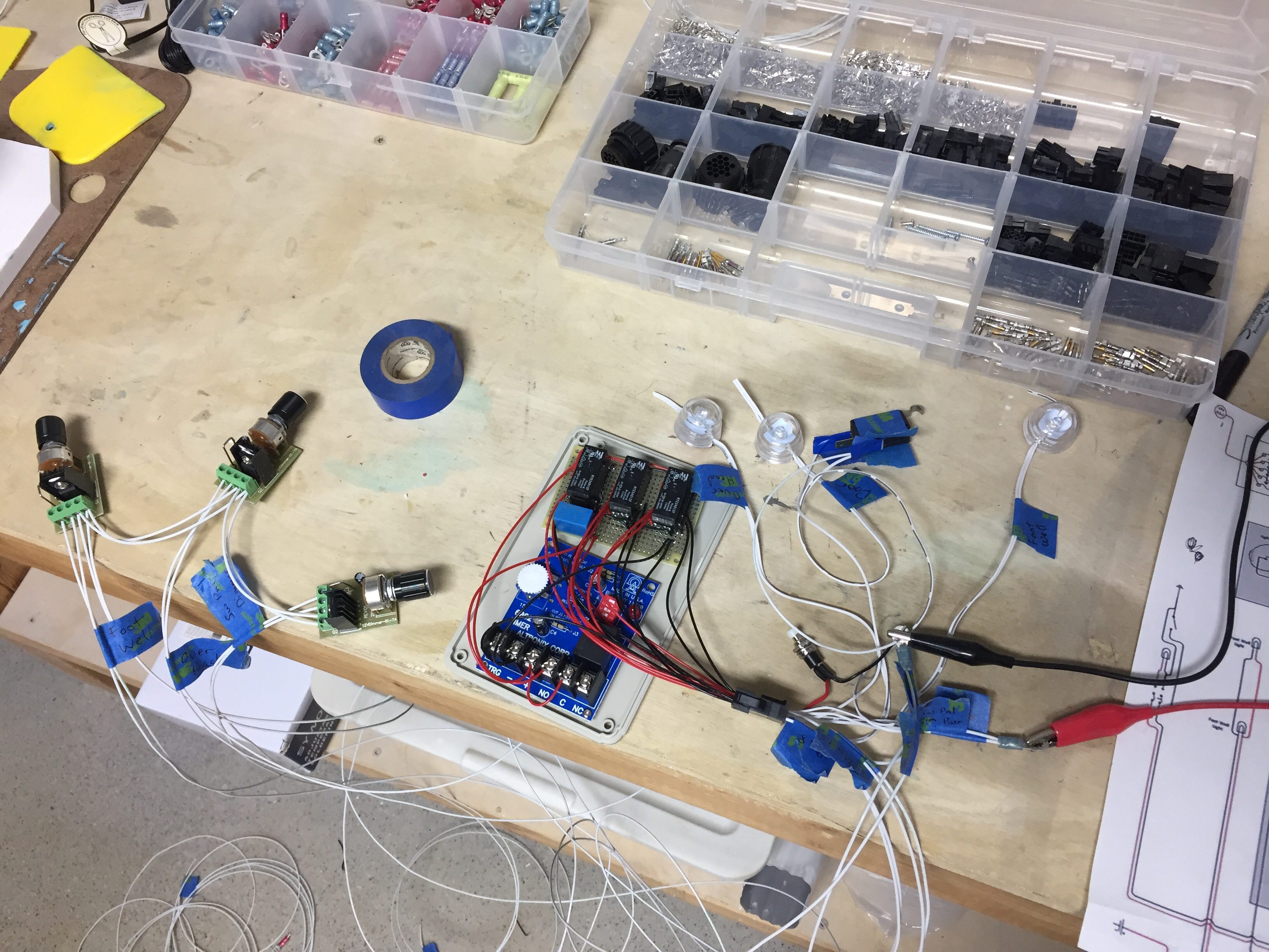
Without diving into the actual wiring schematic, the little box receives a signal from a micro switch that a door has opened. This in turn causes the three overhead LED lights to illuminate, the footwell lights, and under panel lights all to come on to full brightness, even if they were on using the dimmer. The timer is used to keep them on for a set amount of time then they all turn off. Once the door is shut, the whole system resets and the lights return to their prior state, either off or according to their dimmer.

I’ll have two additional LED lights, one on each door, that shine down on the wing when the doors are open. Ed had put each task light on the control as well, but I chose not to since I think the three overhead will provide plenty of light.

It also has a manual reset switch to allow a door to be open but reset the lights to off or dimmed in case you want to have a door open while taxing or any other reason. There will also be a master switch near the rear baggage door to control overall power. This is because even after the lights are reset, the timer does draw a small amount of power and in theory could drain a battery if left for many days, for example during extended maintenance.

After a few hours of laying out the components and soldering it all up, I hooked up a few cheap-o LED lights to test it all out. Just as Ed did, I forgot one ground wire but that was soon fixed and everything worked just as designed. It was a really fun project and will make night flying / loading a non-issue.

So on the overhead control panel, I will have all lighting switches (Nav, Strobes, Taxi, Land, Interior Reset) along with the dimmers for the panel, instruments, and interior lights.

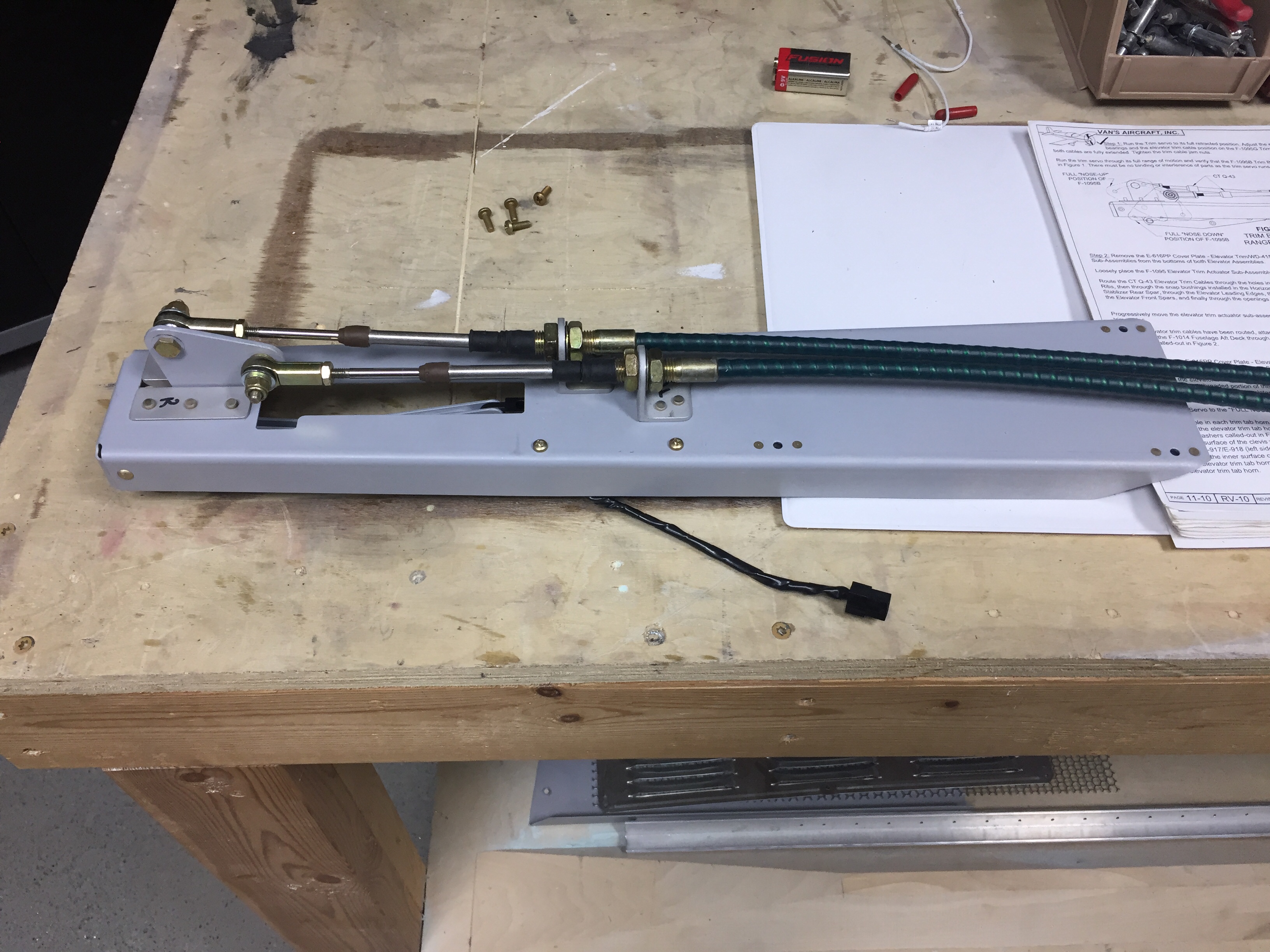
I also fabed up and installed the pitch trim servo mount. It was a pretty quick job and the wiring for the servo was already pulled during an earlier build session. I’m trying to get as much wiring roughed in now before much more structure goes in place.

Meanwhile, overhead

While the air con project was underway, my time was split between it and the cabin cover. After rough fitting the overhead and wiring it for the lights, I had to start the cosmetic work. My first task was to contour the forward door / windshield supports. Others have left these and just cleaned them up while some have filled it in to make it look just a bit cleaner. A few folks will run conduit in the jog and then fill over it to route wiring to the overhead. I chose the middle option, just wanting to fill them in for a fuller, more finished look. My wiring will be going through the center post so no need for conduit.

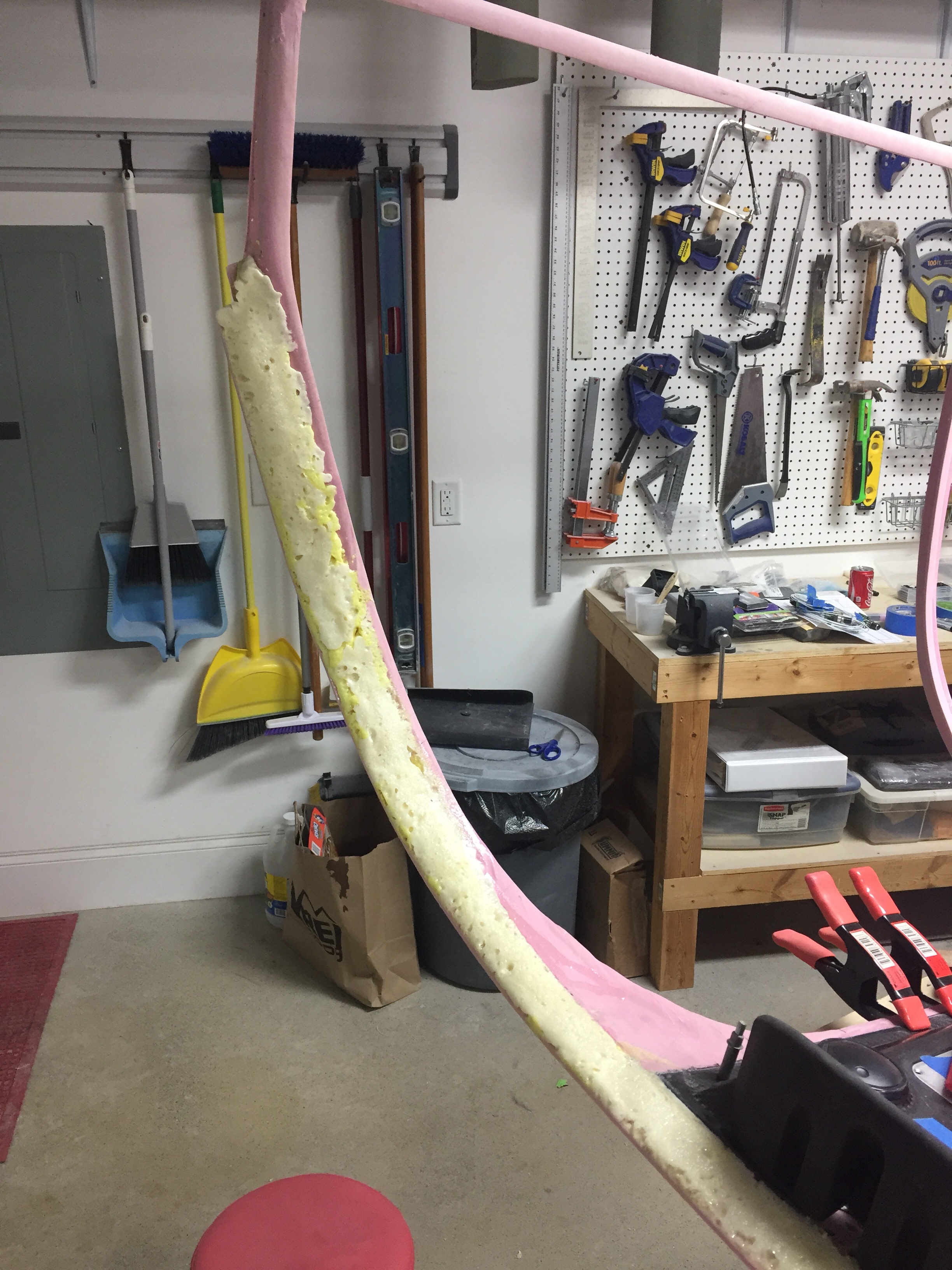
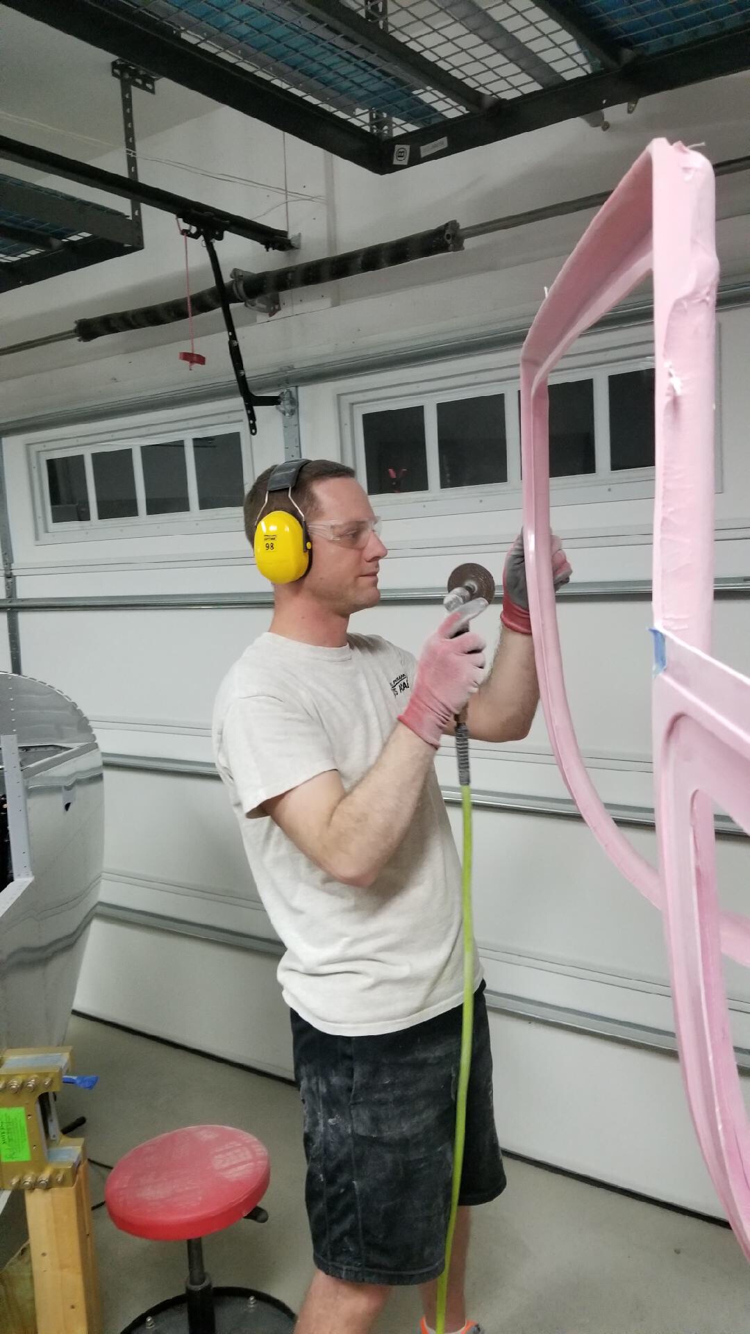
I used the closed cell spray foam insulation and piled the stuff on. It’s a messy job and I had to use quite a bit since it’s not exactly sticky and wanted to run off on the more vertical surfaces. After it cured for a day, I used a flexible saw blade to do a rough cut. There were a few low spots and a lot of holes that needed filler. I also floxed on the overhead console after a good pause to make sure I’m not getting ahead of myself. It was a straight forward process and is super solid now.

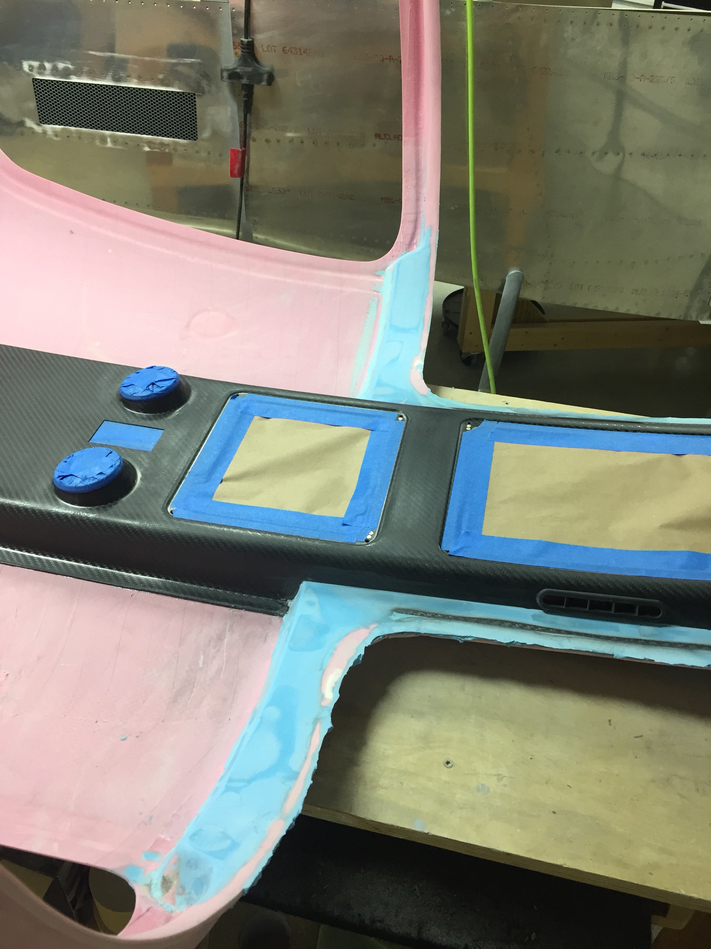
Now that the overhead is in, it’s time to start making it all look good. Out comes the Super Fill and the mixing board. I really like this stuff, it’s easy to measure (2:1) and easy to mix up. Best of all, it’s simple and easy to apply and pretty forgiving. The sanding is trouble free as well and it’s very light. Really, it’s just the best and I regret not using it before on the fiberglass tips, etc.

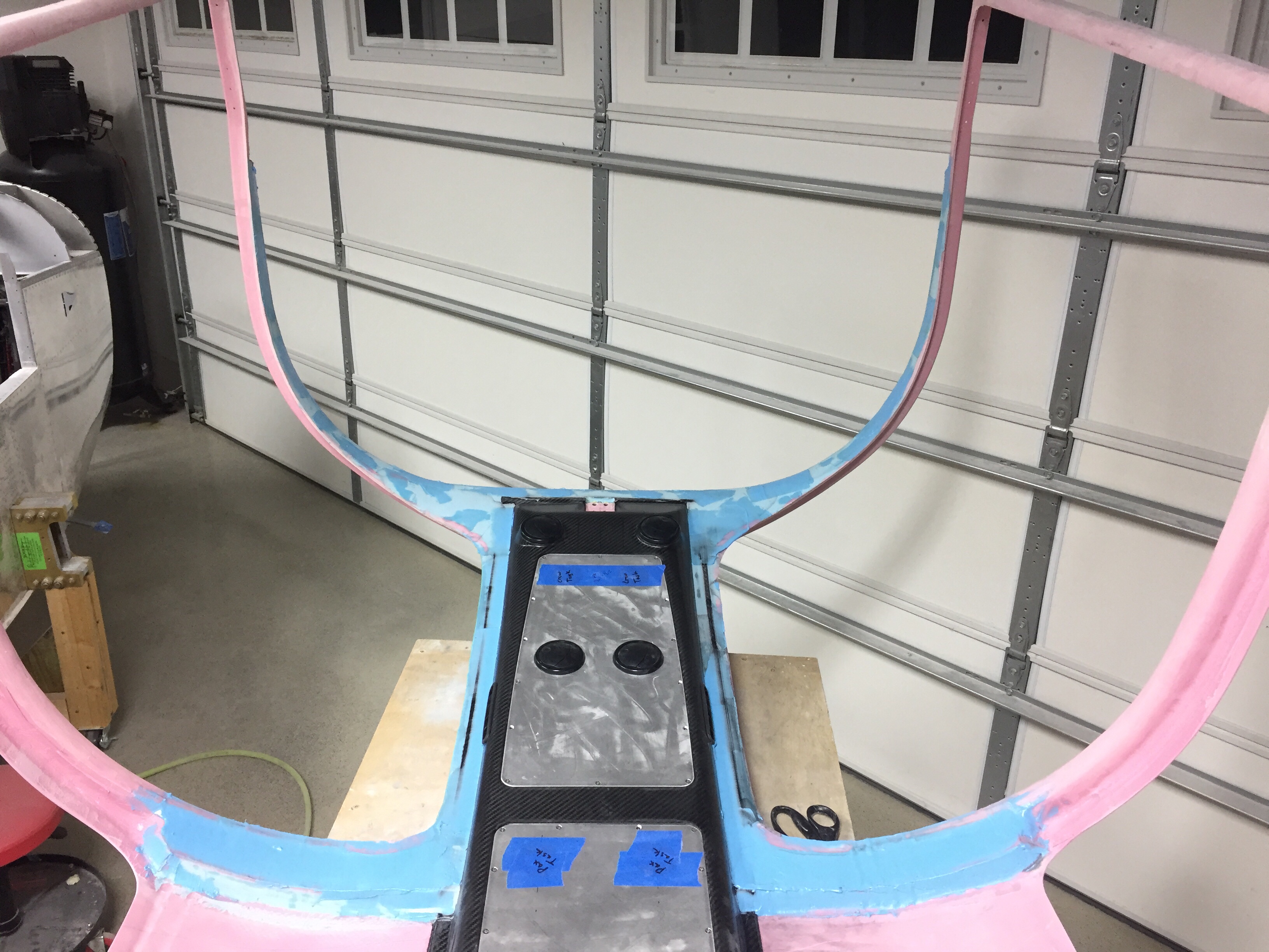
I mixed and applied for a good hour the first night and got the overall shape done along with filling in the overhead. I’m not worried about the areas covered by the headliner so that saves a lot of surface area that I can essentially ignore. I cleaned up the aft door supports as those will stay as is. I also installed the switch console and filleted the seam between it and the overhead. This seam won’t be perfect but it just makes it look a little cleaner, albeit not one solid piece.

And so it went for four or five evenings. I start by using my sanding blocks to clean up the now cured filler. After it’s all smoothed out and I can tell where additional filler is needed, I mix it up and apply. Then I moved onto the A/C or whatever other project of the evening is. It really hasn’t been a bad project and it’s rewarding seeing it take shape.

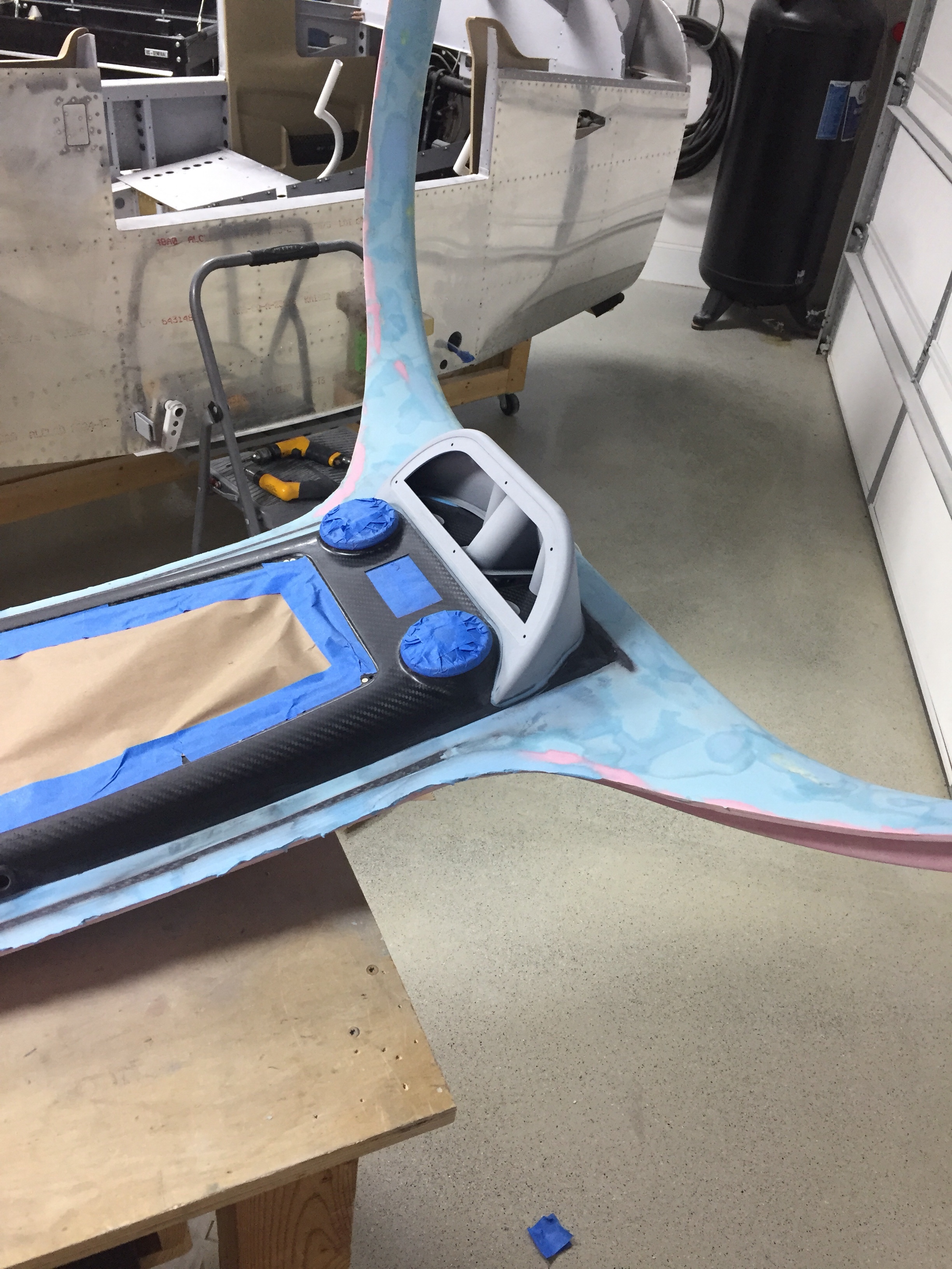
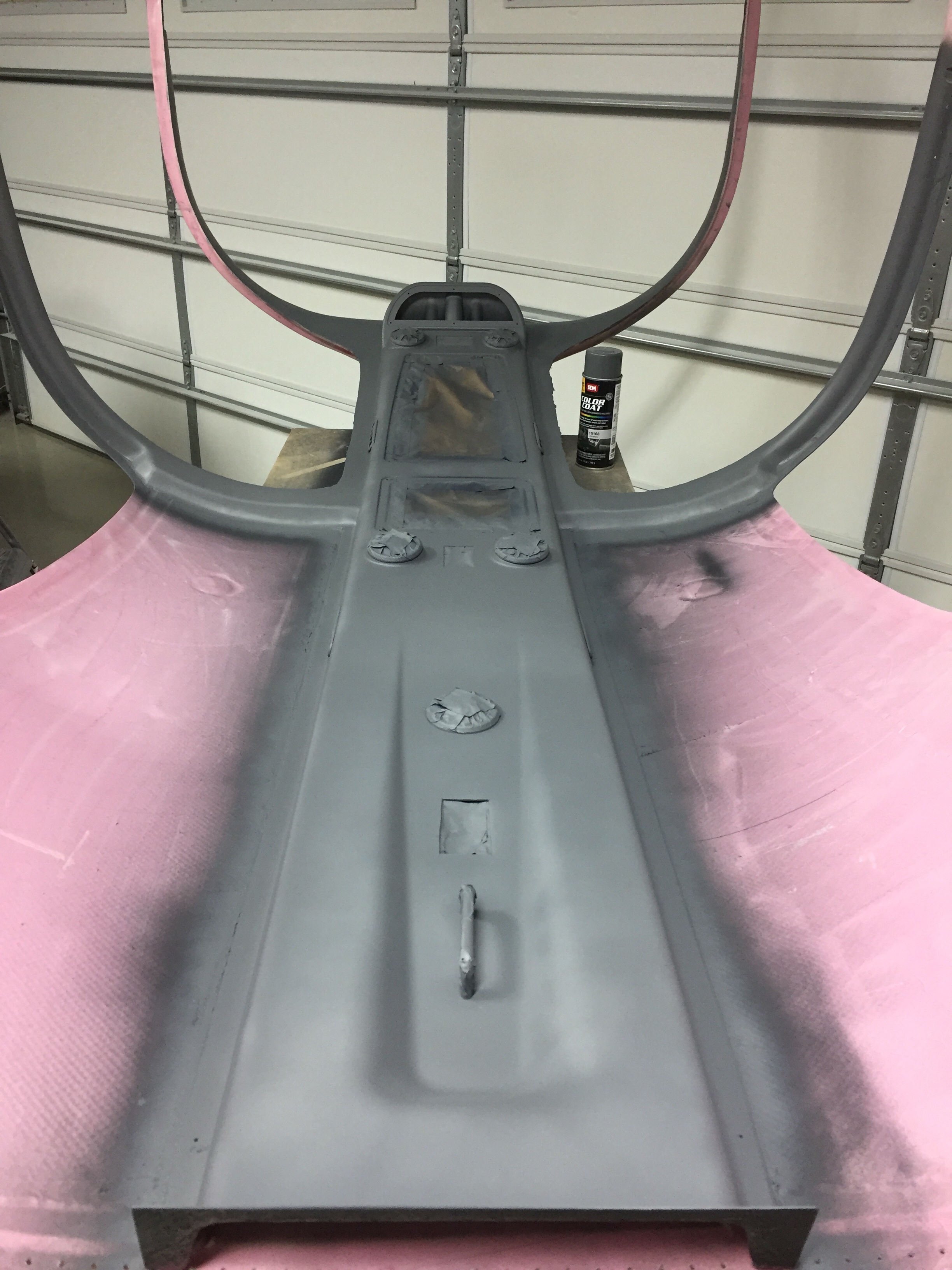
Finally, it was about as good as it is going to get, so I used the SEM high build primer to highlight any pins holes still hanging around. I few touch ups with some glazing compound made it all ready for the first coat of paint.

I sprayed a few coats allowing each one to flash and as always, the Color Coat provided good coverage. I am somewhat concerned that I’ll have some adhesion issues, as a few spots that will be covered by the headliner chipped pretty easily. The carbon has a very hard epoxy and even though I scuffed it, I’m not sure I did it enough. I should have also used an adhesion promoter looking back. I’ll use that for the rest of the carbon and the panels. Overall, I’m pretty happy with how it turned out and while it is not perfect, it is more than good enough for me.

Full of hot air

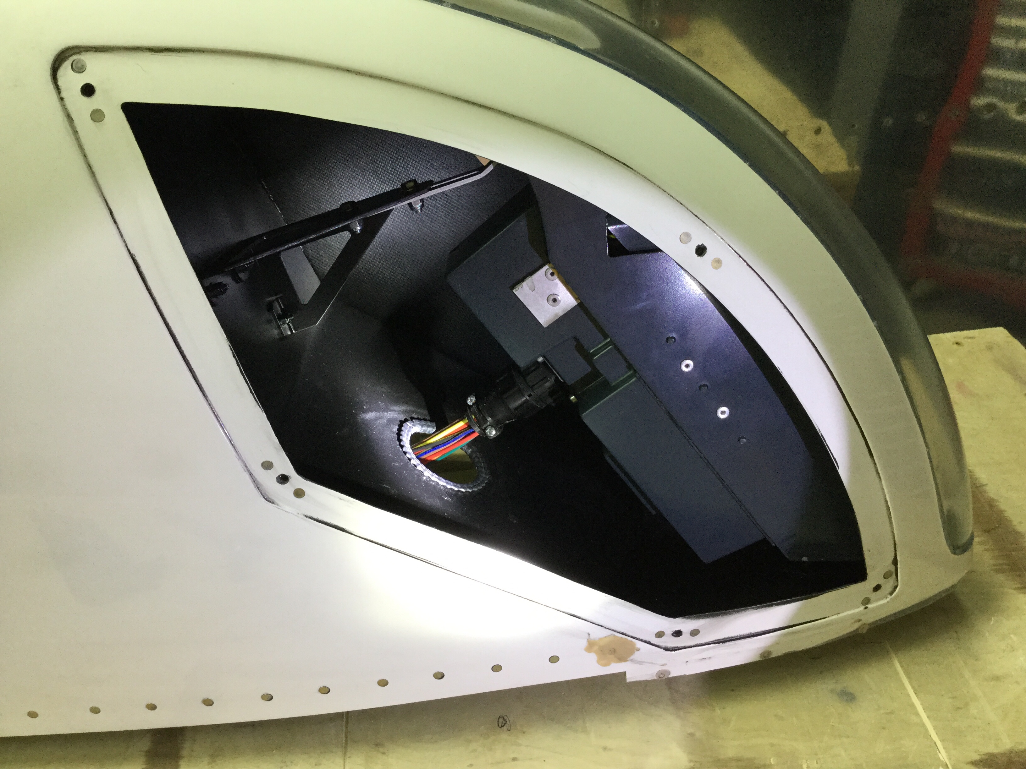
Anytime you have to cut a huge hole in the side of an airplane, your palms should start sweating. Mine sure did, especially since I’ve already cut two holes in the bottom of my airplane. Since the condenser duct system was cured and ready for install, I marked the exhaust cutout area got the Dremel out.
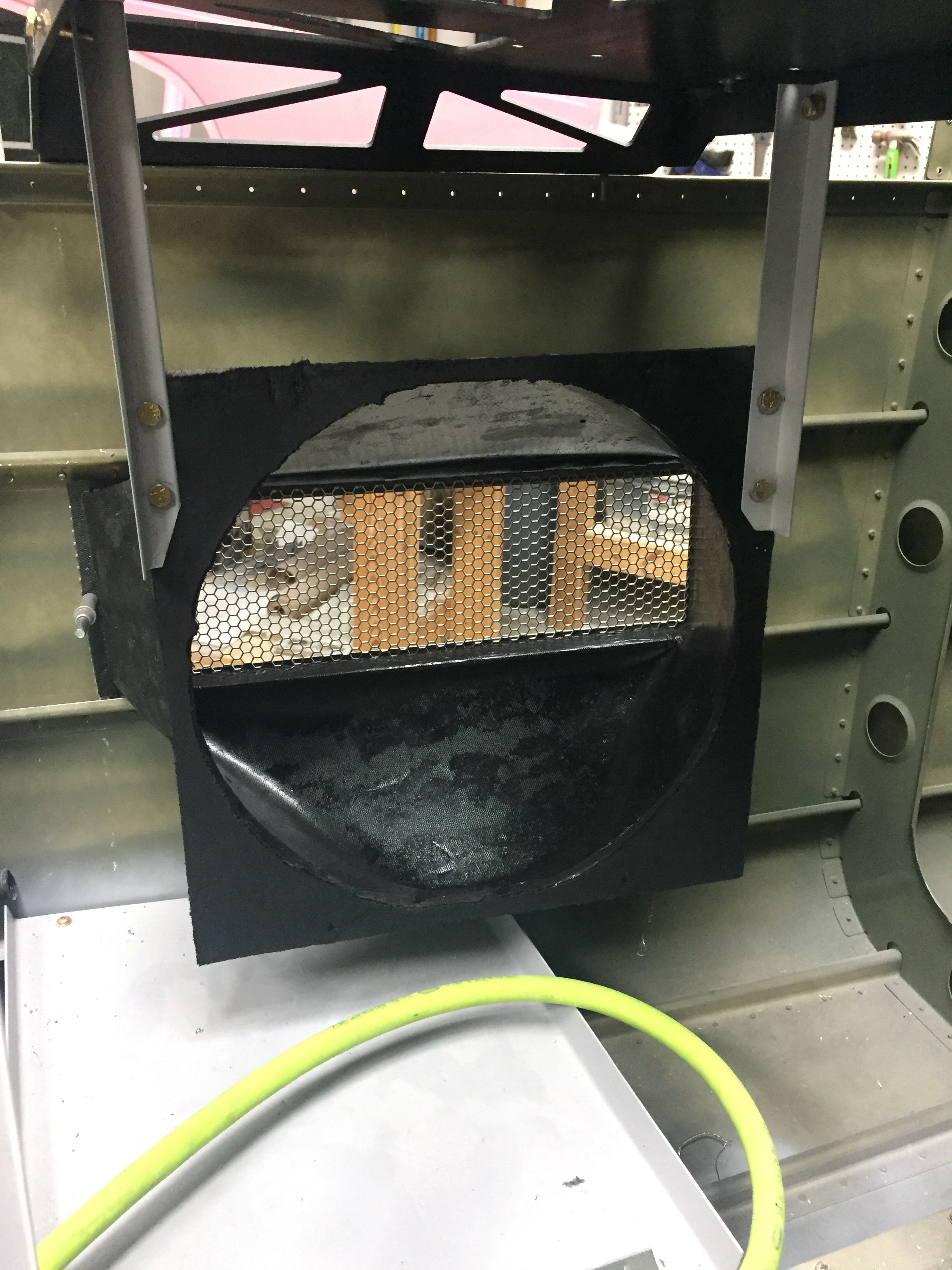
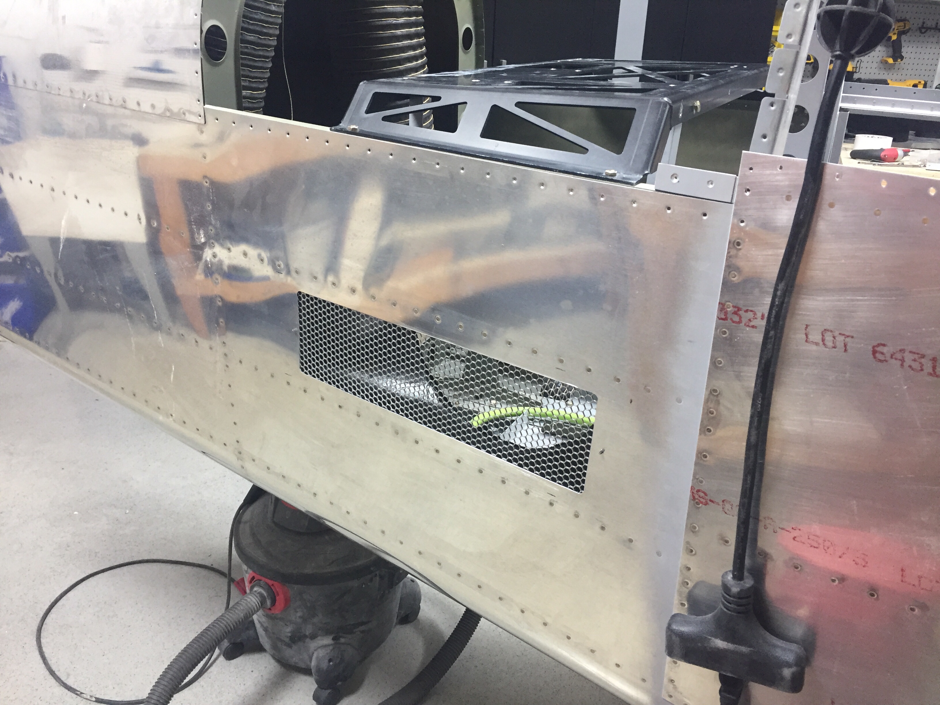
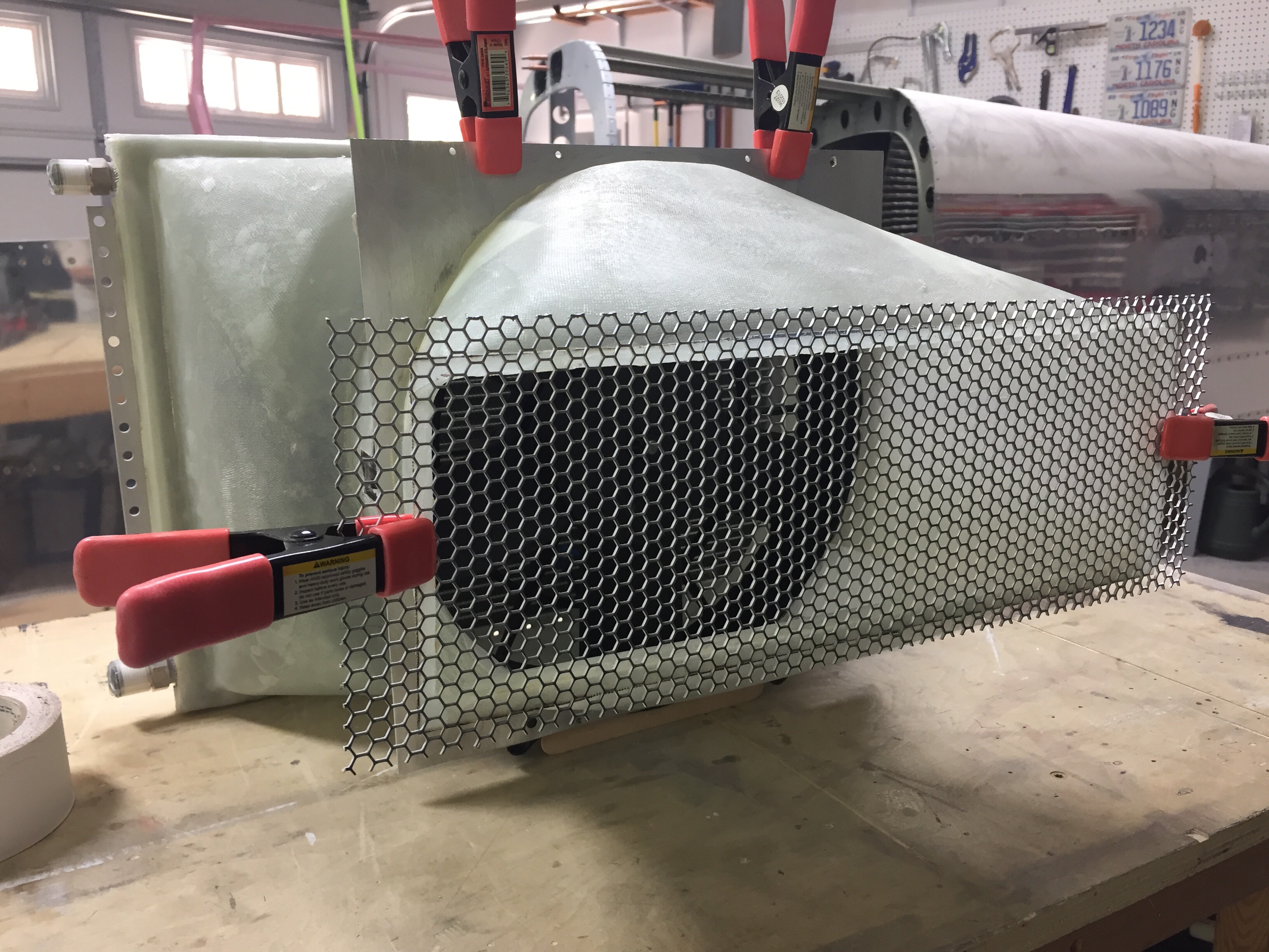
I had already ordered some auto grille material that provides some debris protection while allowing good air flow from the fan. It’s very similar to what Beechcraft is using on the Bonanza. I spray painted the plenums to minimize cosmetic issues once the plane is all finished. I used flox to epoxy the grille and duct onto the skin, making sure the grille didn’t have any extra epoxy on it. Once that was all sorted, I got the fan mounting plate hung via angle pieces to the AC equipment tray. The fan bolts to the mounting plate which is sealed to the plenum with a gasket made of neoprene, so the fan is replaceable and will also allow me to block off the fan during final paint.
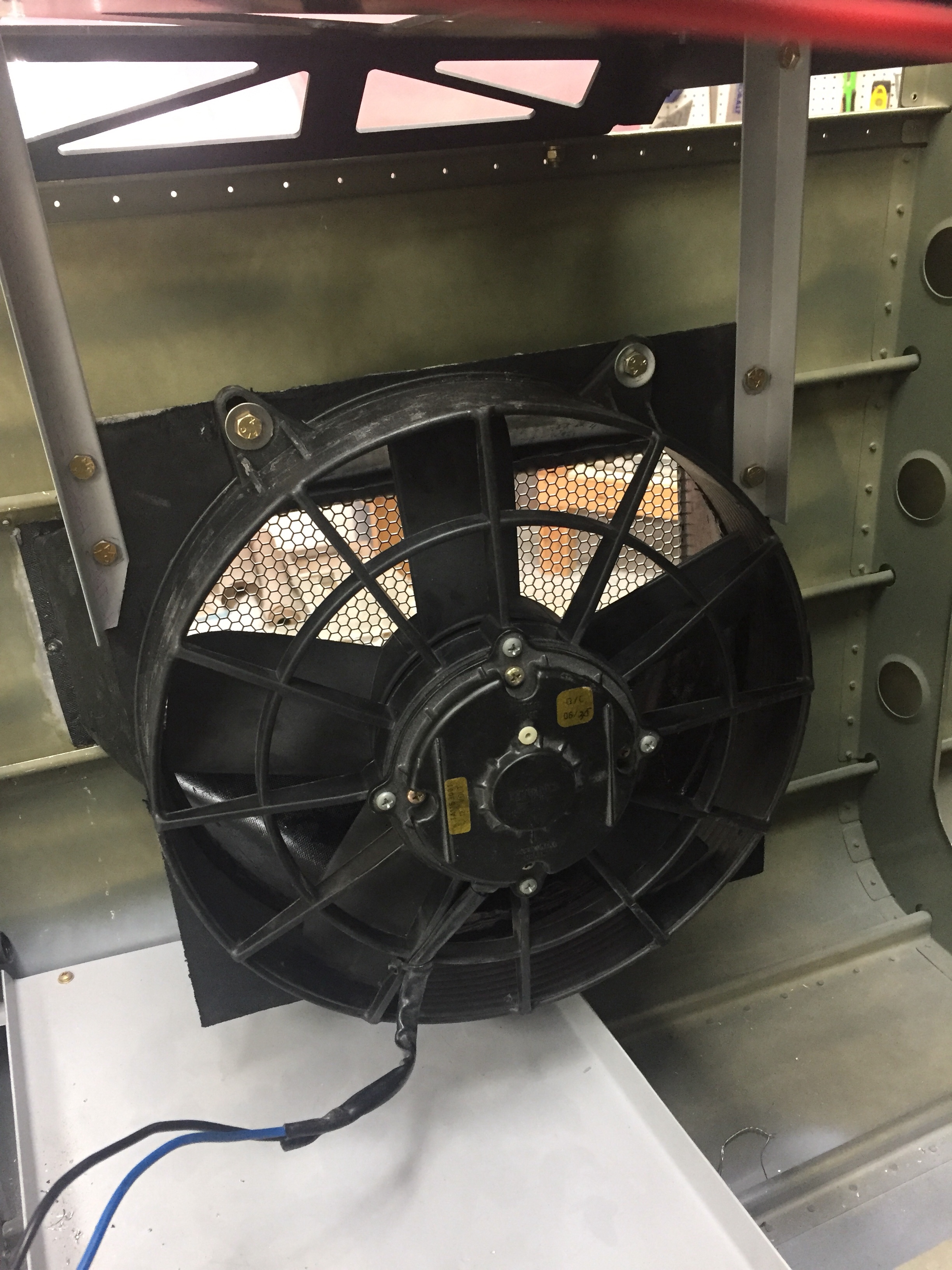
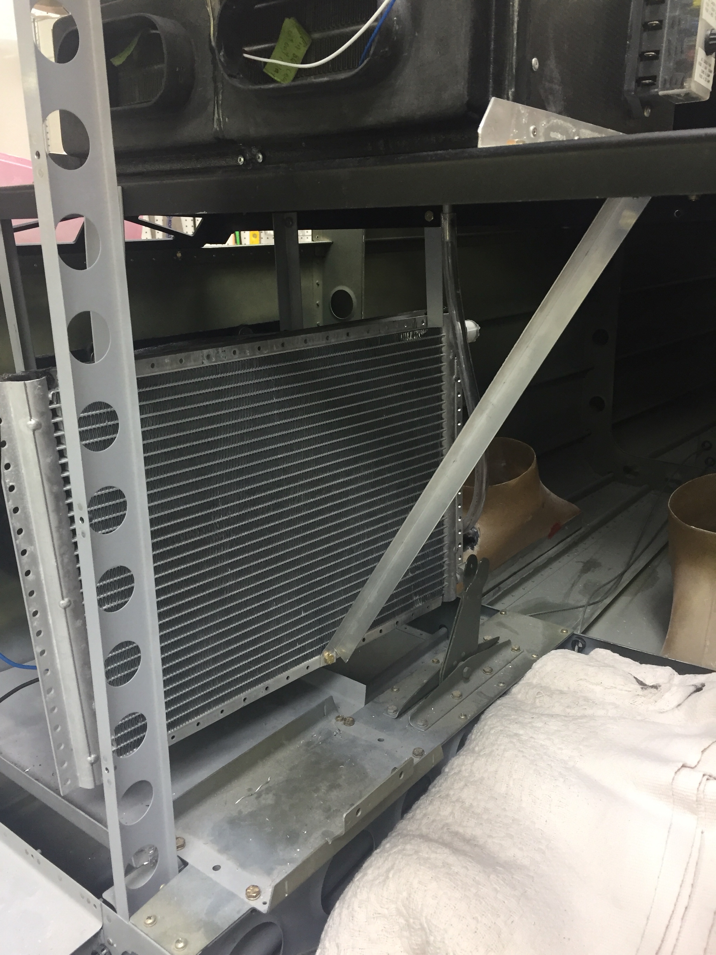
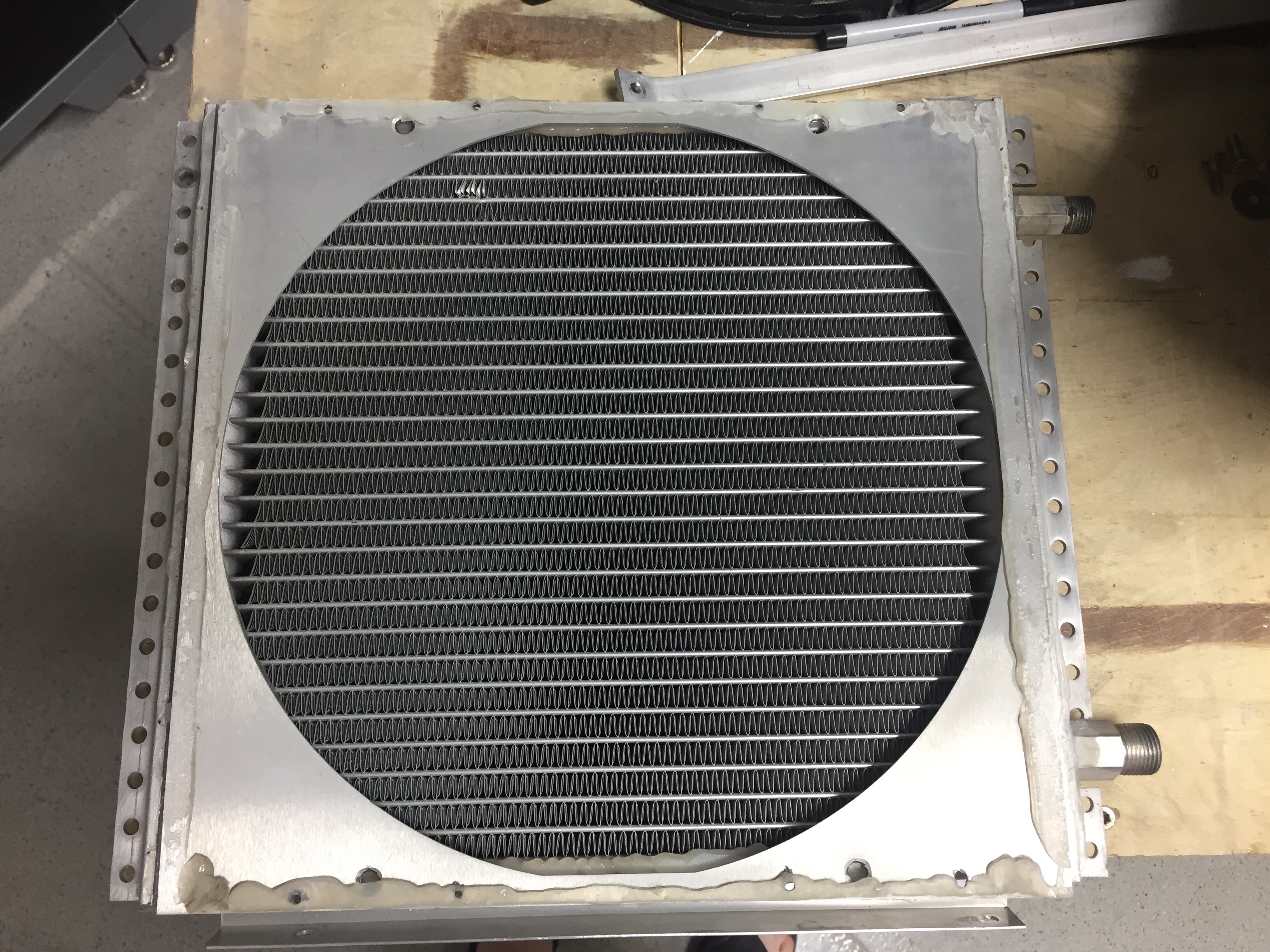
Next is the condenser to fan plenum which I sealed to the condenser with silicone. This slides over the fan frame and is sealed with a small bead of silicone around the seam, keeping the air moving where it should. The condenser also hangs from the equipment tray and has a flat stock support bar that keeps it from swinging. Once it was all together, it was very stable and will still allow a very tight, but passable cavity for me to crawl into the tail cone.
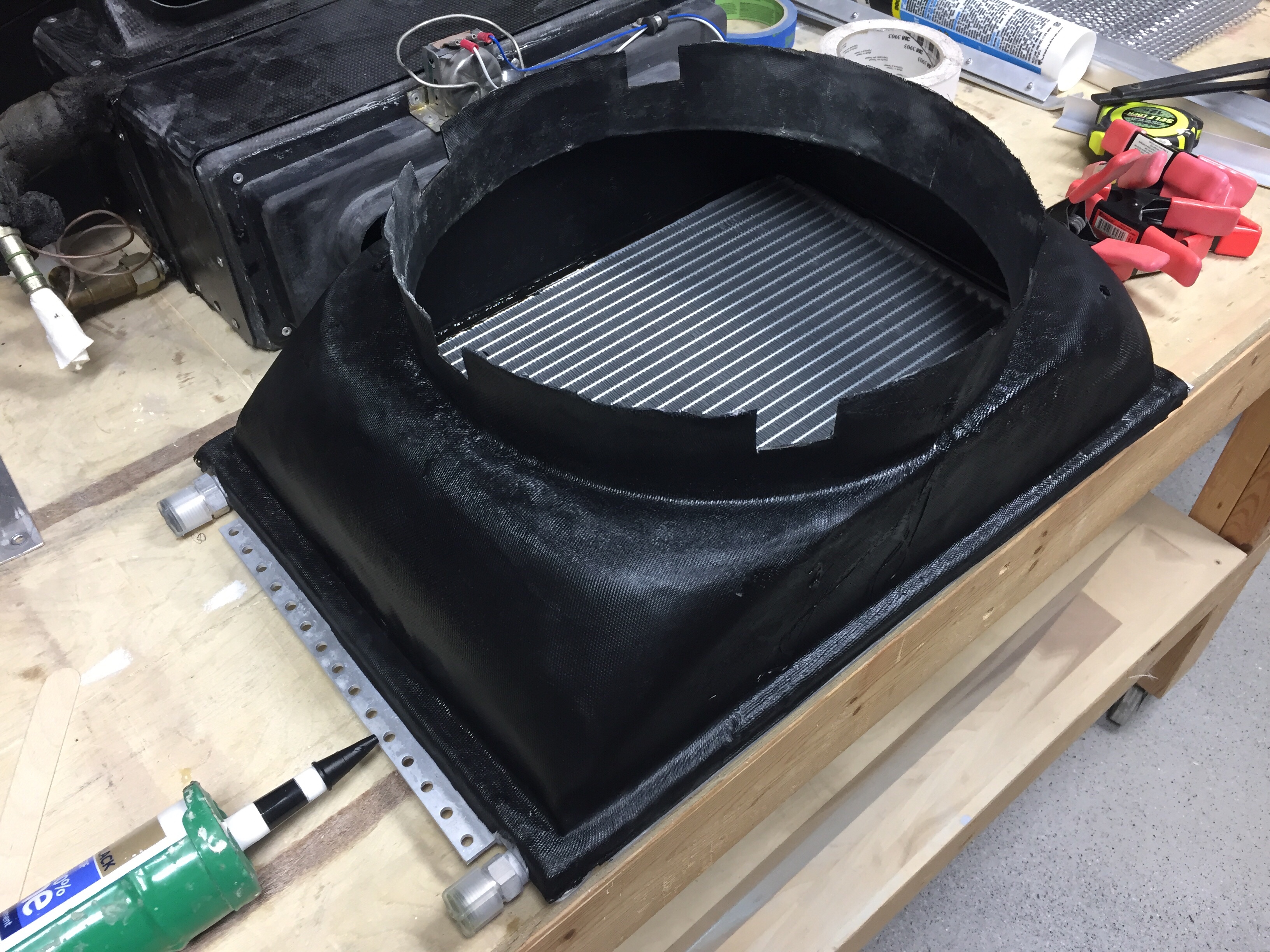
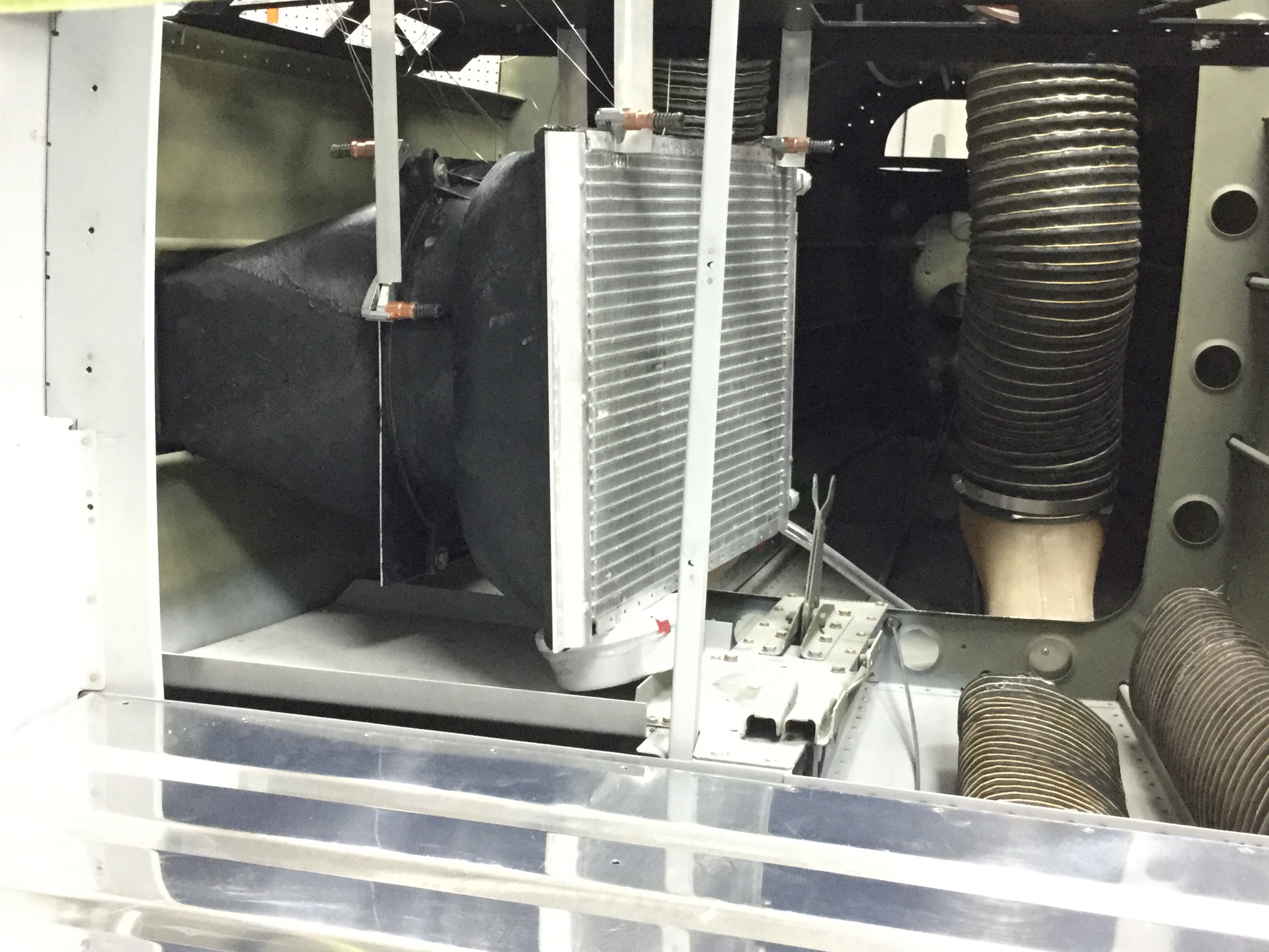
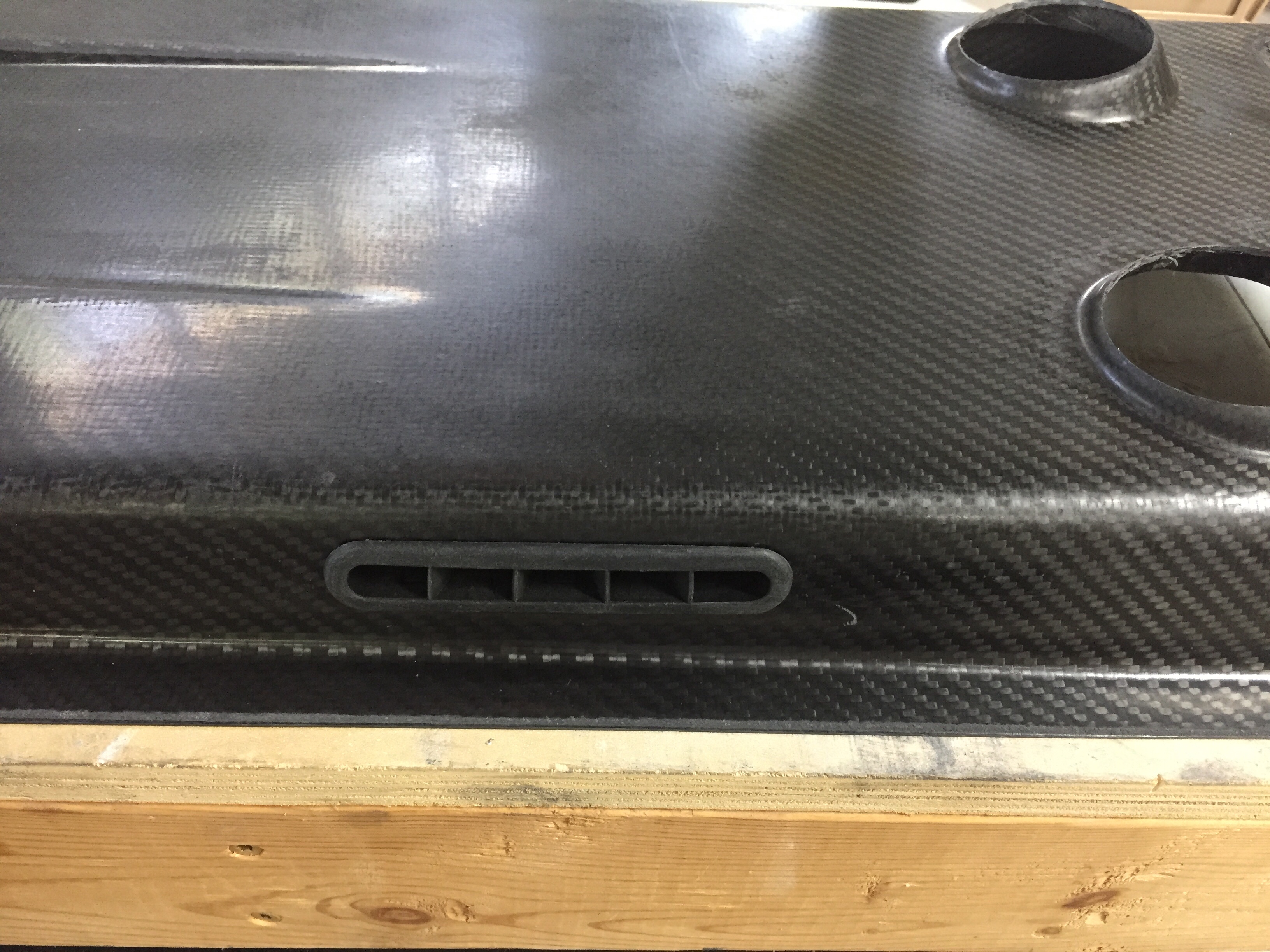
The clearance between the condenser and the pitch torque tube and pitch auto pilot servo is tight but it does all fit with no interference. With all of the equipment and exhaust ducting in place, I need to supply a fresh air source. The stock setup used one of the ducts you can see in the floor of the tail cone above, but they scooped air out of the exhaust heavy airstream. Again, like factory setups, I decided to have a vent on the opposite side of the tail cone with some small louvers just forward of the horizontal stabilizer. If any moisture does come in, it has an easy way out around the tail tie down and won’t affect electronics either.
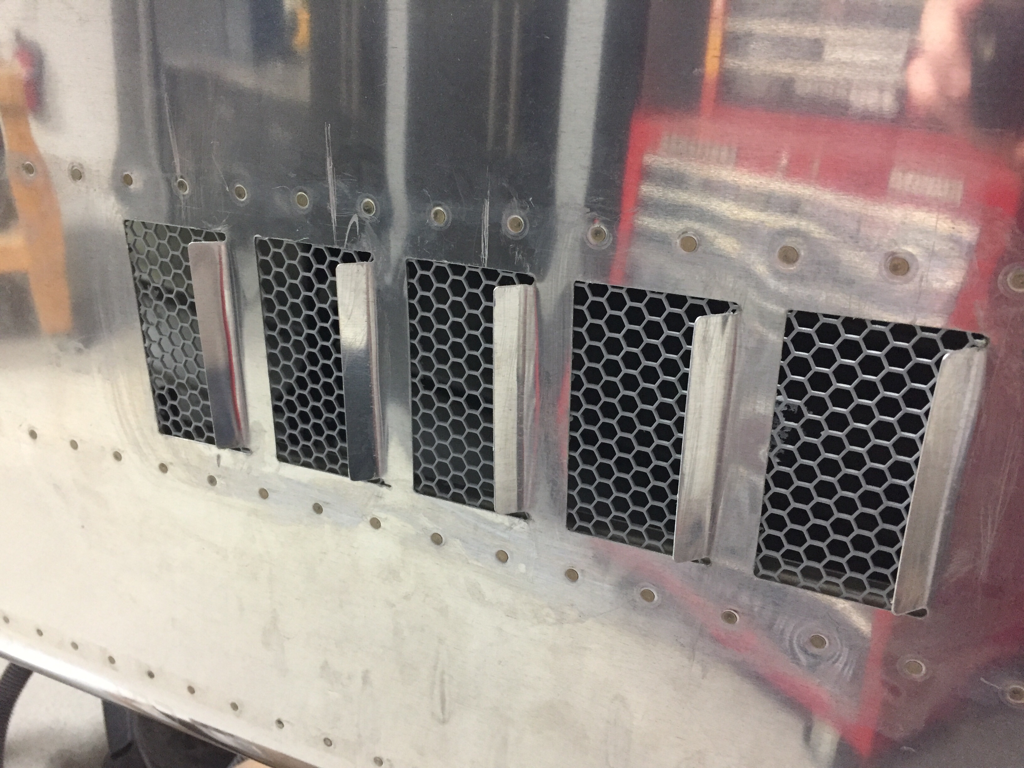
I kind of wish I had put louvers such as these on the exhaust side, but they’d be pretty easy to add later if needed, so I’ll add them after flying if I have any issues. The same grille material was epoxied in using a flow mixture that was used for the exhaust grille and plenum.

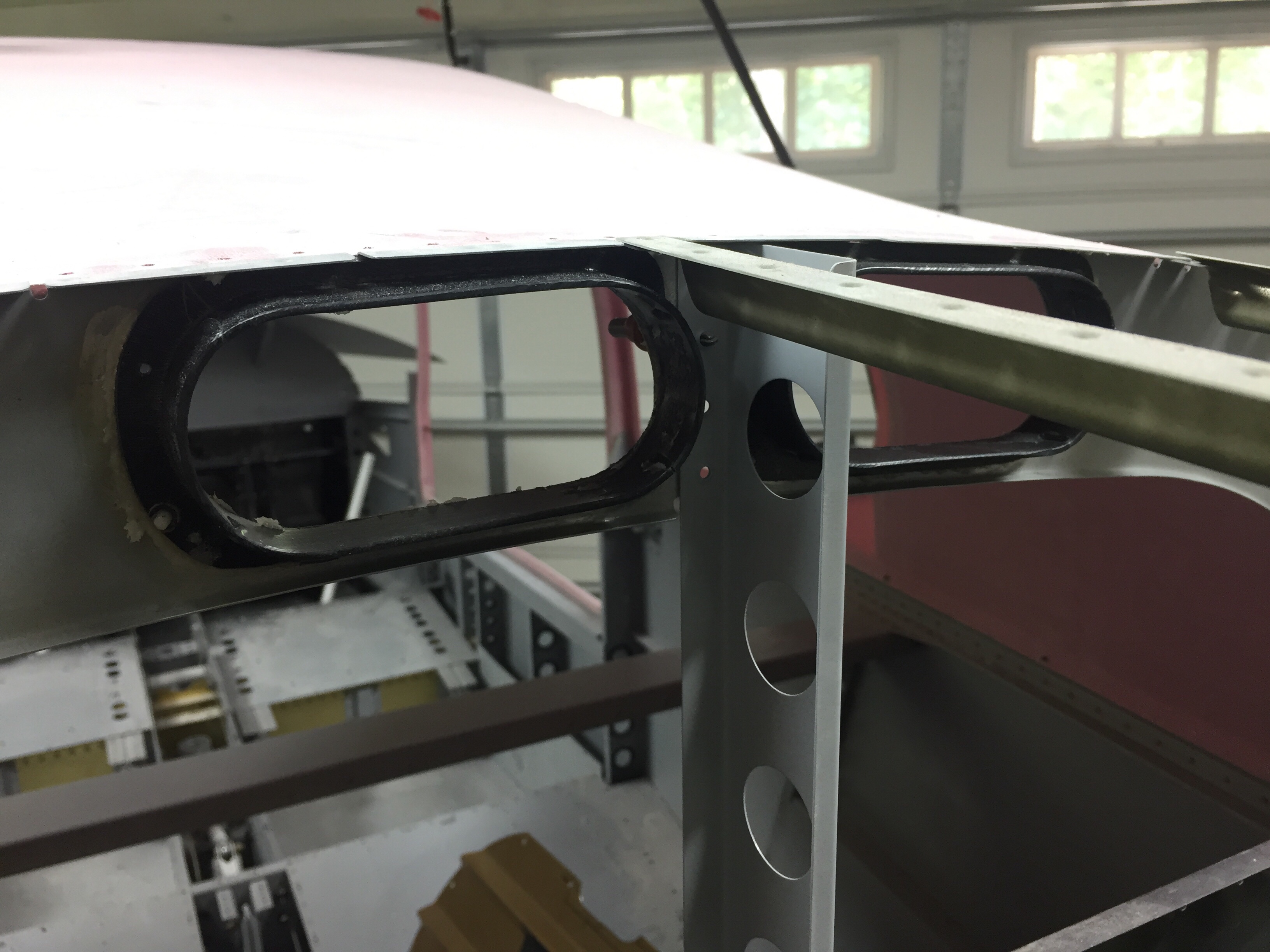
On the cabin side of the system, I cut the holes for the supply ducts into the baggage bulkhead and epoxied the duct shells into place. These line up into the Aerosport overhead console and the return air for the evaporator will go through the bulkhead itself as I am reusing the original owner’s setup and will have a faux trim covering the bulkhead to dress it up a bit.
Since I had taken everything else apart, I tore into the cabin fan box as well just to see what it looked like. It’s a pretty simple system but seems to work well. One thing I did notice was the fan speed control having four speeds. The wiring was to the low, medium, and high speeds with the max being unused. I decided to slide all three to the right so the speeds are med, high, and max which should give even more airflow out of the vents and through the cabin.
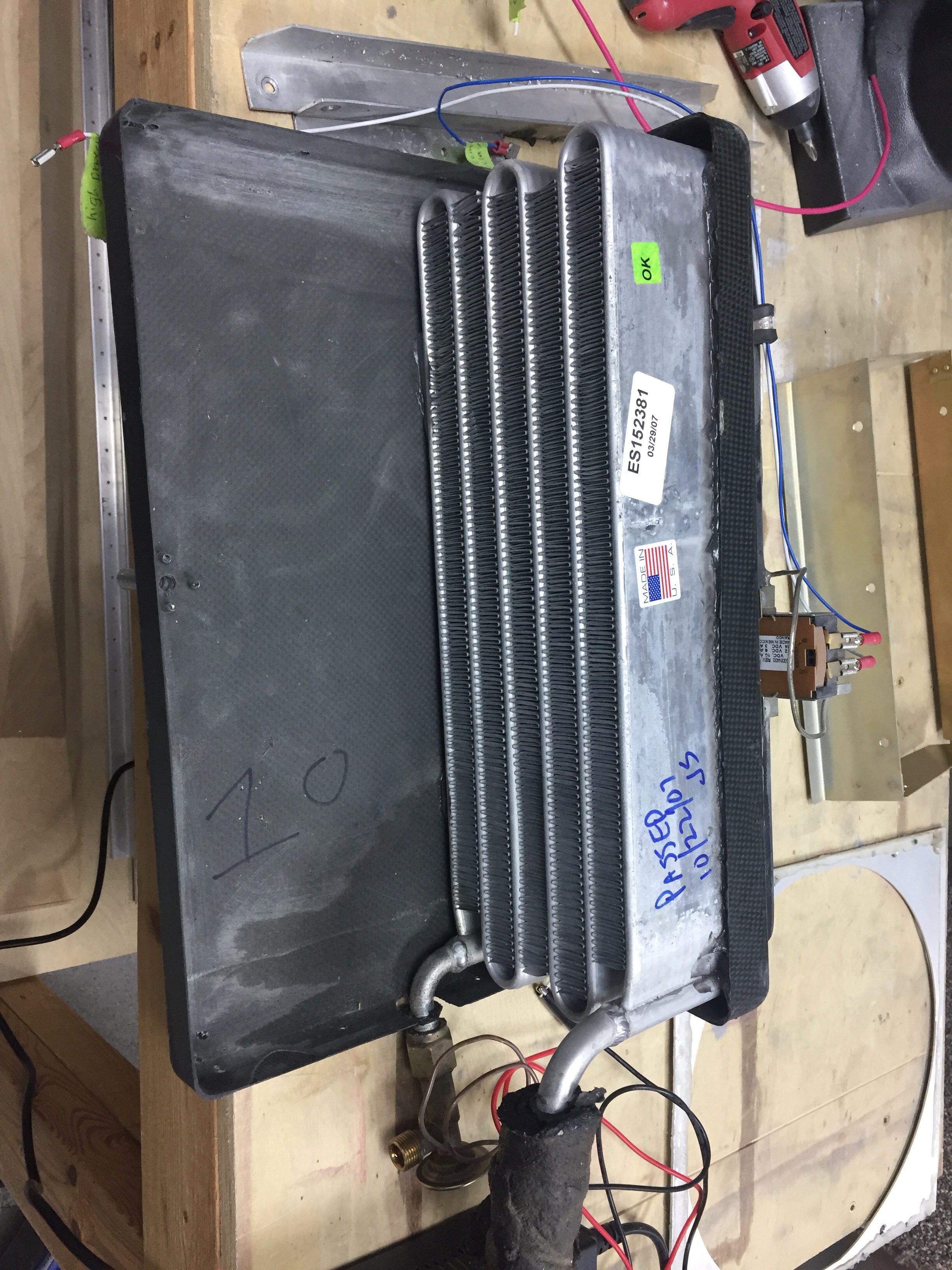
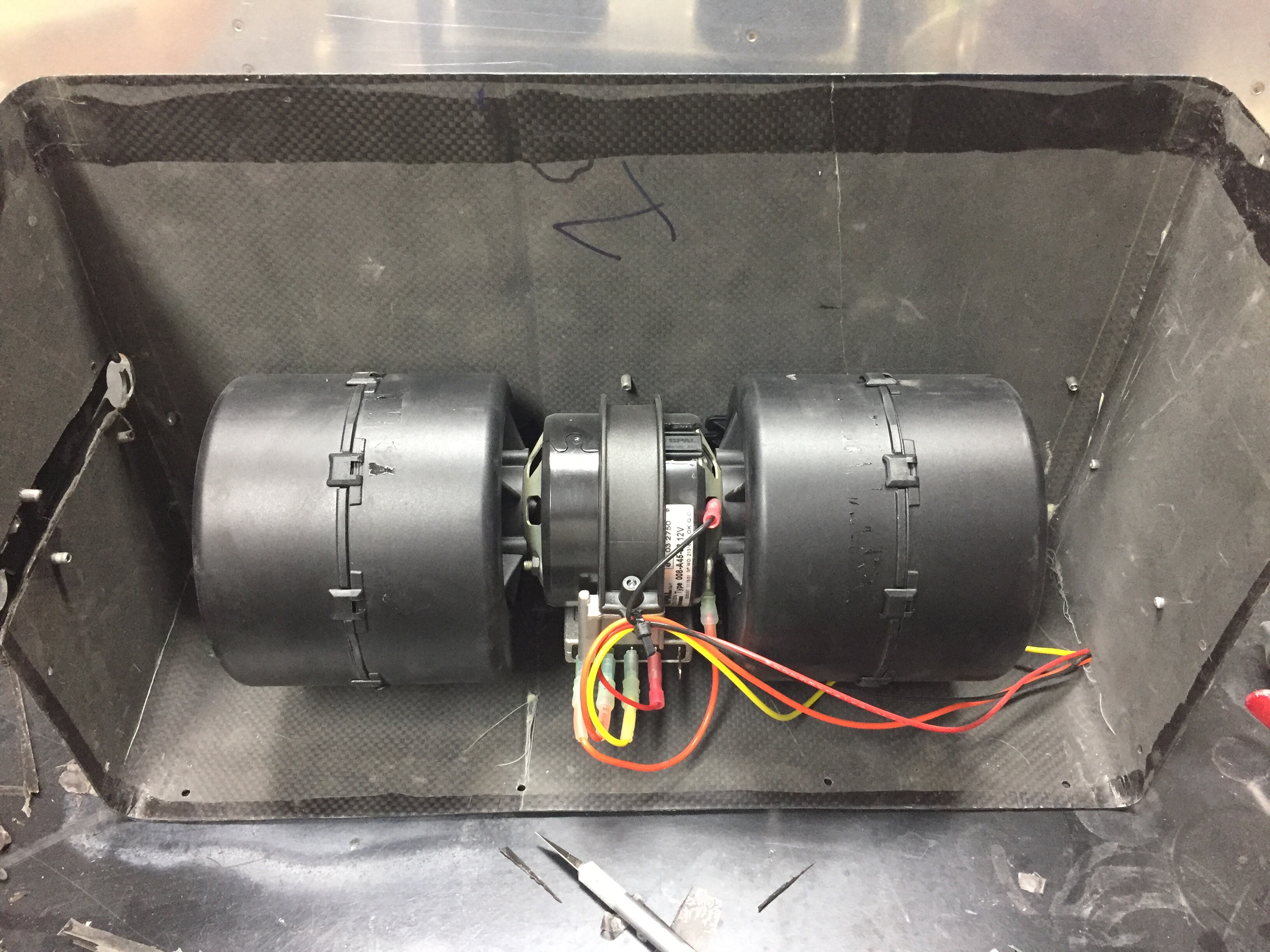
I took some extra time to silicone seal the assembly back together and made sure it was nearly air tight once complete again in the effort to increase efficiency. The equipment tray already had the mounting provided, so it was bolted back in and I went to work putting the flexible duct to the bulkhead supply duct headers.
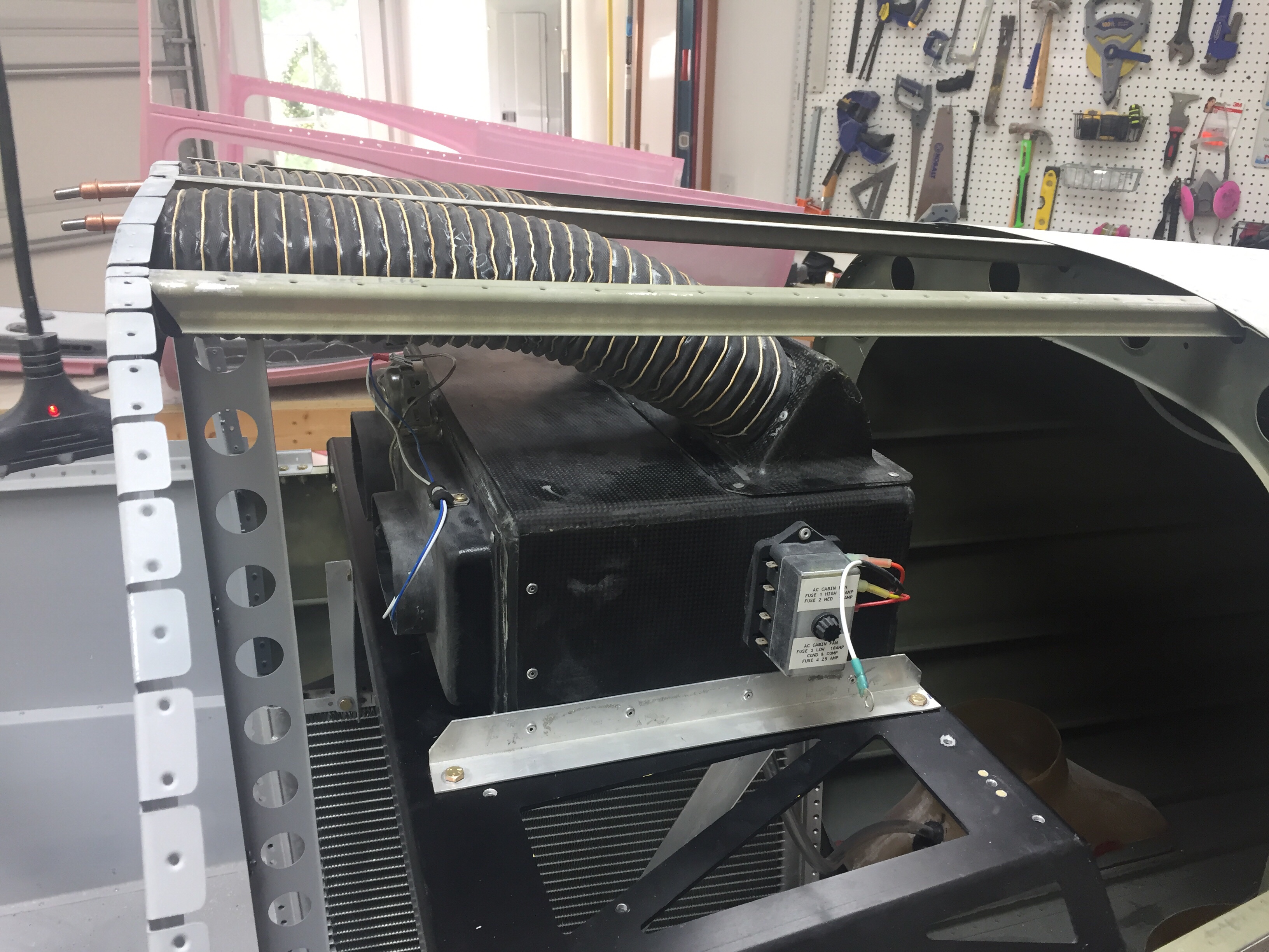
I’m ordering some thin worm clamps to clamp the ducting to the headers since the zip ties don’t really create a good seal.

After all said and done, this was a lot of work but it wasn’t terrible work. I’m very optimistic that the bones of the system will now work even better to provide cool air to the cabin and minimize the amount of attention the system will need over time. I still need to run the electrical and refrigerant hoses, which I’ll cover in a later post.

On a side note, I am still knocking little jobs off of the list such as the rudder cable fairings on the tail cone and a few other mundane tasks. Little bites at a time equal eating an elephant. Although you shouldn’t eat an elephant because you’d be a terrible person.
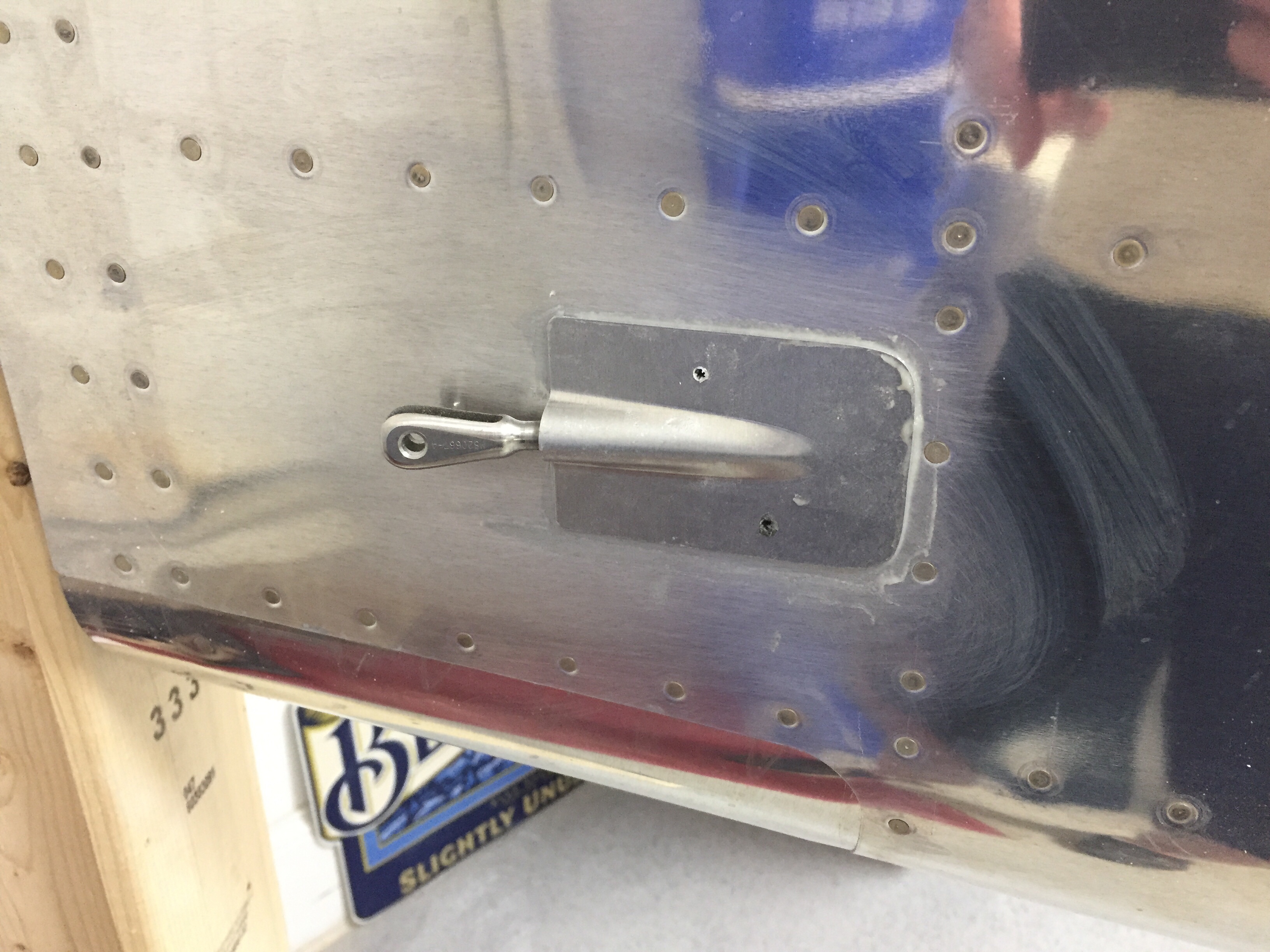
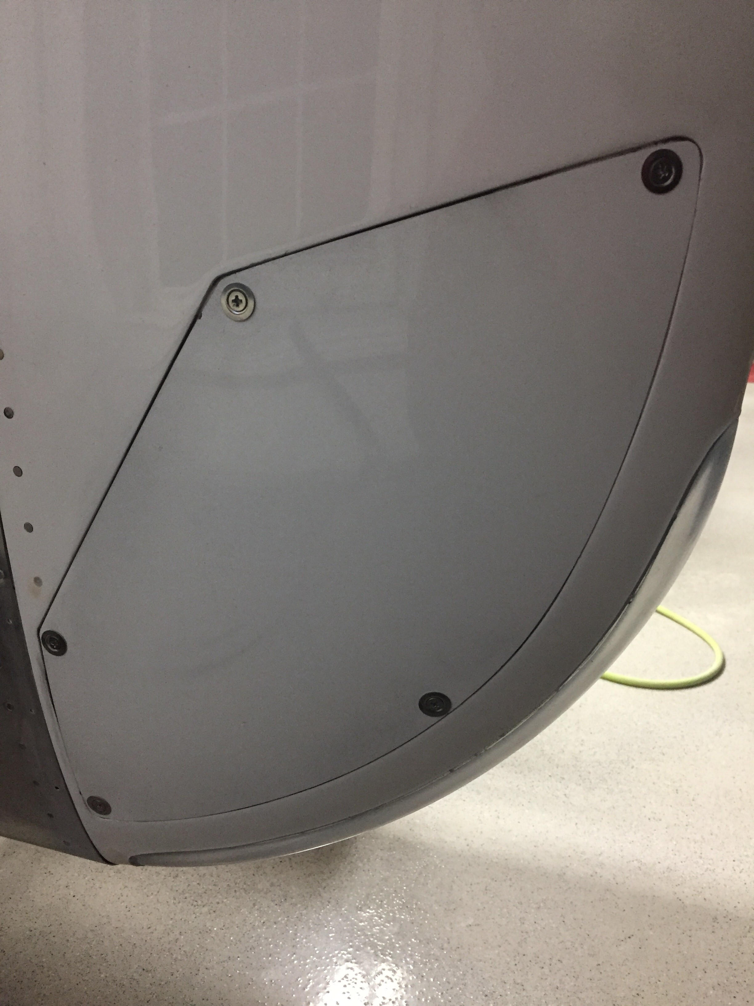
I also took out the stock intake and exhaust vents for the air conditioning and patched them using the original skin and backer plates made from the trim kit. I’ve finished that up by putting some filler in the cracks and smoothing it all out. It’s not perfect, but good enough for the bottom of the fuselage. If you’re judging my plane that much, you better have a rag and cleaner to wipe it down while you’re under there!
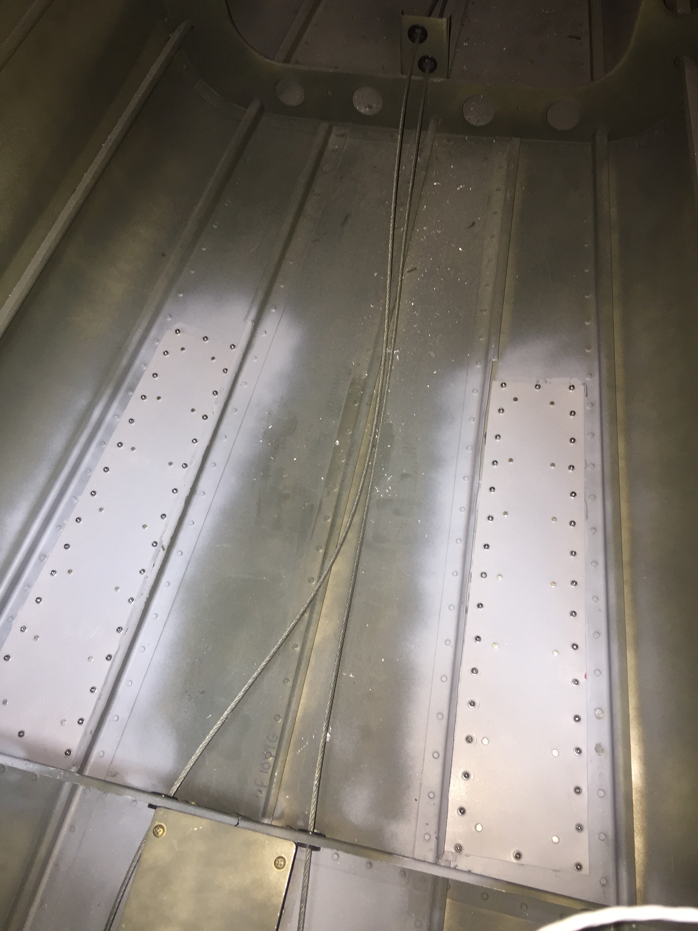
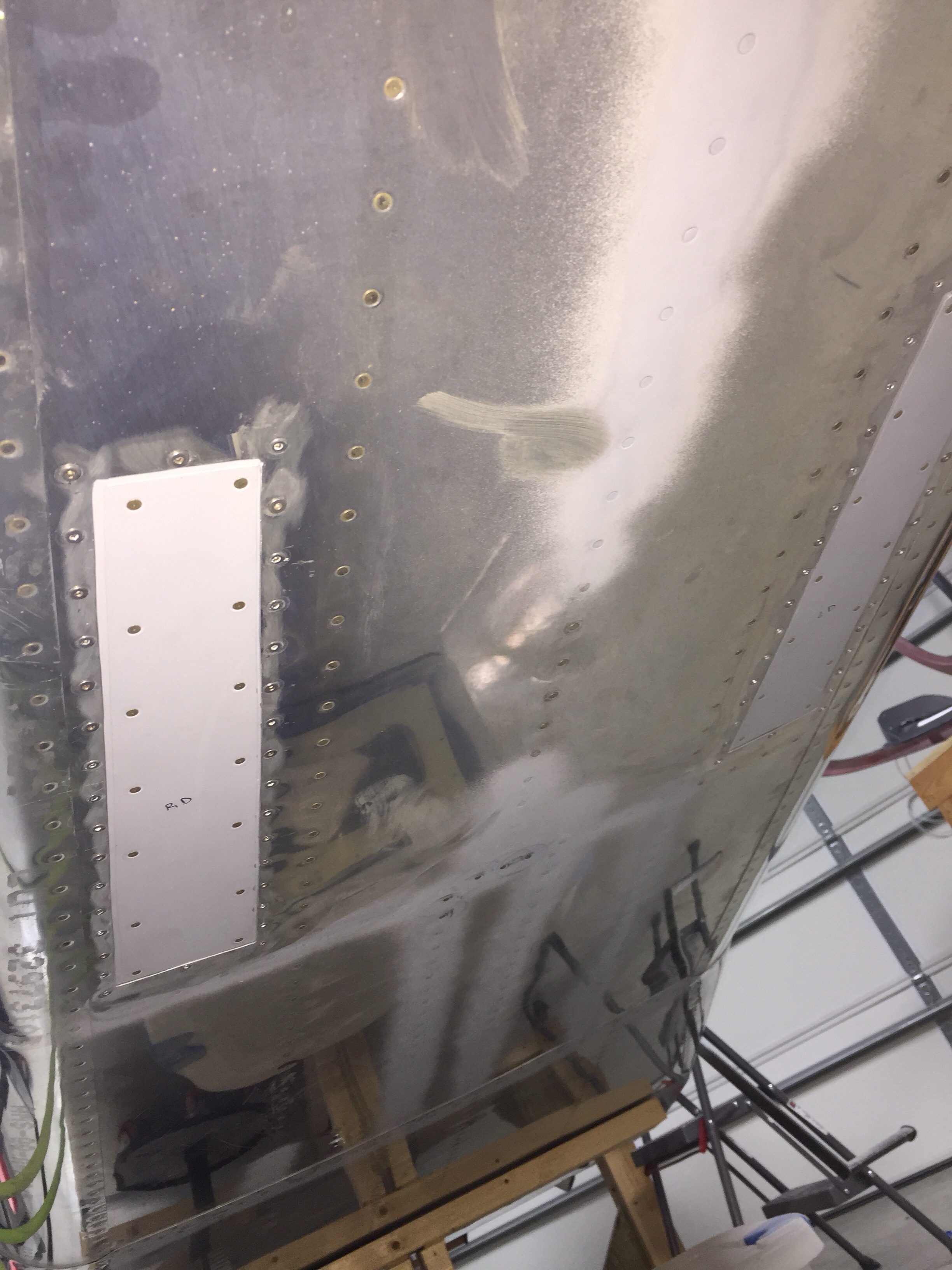
So I changed my mind, cool it.

I’ve been doing a lot of research and discussion with folks who have installed air conditioners, especially the Flightline setup like mine. The general consensus is that it’s marginally effective at best. My standards aren’t extremely high, as the AC in the Diamond we fly just takes the edge off but doesn’t really cool like a car would. Others with the Flightline system have added a second condenser and one or two have routed the intake from the bottom to the side skin to avoid the exhaust mixed heated air. As my original commitment to John at Flightline was to design a side intake and exhaust, I decided to dive in and redesign pretty much the whole dang thing.

First, an overview of the setup. An intake on the bottom tail skin catches air and directs it through 6″ flex duct up and 90 degrees forward where it turns 180 degrees and goes through a 12′ square condenser. A 12″ puller fan helps air flow volume so it doesn’t rely solely on ram air pressure. Then, it heads back into a 6″ flex duct, makes another sharp 90 degree corner and exits out the bottom skin. It’s a lot of direction changing and restricting of the air.

I began by taking everything apart and checking out how it was all pieced together. The first thing I noticed was the mounting plate for the fan actually covered a 1/5 or so surface area of the condenser. Additionally, the system didn’t use basic air velocity and volume principles, so it was constantly going from small to large volume spaces with many restrictions.

My goal was to facilitate air flow through the shortest path with the least resistance, thereby providing more efficient flow and better heat exchange in the condenser. I studied several factory AC setups such as the Cirrus, Bonanza, and M350 and noticed no ducting on the intake and direct exhaust from the condenser through the skin. The condensers were also significantly larger in surface area. So the new design would be to pull ambient air from the tail cone through a larger condenser via the same fan and exhaust it through the side skin within the shortest path possible. The ambient air is provided through an louvered intake near the horizontal stabilizer.

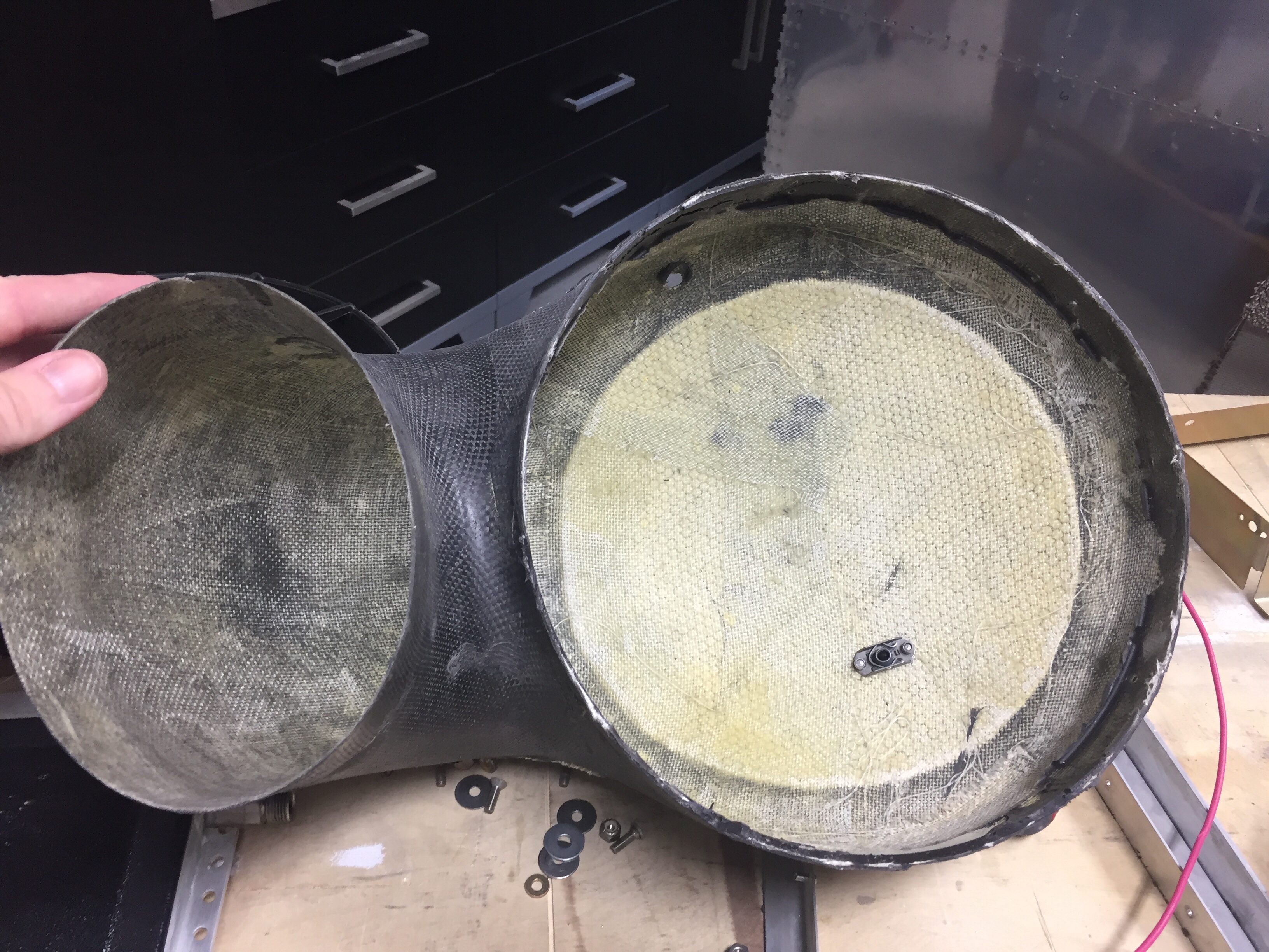
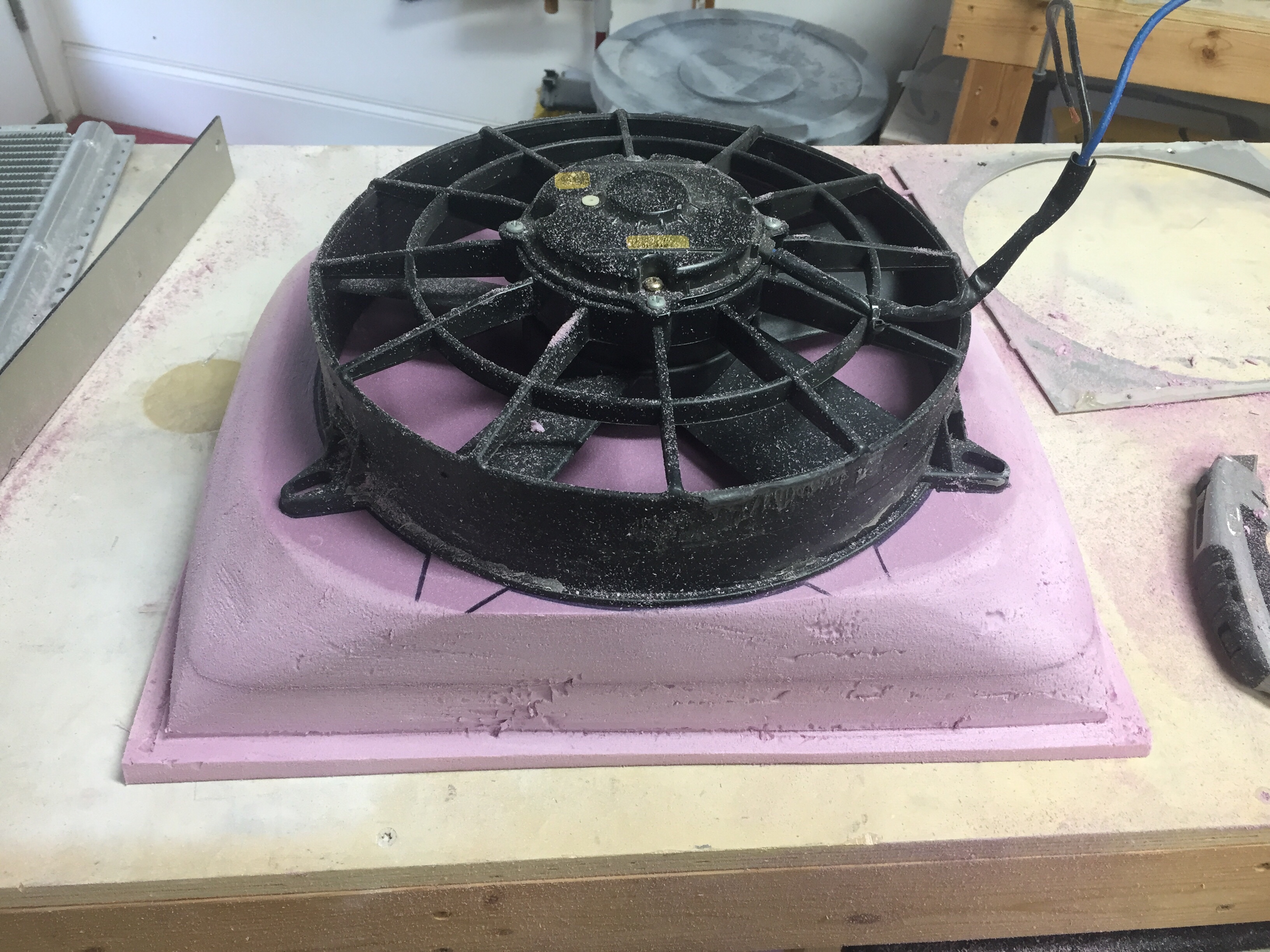
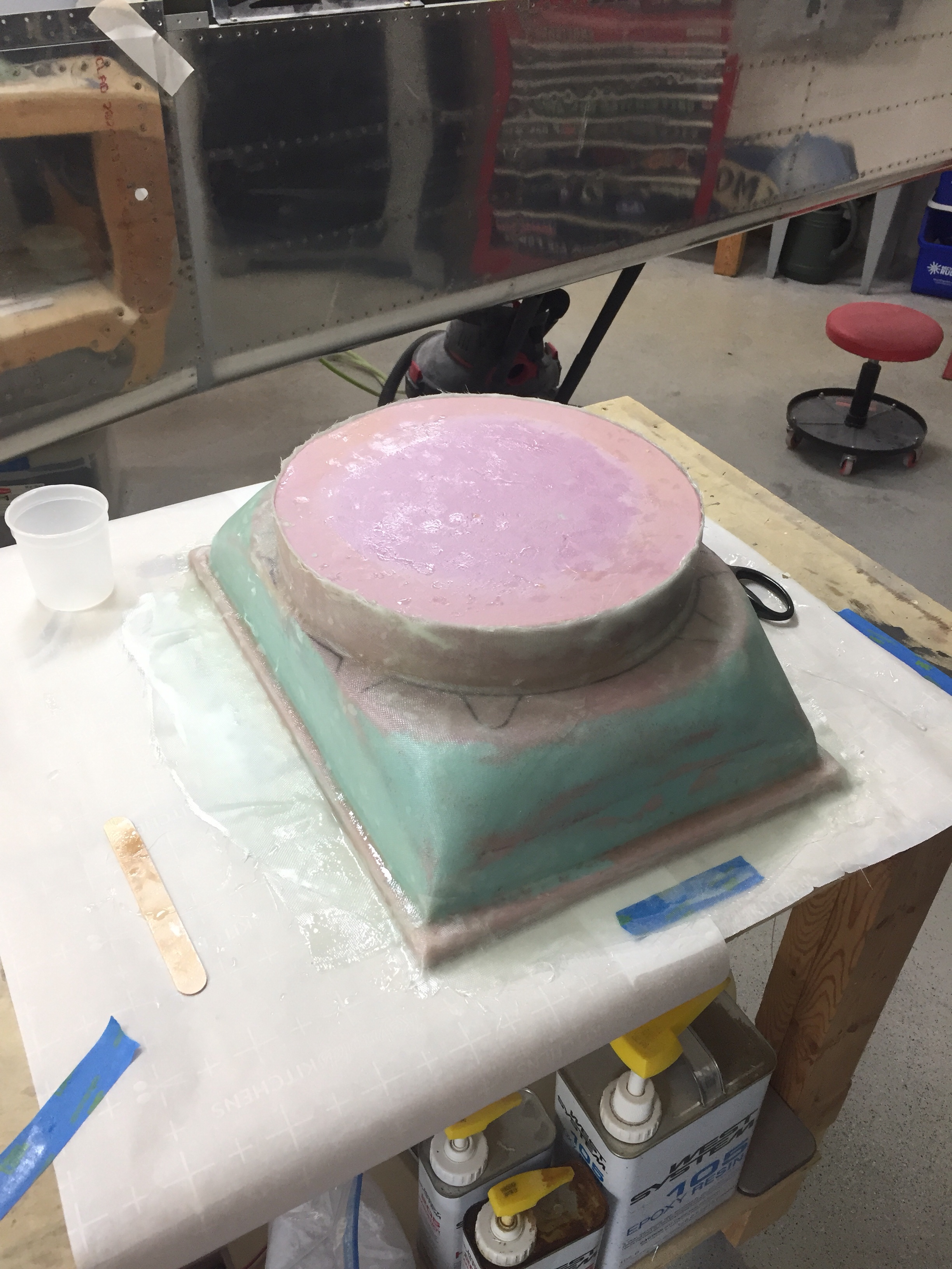
So, I bought a 16″ x 12″ condenser and set about molding a plenum from the condenser to the fan. If I had a vacuum table, this would have been perfect to keep the mold to share with others, but unfortunately I had to lay up fiberglass and the molds were trash.

The layup came out very nicely despite destroying the mold and was a perfect fit around the fan casing. A simple bead of silicone should seal it up nicely when installed.

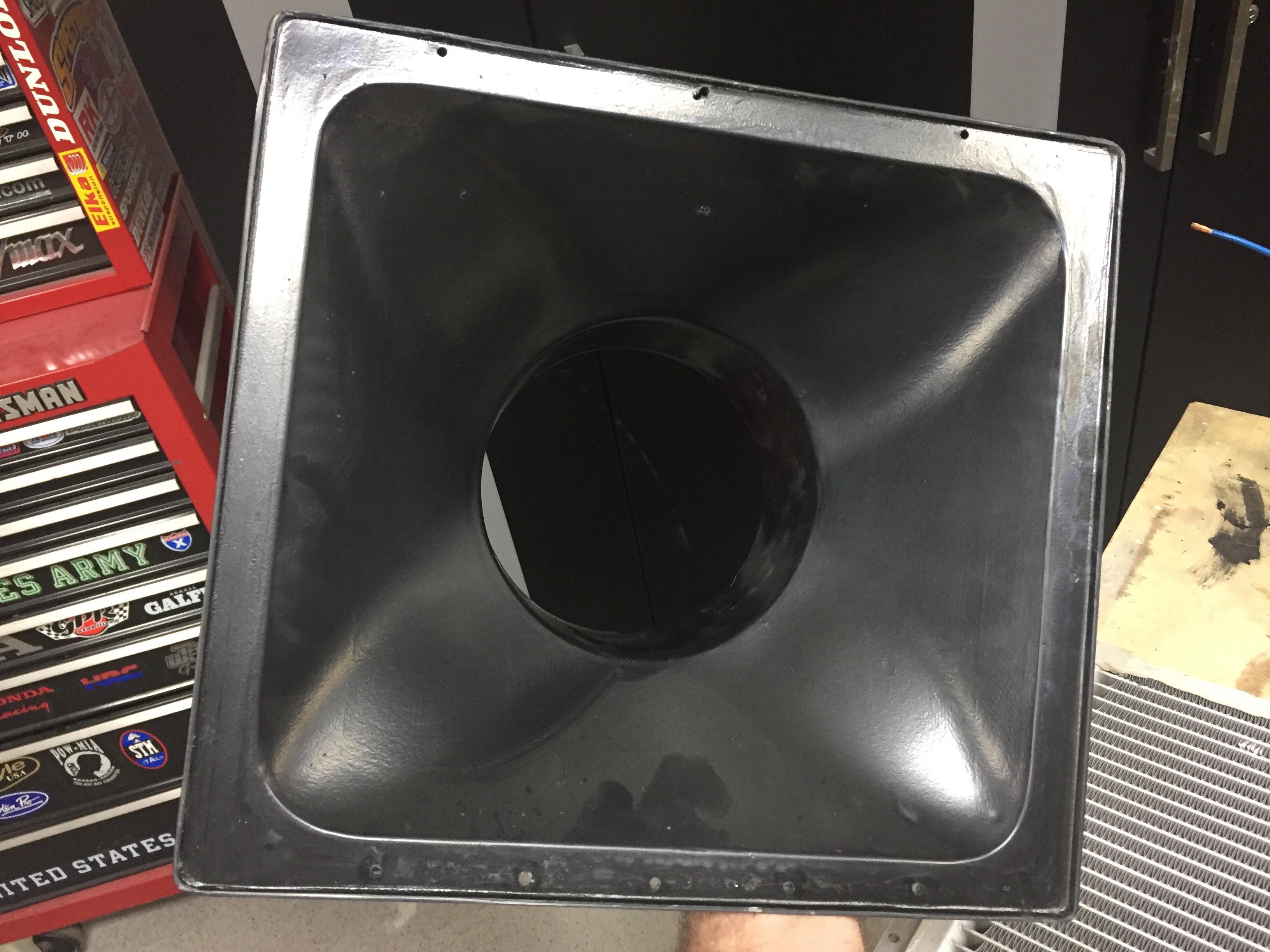
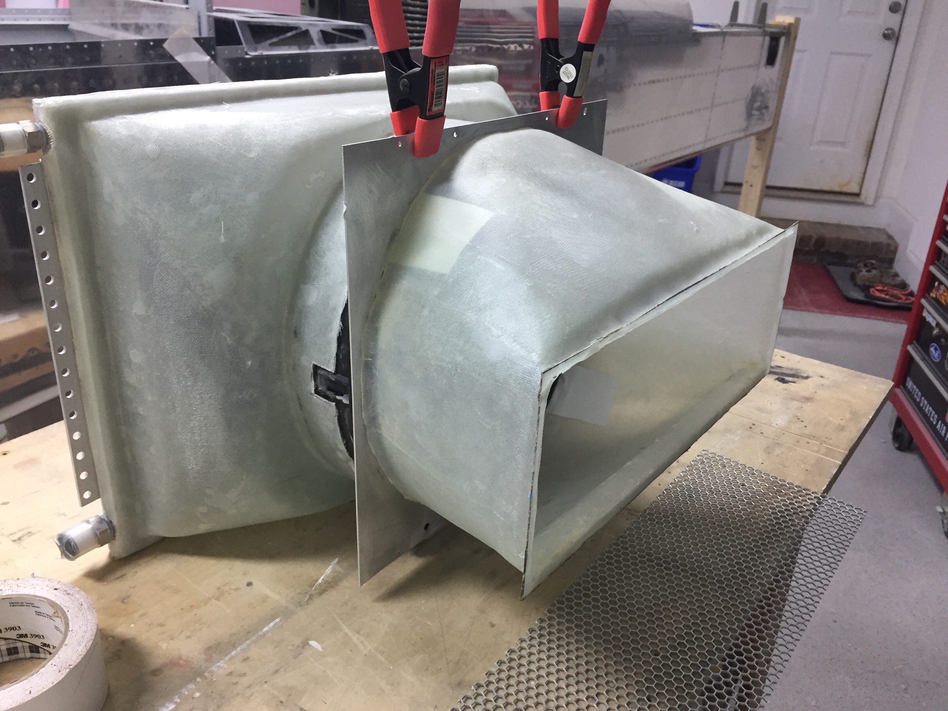
Next was to do a mold from the fan to the skin for the exhaust. I figured up the square inches of the fan and worked within the stringers to maximize the opening area while keeping it just under the square inches of the fan. My thought on this is using the Bernoulli principle and having the smallest (relative to the entire air path) opening creating the highest velocity at the skin. This will in theory help the exhaust penetrate the boundary layer air around the fuselage, which has also been a concern from others.

I used the same fan mounting plate since it’s no longer restricting air flow. The exhaust plenum as a lip molded in to use as a mounting surface on the skin. The weight of the setup will be supported from the stock tray so the plenums aren’t load bearing.

I put it all together and hooked up the fan to check it out. There is significantly more air flow going through and I’m cautiously optimistic that this will create a much better performing system.

Next up will be mounting it all in the airframe and cutting the skin.

Controlling the overhead

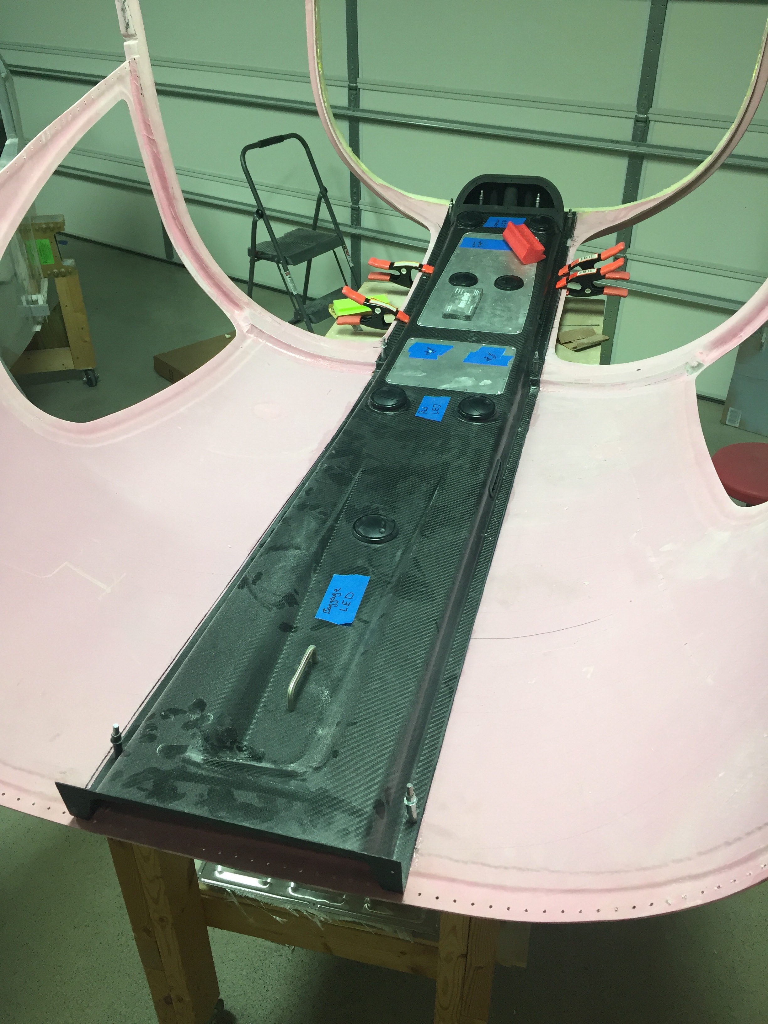
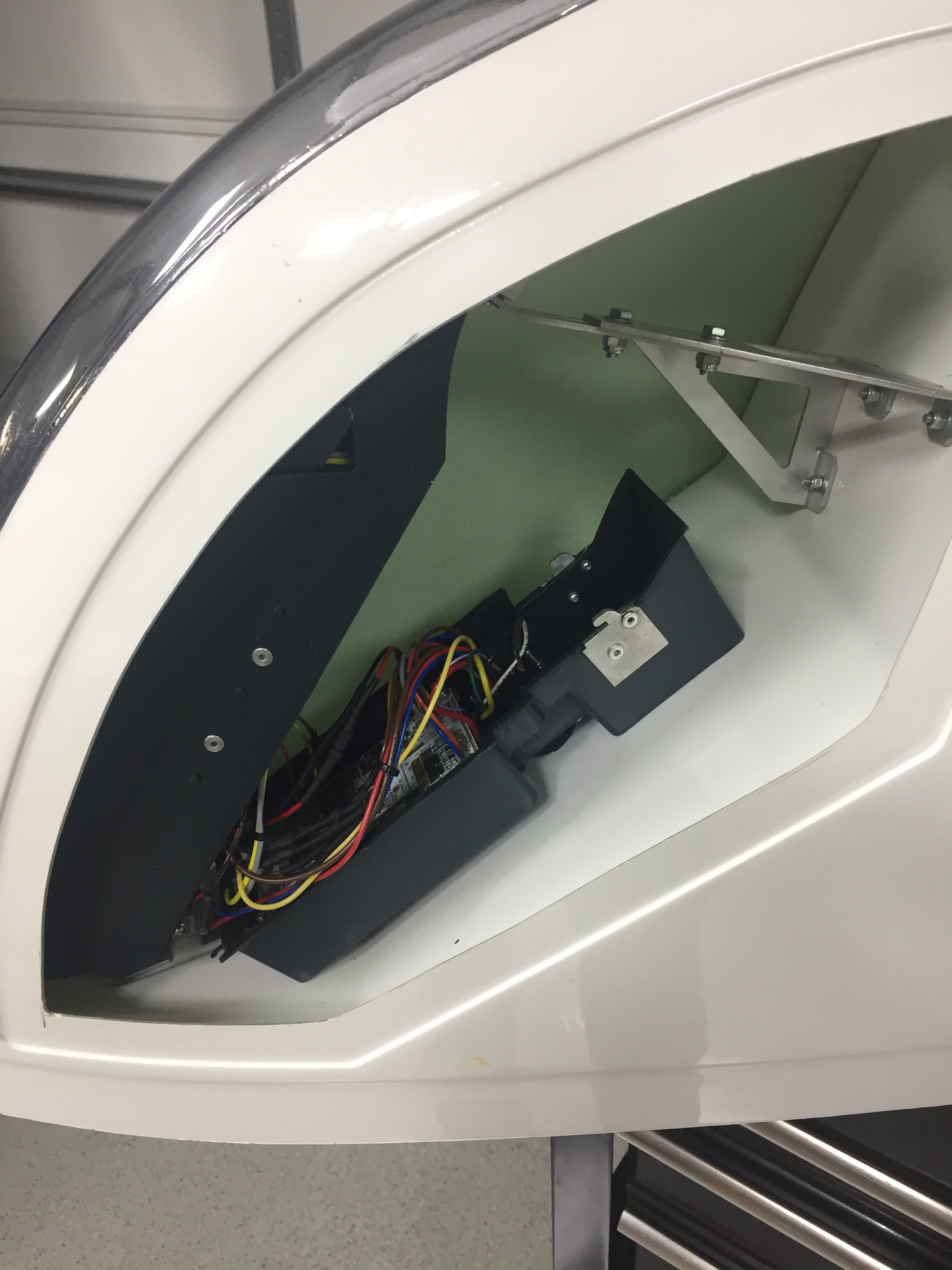
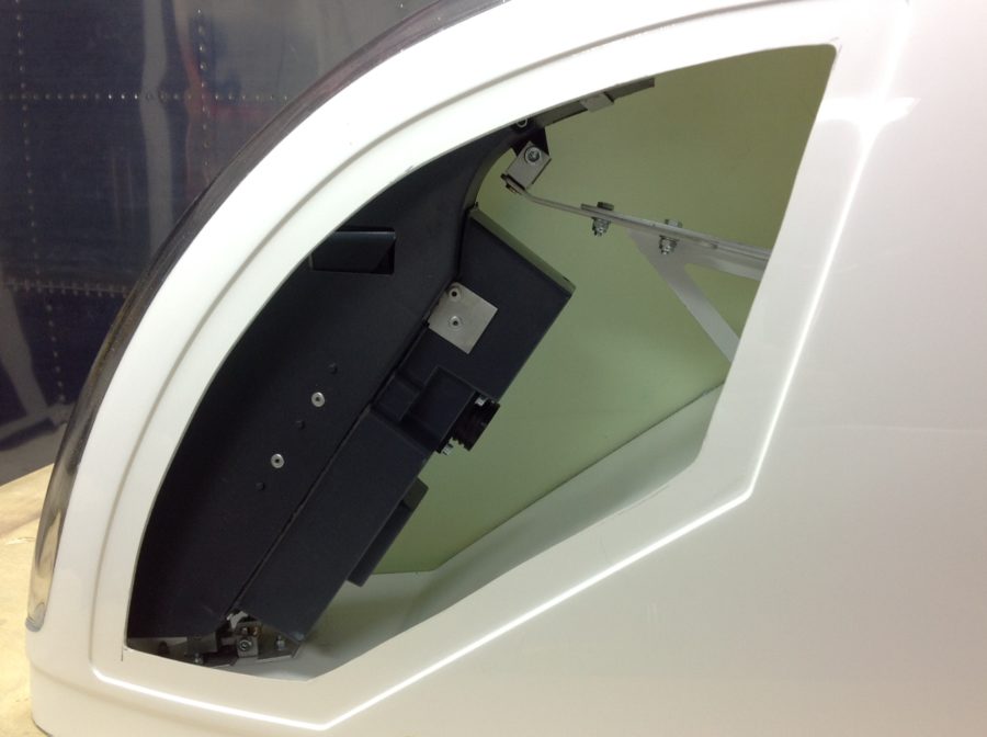
One huge task to complete before the cabin top can go on for good is the overhead console. This piece of art comes from Aerosport and allows the vents for the air conditioning and the lights to be mounted on the cabin top. I also have one of the first production examples of the overhead switch panel that Ed Krantz molded up.

The first step is a rough fit and trim to get an idea where the interference points are. The mold they use is pretty accurate but has a few spots that needs adjustments. I didn’t have to cut the joggle around the step in the cabin top, however, there were a few spots up near the windshield that were too bulbous and had to be ground down. Overall, the initial trim and sanding was a pretty quick and painless job.

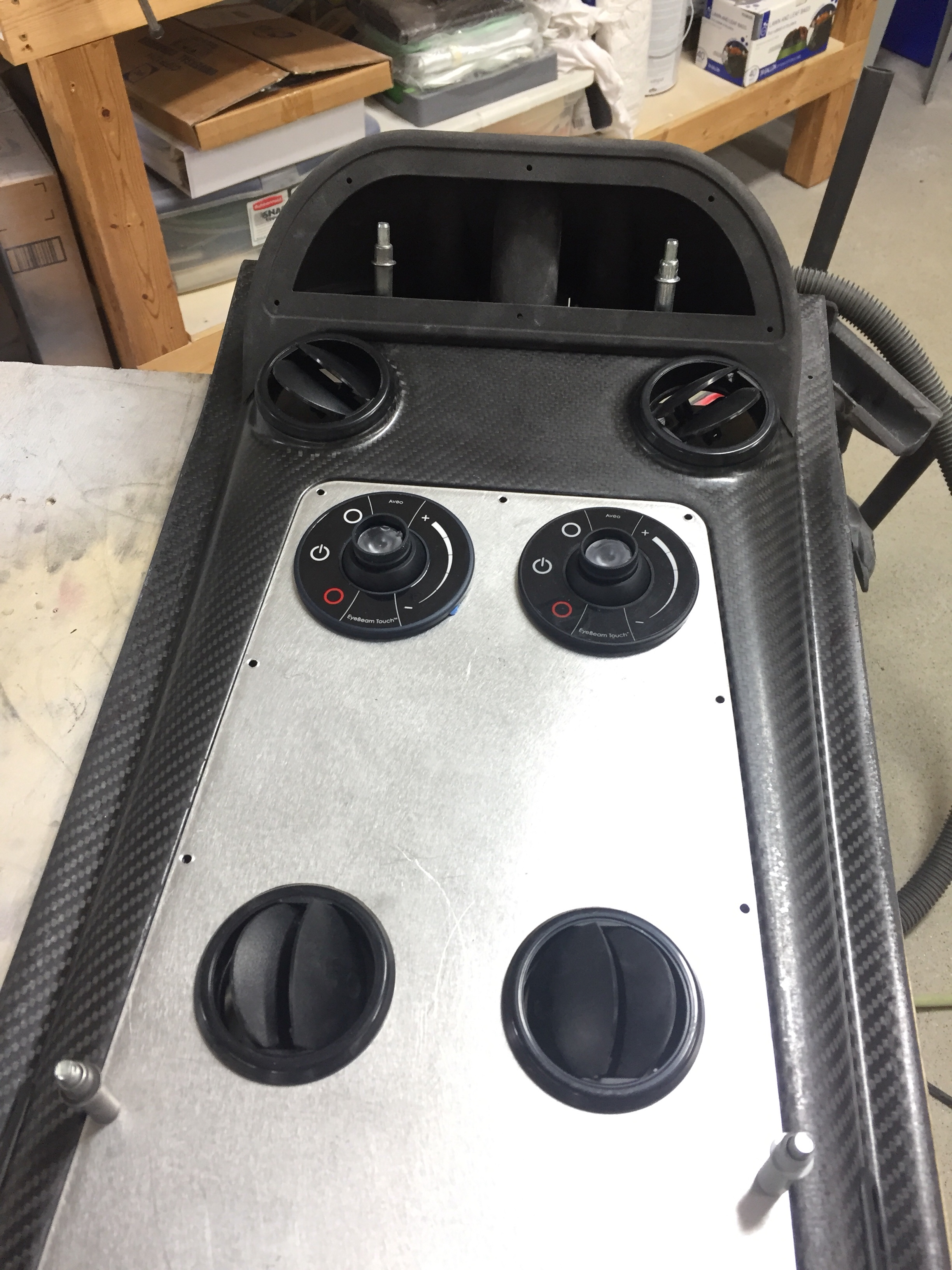
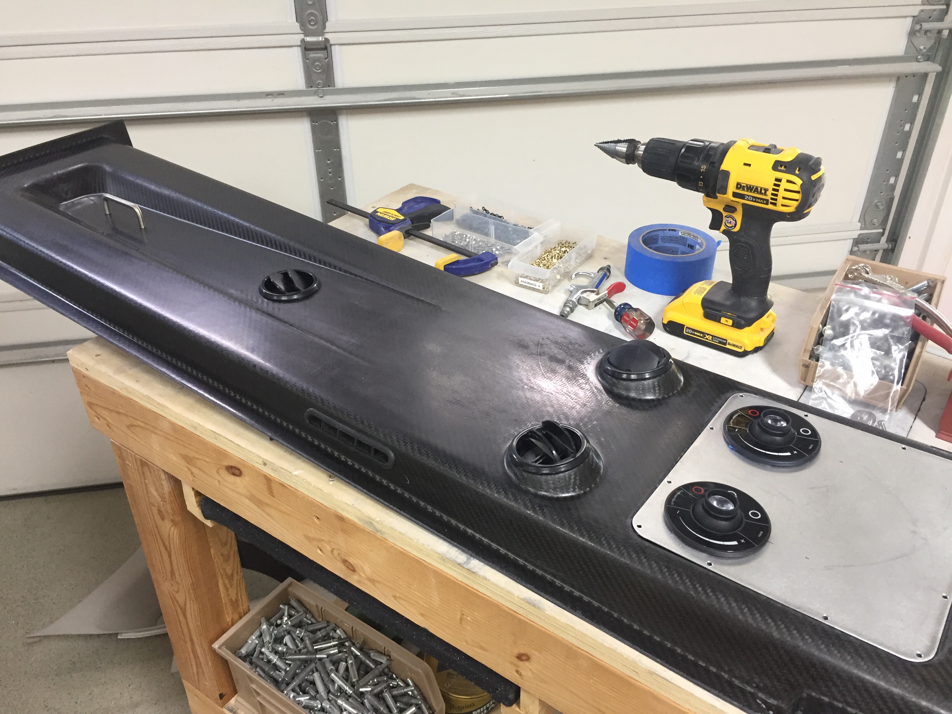
The overhead has two large aluminum panels that can be used for lights, vents, etc. but need nutplates installed to secure them. Pretty quick job to set it all up including countersinking the panels for flush screws that came out very nicely. I also decided where to mount the four curtain vents that I got from South Florida Sport Aviation. They are using the Airflow Performance set up on their own interior and despite my best efforts, I couldn’t find any vents like these online. I like these because it allows good airflow along the windows as well as alternate airflow if one or more of the vents are closed, keeping good flow through the cabin and over the evaporator which is key to efficient performance of the air conditioner.

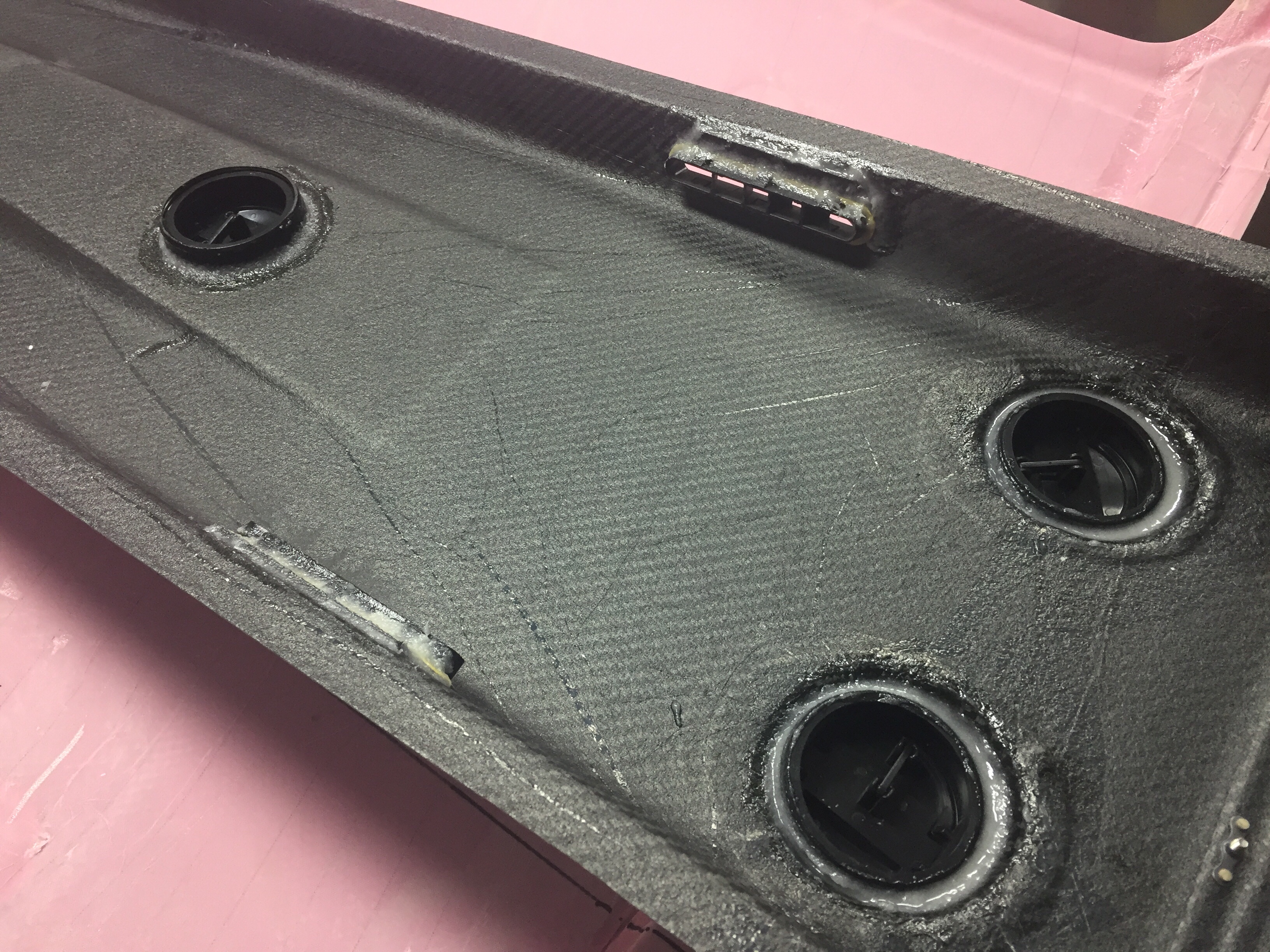
I also used the four molded spots to mount air vents in as you can see the cutouts above. Most have used either the eyeball vents or a universal car vent. Based on feedback from others and the astronomical price of eyeball vents, I decided Summit Racing vents would work better. They were $20 each instead of $120 each and I think will allow a lot more air to flow while being easier to use. I simply used epoxy/flox to secures them to the overhead taking care to not have any leak on the vents themselves. I also put two vents in the metal panel so that the pilot and copilot each have two vents, hopefully keeping me cool up front with all the glass. The panels will also hold an Aveo Eyebeam Touch task light for each seat.

Lastly, I installed the coat hanger in the rear which will probably rarely be used, but hey, it’s part of the kit and looks good. I can also use it to call this a business aircraft!

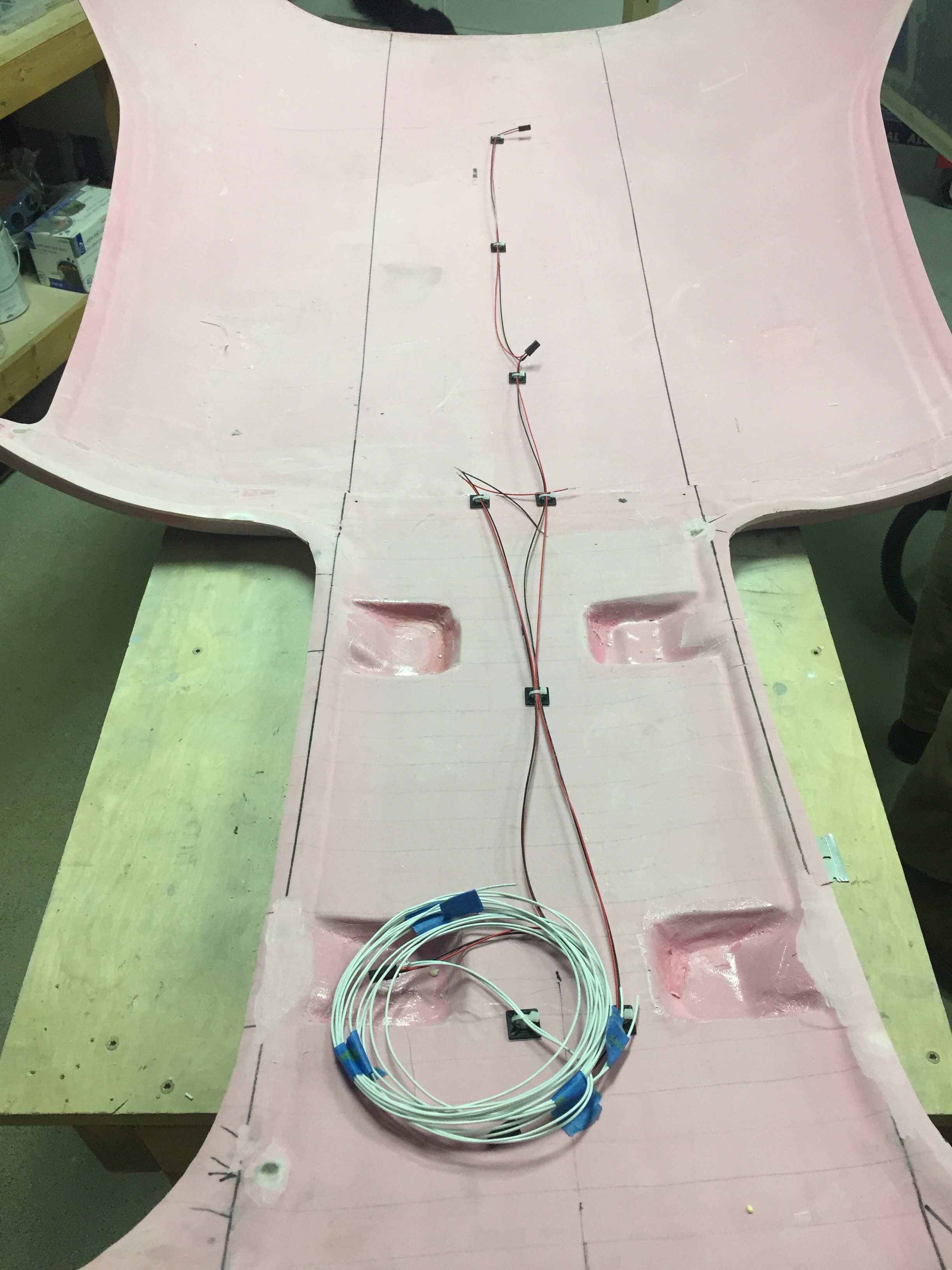
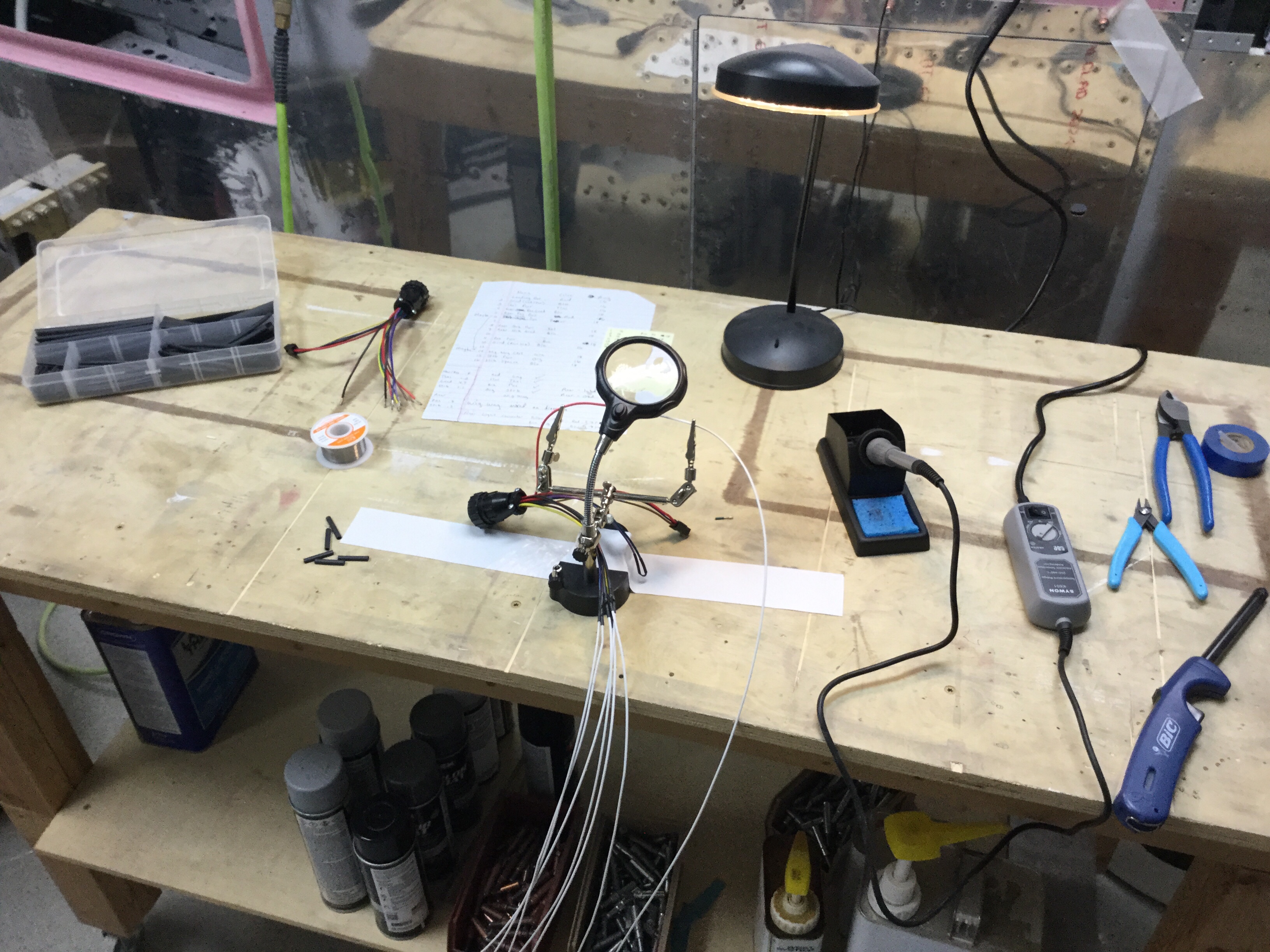
I will be running the wires for the switch panel and the task lights up through the center post so wanted to get the wiring that will be in the overhead completed. I went ahead and made up the wiring harness for the four task lights as well as the three overhead dome lights that will be used for general cabin lighting. The pictures show bare contacts, but after another order from Mouser came in, I installed the Molex connectors so that everything is line replaceable without cutting wires. I also cut the three holes in the overhead for the lights.

Finally, after one complete evening off of the cabin top to clear my head and make sure I’m not forgetting anything, it was time to epoxy it on for good. I mixed up a healthy amount of epoxy/flox and fortunately had a friend to split the task of spreading the mixture and setting it in place. With a couple of clamps and clecos, it fit well and made a secure bond to the cabin top.

Next up will be shaping and filling the assembly to get it all prepped for paint and final instal.

Wired for moving day

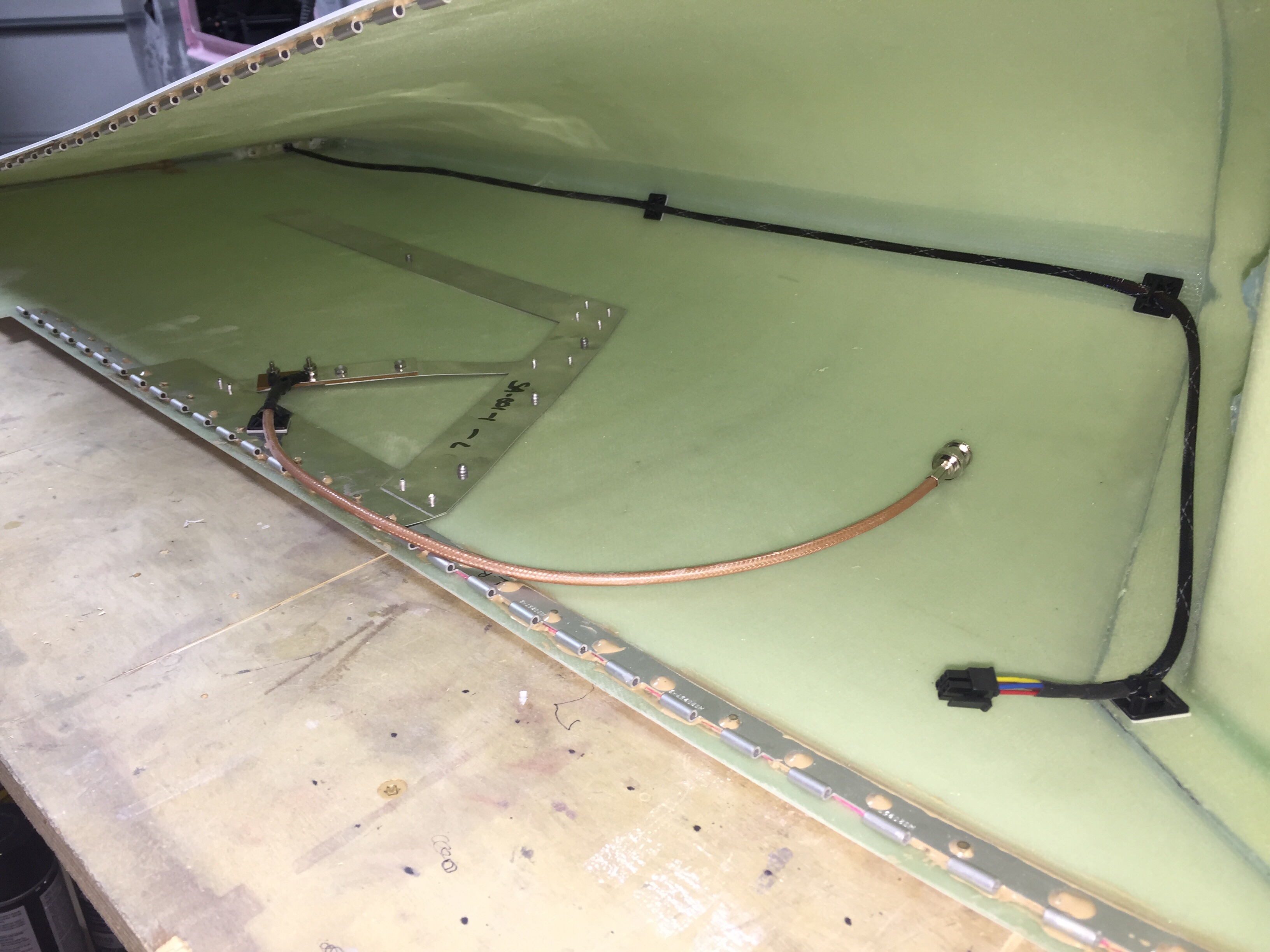
With the tips fitted to the wings, it’s time to run some wiring and finish up the wings. I integrated the Archer nav antenna into the tip mounting hinge which thus links the antenna to the wing for a proper ground plane, per the plans. I used a few pop rivets through the bottom of the tip to secure the antenna in place. I wanted to make the tips easy to remove, so I used bulkhead BNC fittings for the coax on both end of the wings.

I also ran the wires from the trailing edge position / strobe light up towards the main lighting modules and installed a micro fit connector so that the lighting module can be removed for future maintenance / replacement should the need arise. Again, all of the wiring has been documented in Visio including pin outs on each connector so I’ll be able to reference it long after I’ve forgotten how or why I did it this way!

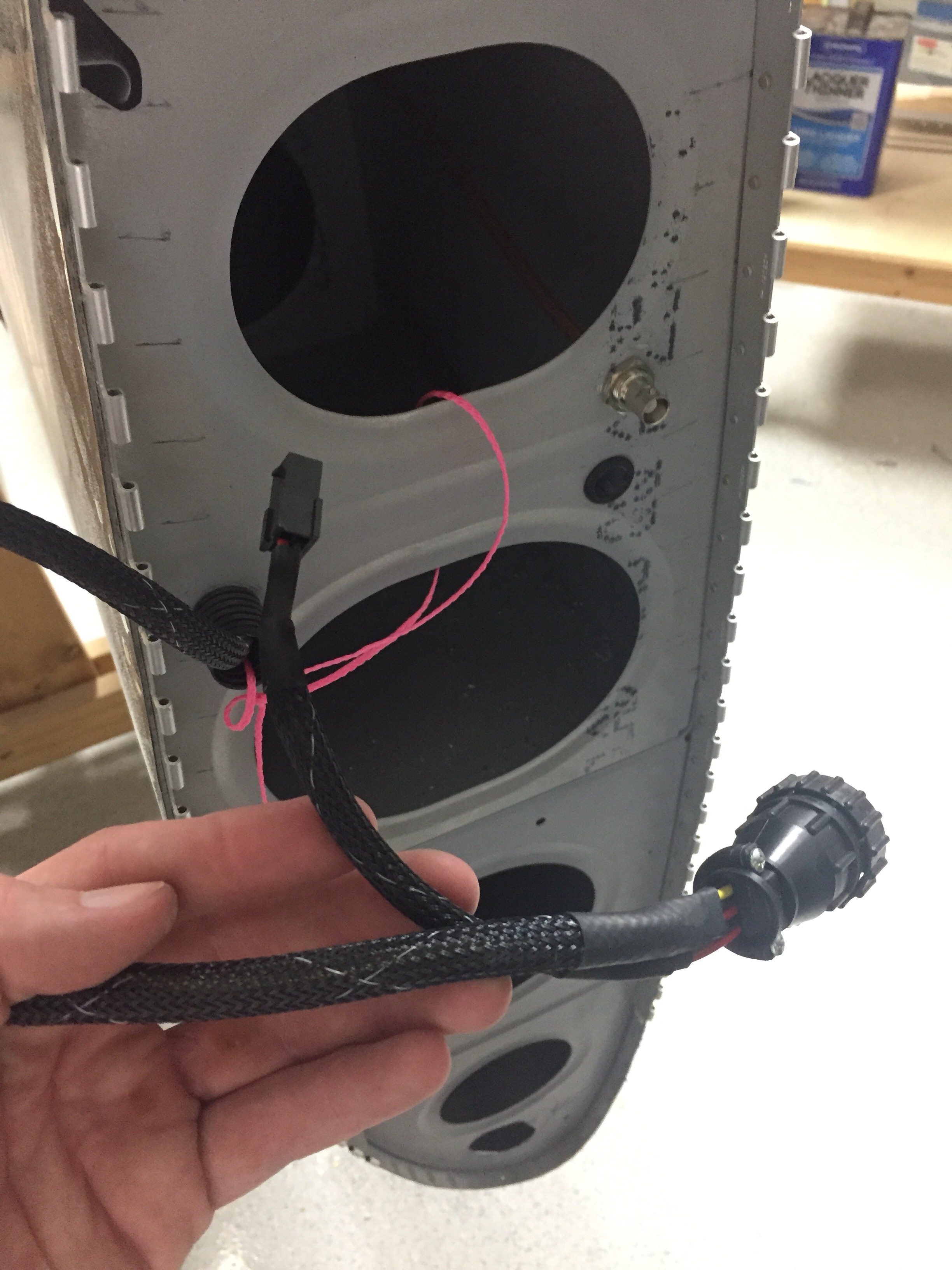
I used CPCs for the main wiring runs and am very pleased with the setup. Some folks avoid connectors like the plague, but I don’t see them as failure points if they are done right and properly tested / treated. I checked continuity of each wire after running them all so I know everything is ready for plug and play. The wing root connectors include those for the pitot heat and AP servo on their respective wings. The aileron trim servo is on it’s own micro fit connector due to the small wire size. I’ve gotten really proficient at the micro Molex connectors and really like them.

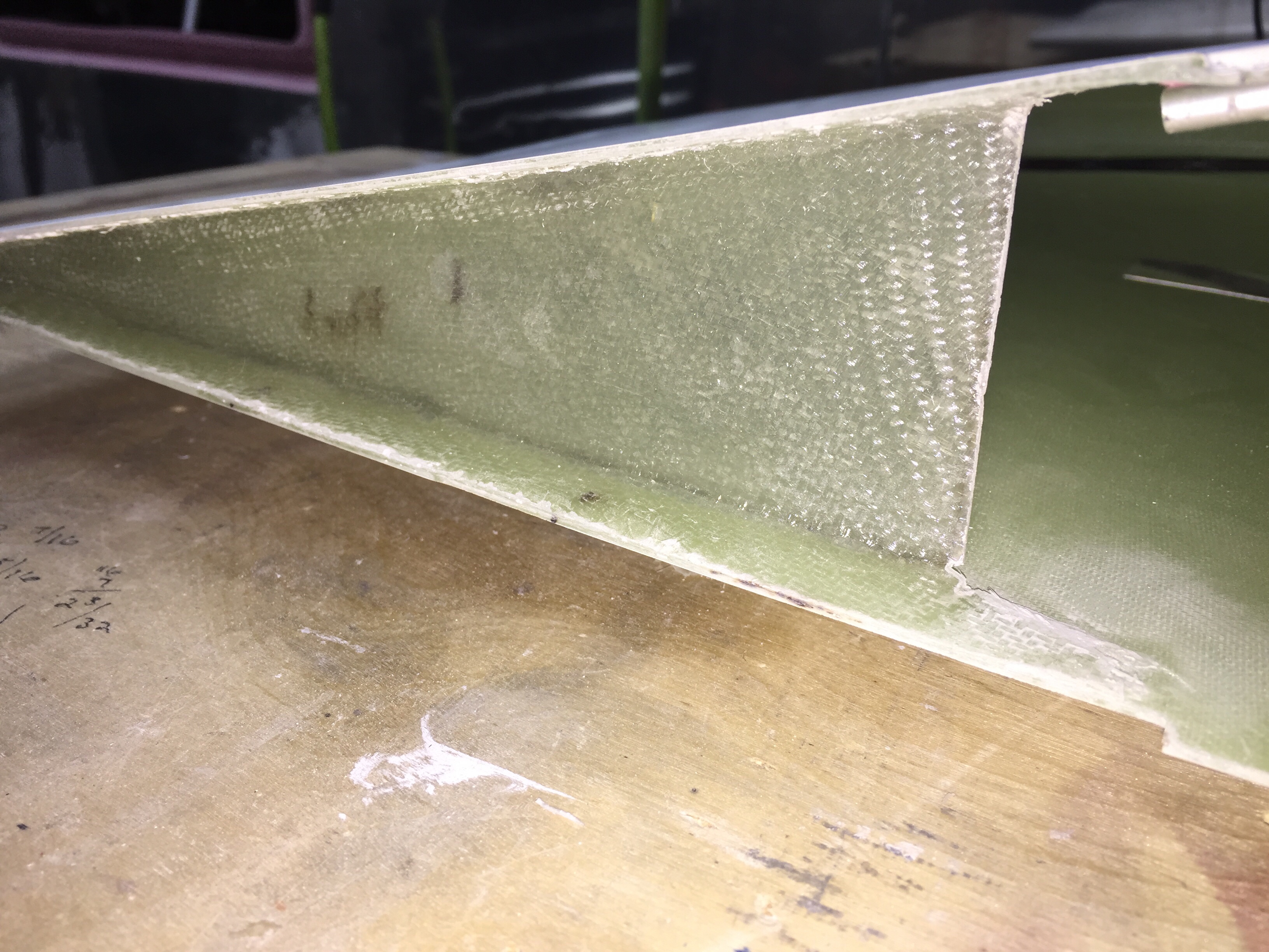
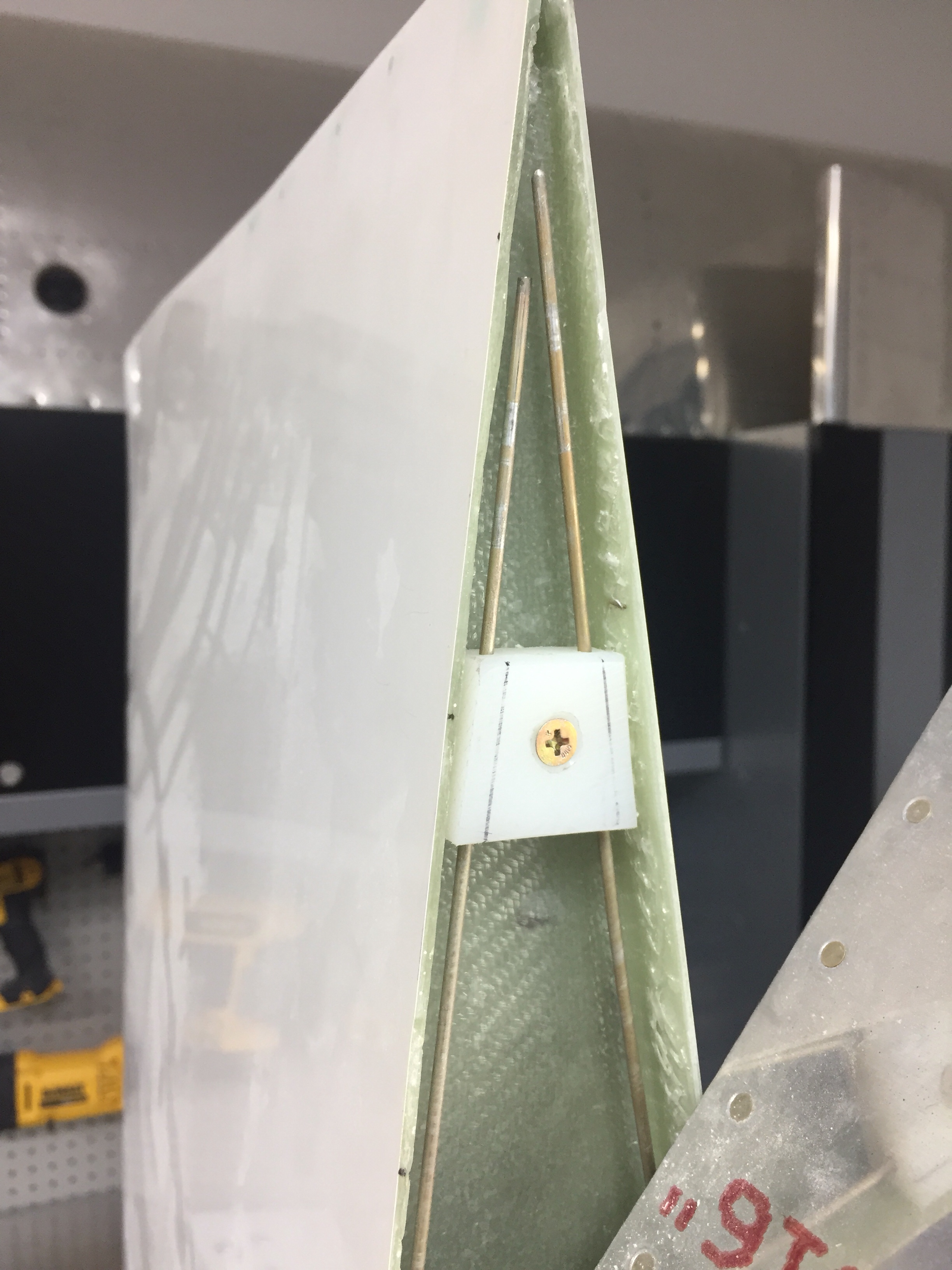
I also had to layup a small rib on the trailing edge to not only support the shape of the tip, but also provide a mounting surface for the hinge pin retainer. I used a trimmed block of delrin and nutplate to secure the pins. This keeps the pins inside the tip profile and thus unable to work themselves loose. They also butt up against a stop on the leading edge. I didn’t want to put a bend in them, as it’s very easy to use a drill and spin them in / out.

The only system component not installed in the wing is the OAT sensor which I’ll get with the avionics in a few months. That’ll be simple to put into an access plate and a string is still waiting to pull wires through the wing root.

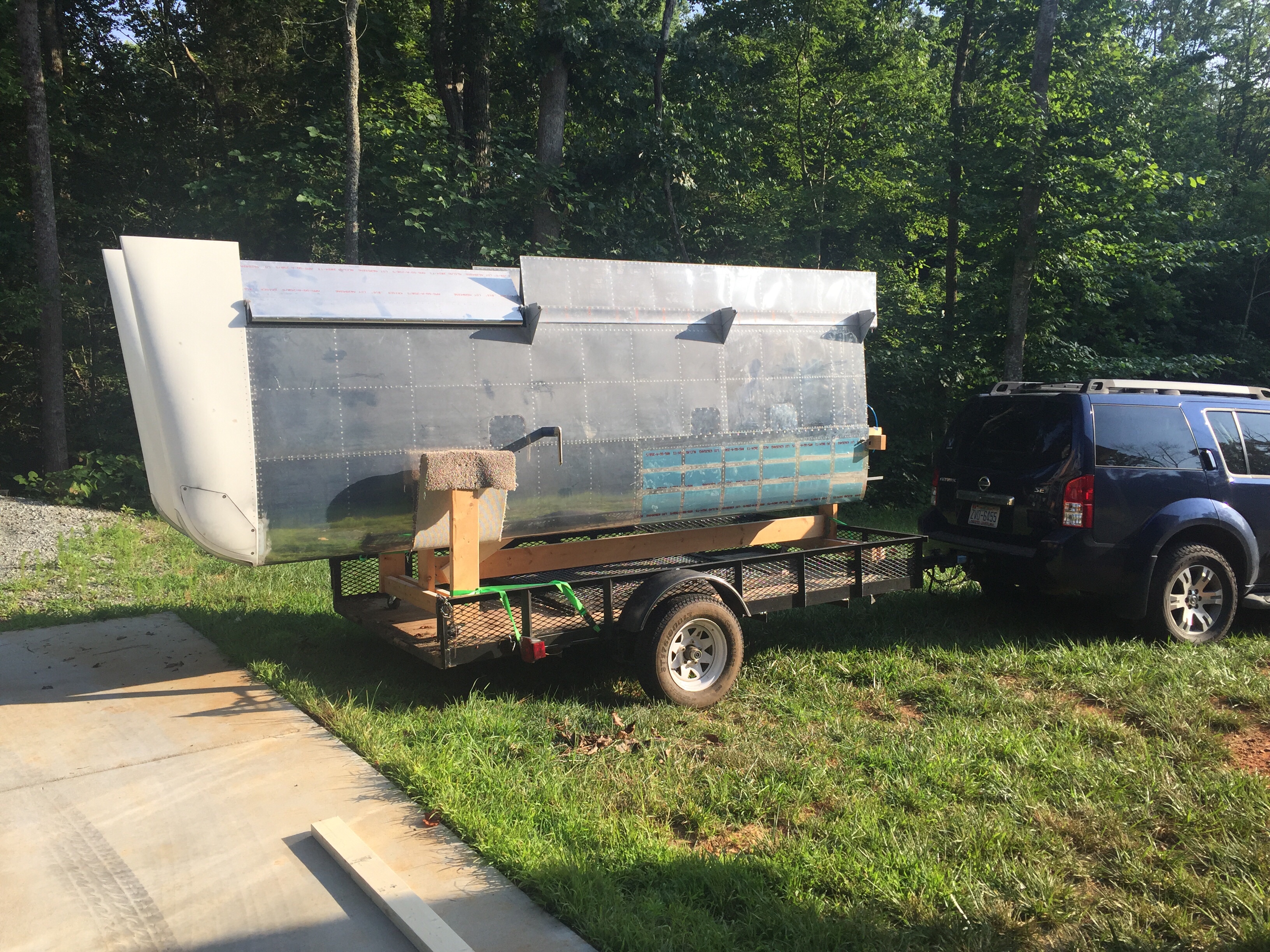
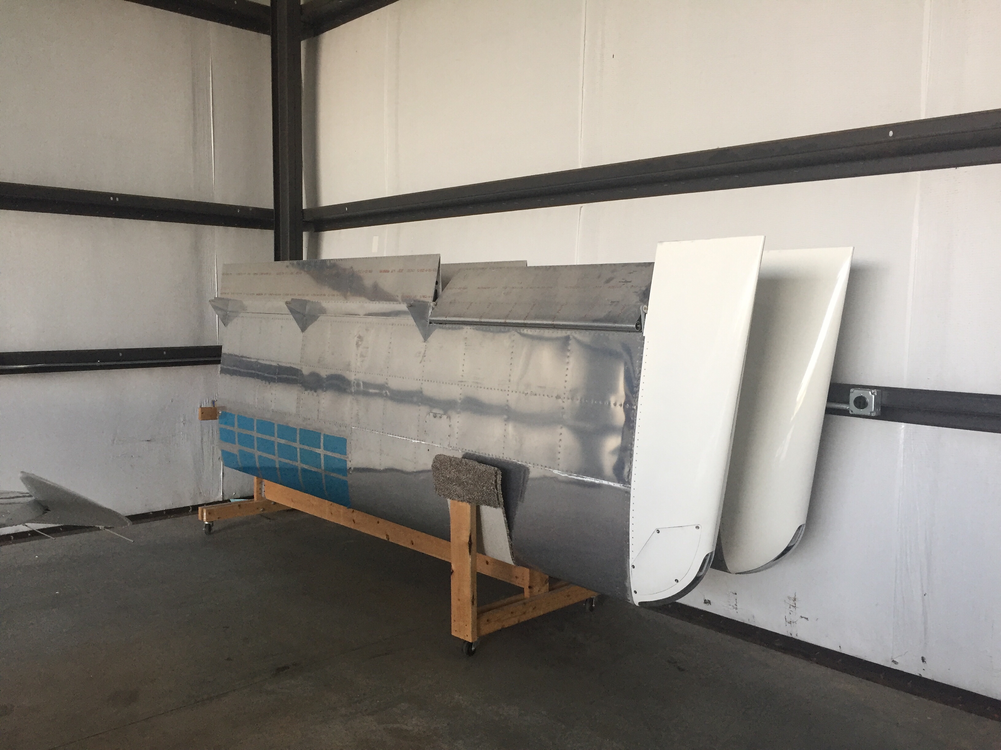
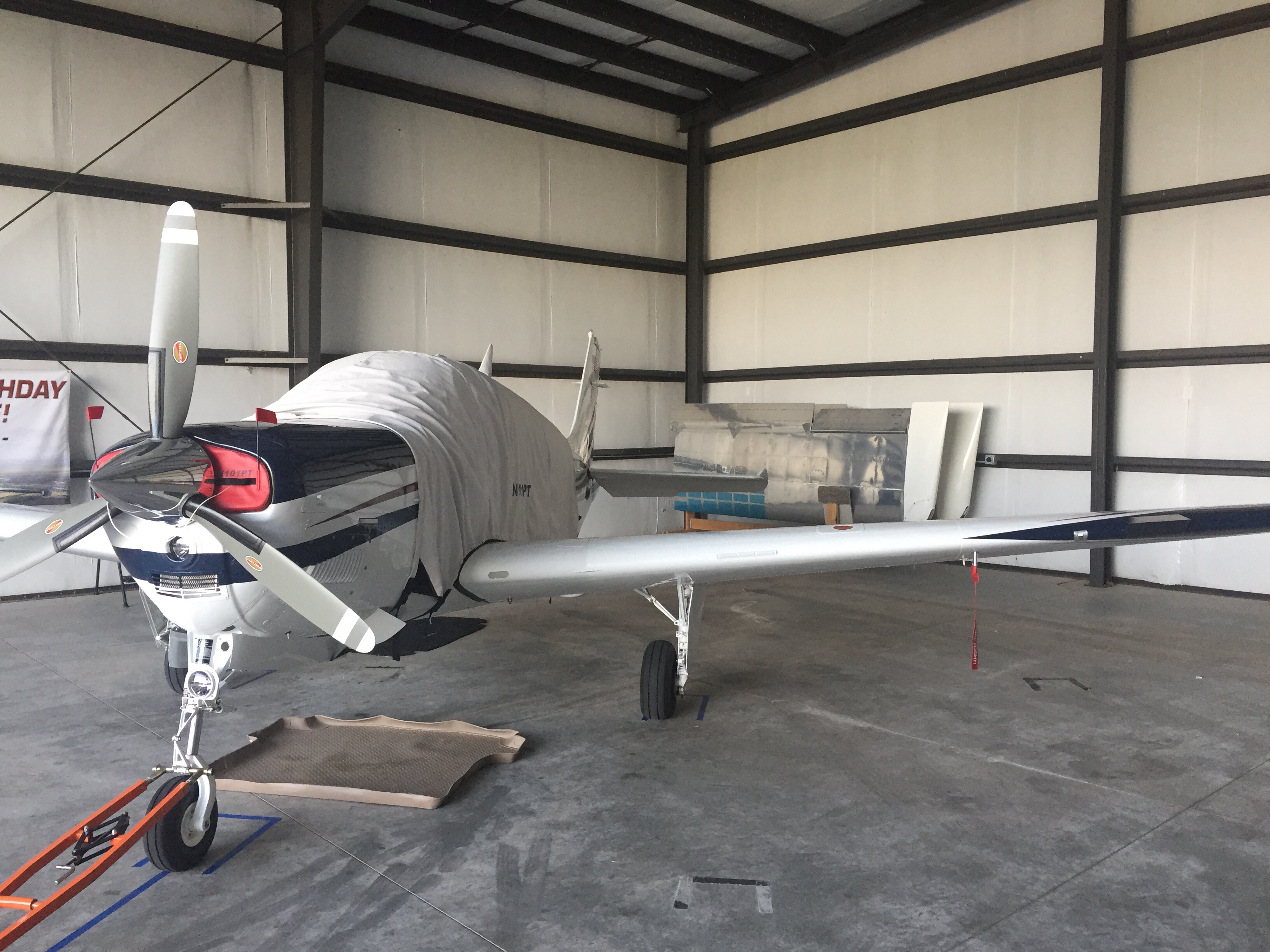
Since the wings are all complete, I need to get them out of the garage to make way for the finish kit and make me feel like I have real airplane parts in a hangar. My Diamond bros graciously offered a corner of their hangar for me to store the wings in until our hangar is available. So moving day came and anticlimactically went! It was like I designed the wing rack for the trailer and with Ron’s help, they rolled right on and off. We used a few tie downs and took our time on the 10 minute drive to the airport with no damage reported. I hope the fuselage move goes this smoothly!

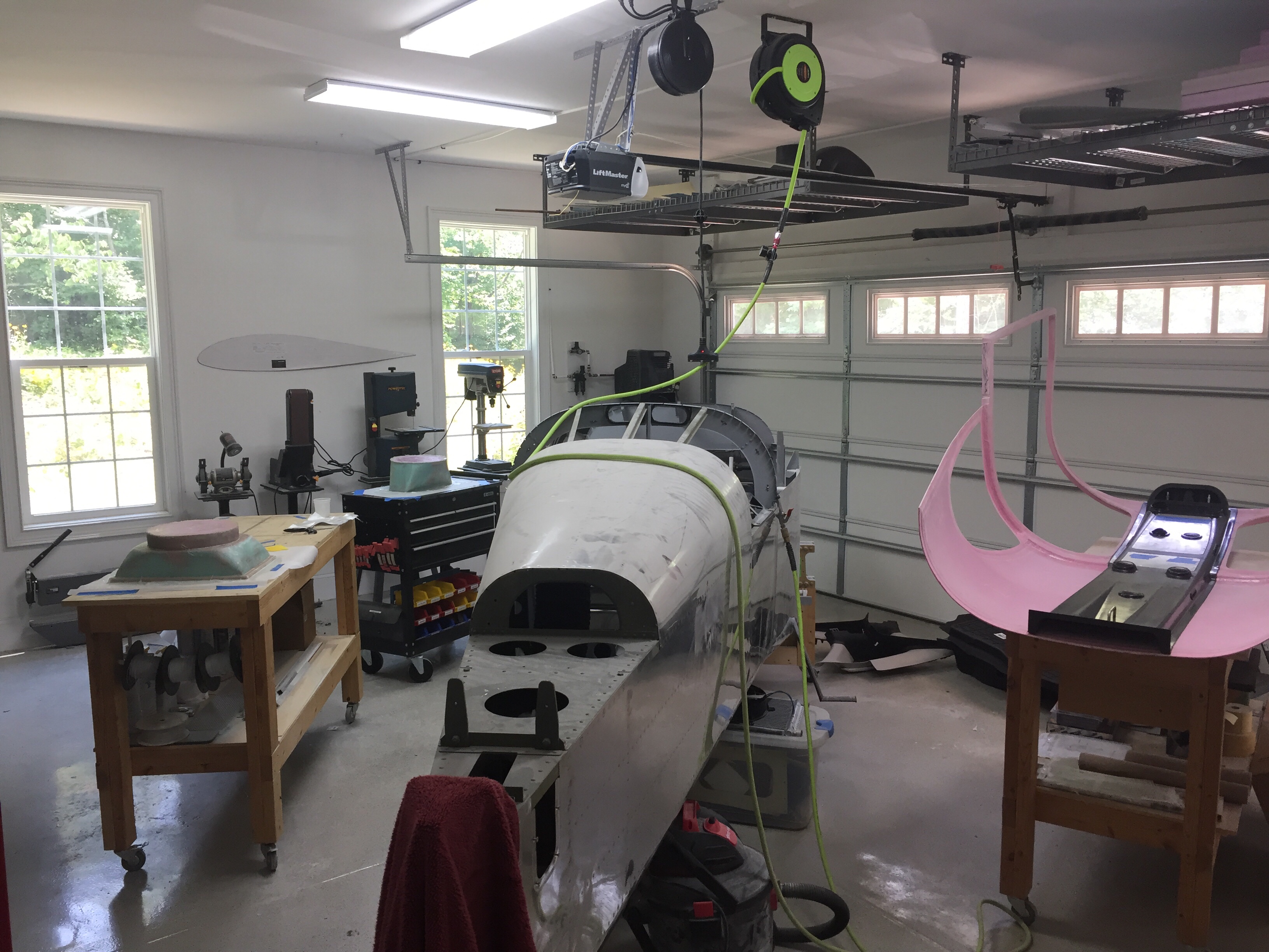
Bonnie the Bonanza is now babysitting RV wings. Meanwhile, back home the shop has so much room for activities such as finishing the cabin top and getting ready for the finish kit and cowling which are due to arrive early August.

Success hinges on the tips

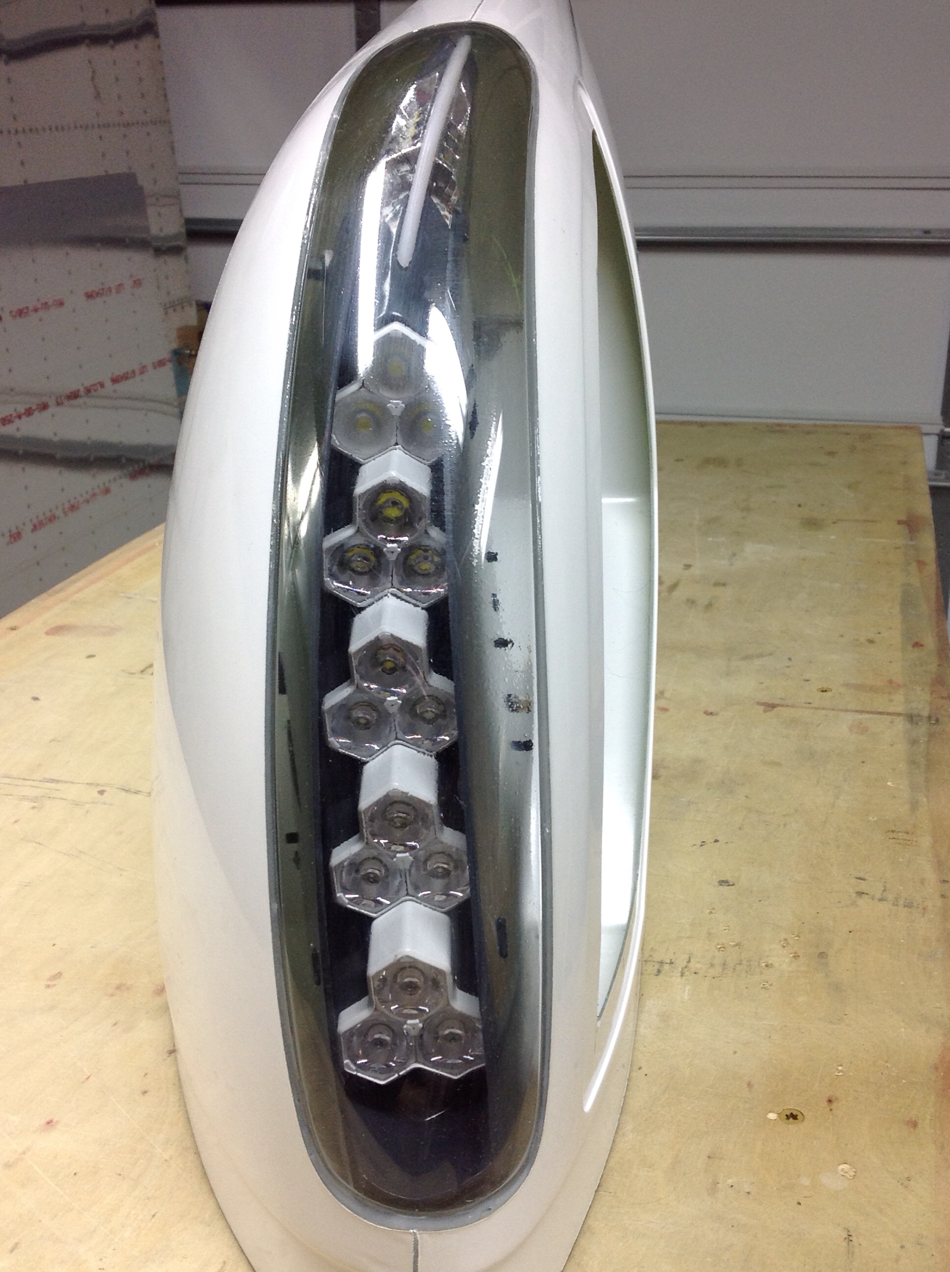
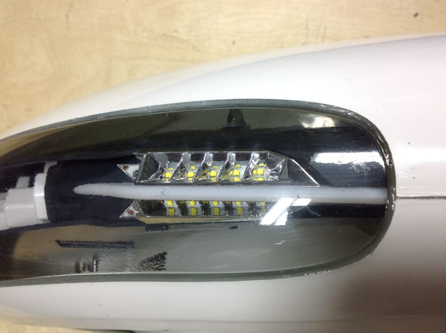
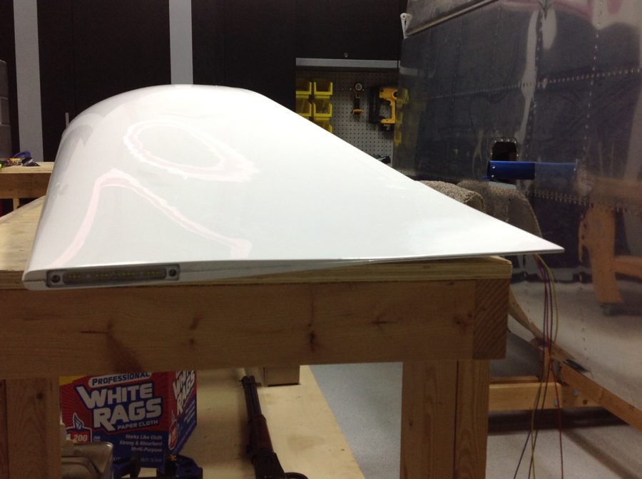
Some time ago, I received a large package from Aveo containing a brand new set of their ZipTips, wing tips with slick looking LED’s. I’ve been waiting on these things for years, ever since I saw them at Sun ‘N Fun in 2013. I’ve hounded poor Damien at Aveo relentlessly but it paid off with an opportunity to help them out with profile shaping and some prototype testing. In the end, I think it was worth the wait and I’m really looking forward to seeing these things all completed.

Now, because I was helping out, I received the prototype of the light modules and to say it nicely, they’ve been through a tough time. Unpacking the box, there were a few things rattling around and the back of the light module had come off.

First order of business was to test out the light modules. There is a 16 pin CPC with pigtails included, but the wires weren’t pinned out accurately causing me a few scares that I had shorted out the board or LEDs. After a few emails and testing, I was able to re-pin and document the proper wiring schematic. I did this for both sides and then took the time to re-seal the modules closed using some silicone and fresh hardware.

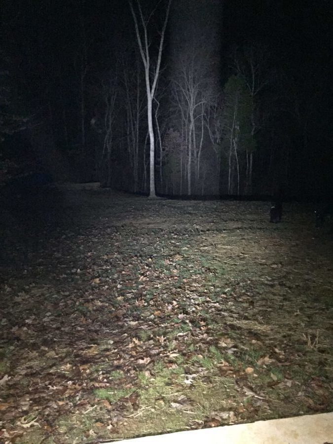
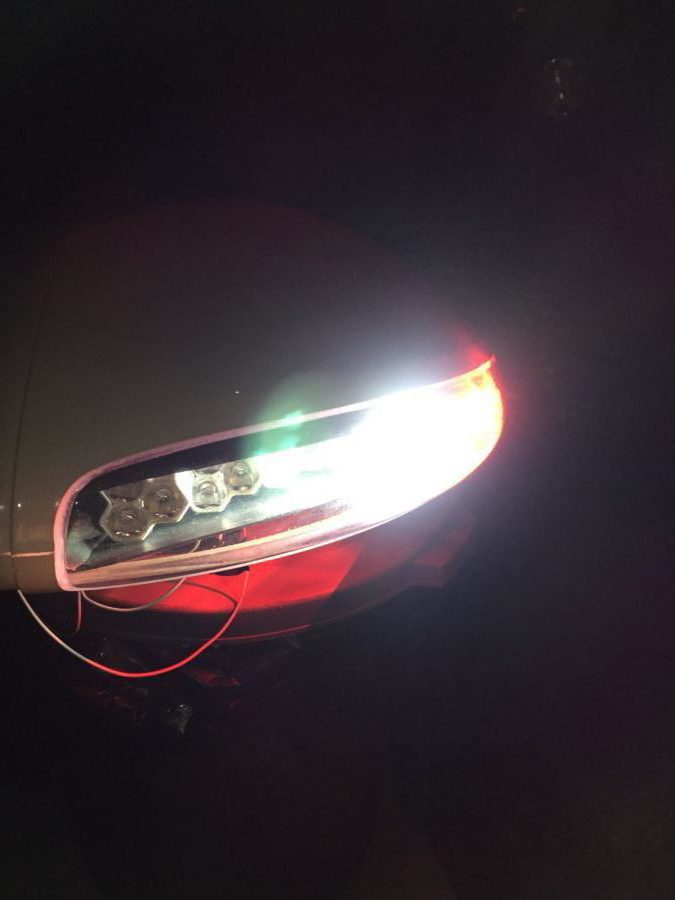
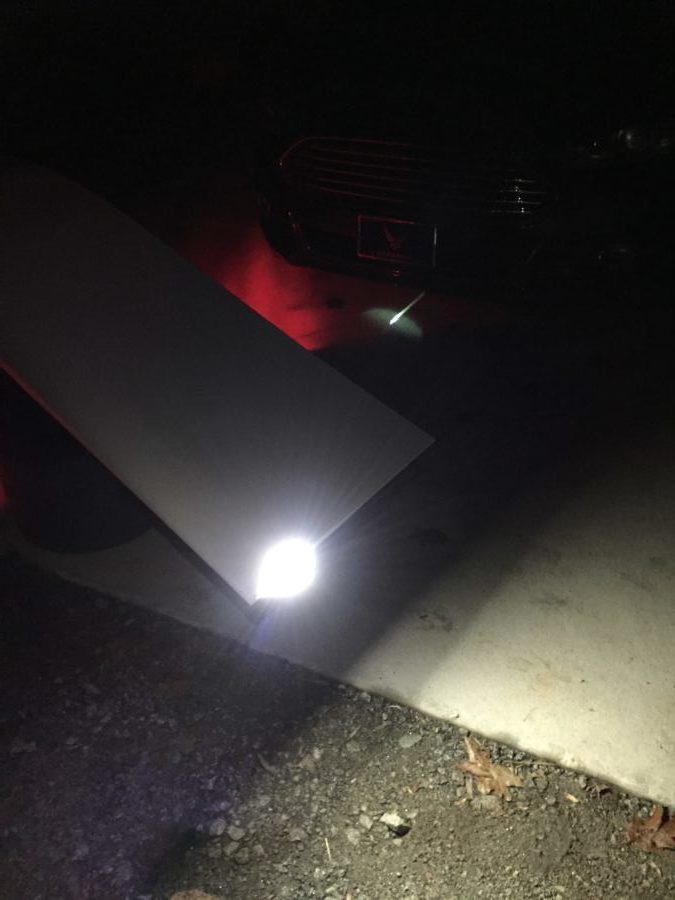
As others have said, these things are crazy bright! I hooked them up outside just to see what could be lit up and man, I am really impressed. Pictures and video don’t really do justice, but let’s say that I’ve flown many Pipers and Cessnas that have less than half of even one of these landing lights. Combined with the Aerosport taxi light, I think I’ll be able to light up the night just fine.

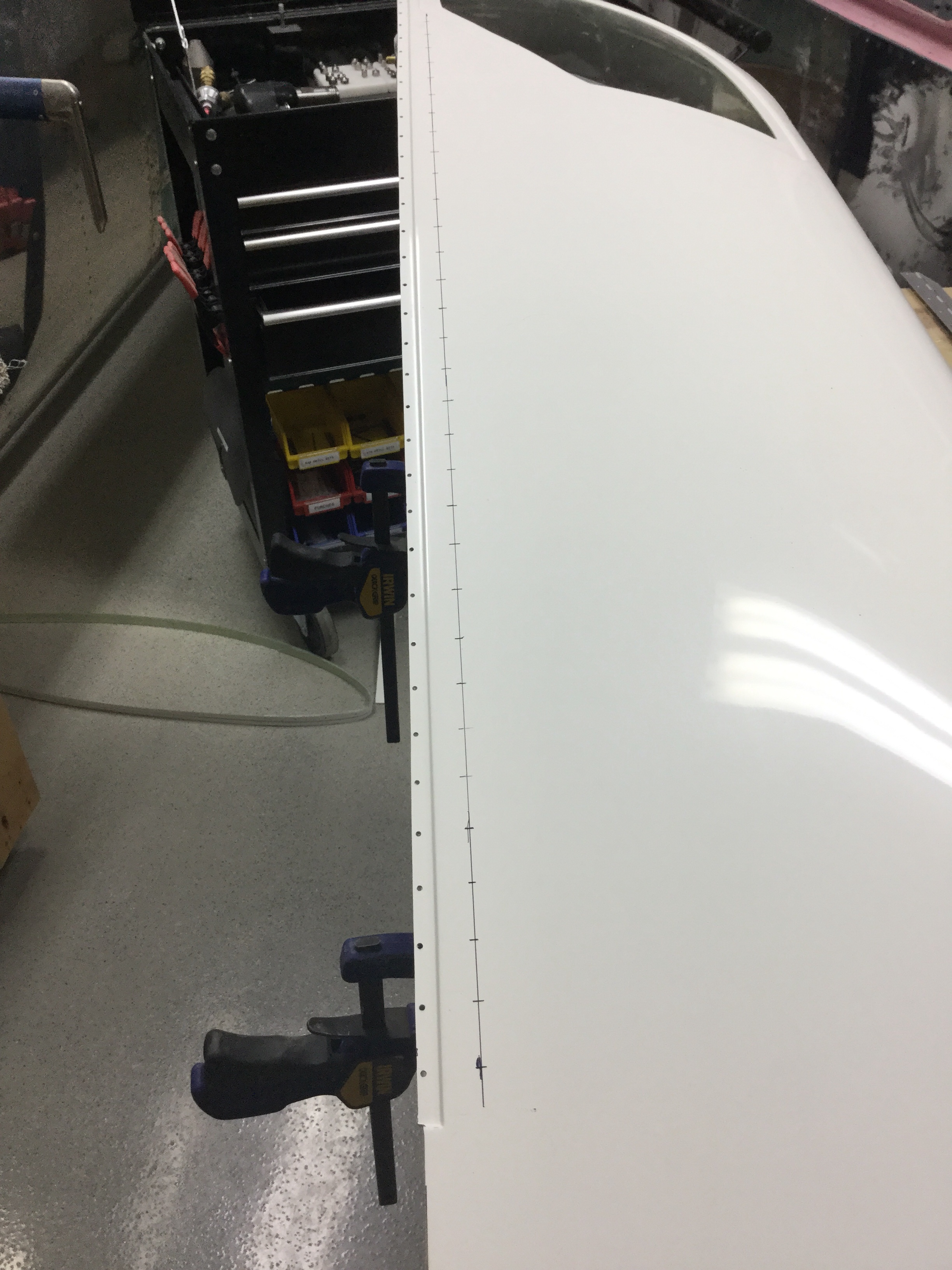
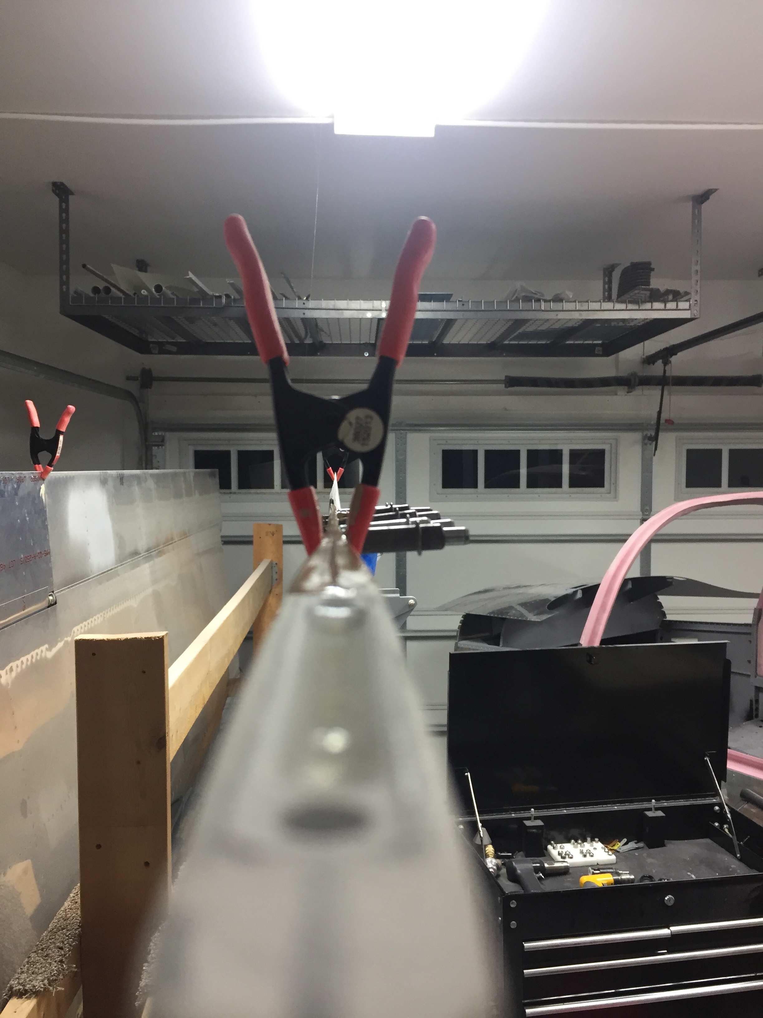
After testing, I started to do a rough fit and trim, but then they got put to the side waiting on the piano hinges that I planned to use to mount them. A year later, it’s time to finish them up so that I can call the wings complete. The first step was to complete the trim using the methods followed by others to install the tips with hidden piano hinges instead of screws and nut plates. I won’t go into detail as it’s documented on plenty of other build logs and forums out there such as VAF. Taking my time, I was able to get a really nice fit and used the cut off wheel on a die grinder just as I did with the cabin top.

I did run into some interference with the light module mounting hardware that butted up against the end rib. After talking to Van’s support, I drilled an accommodating hole in the rib to allow the hardware to protrude inward through the rib and let the tip sit flush against the skin. Once I had the hinges on, I split the trailing edge to reposition and line up with the ailerons. This is a common practice, even on the stock tips and was fairly straightforward. After a bit of work, I had a nice straight line from flap to tip.

Finally, I received some stainless steel hardware in for the light module access covers and mounted them with nutplates. Others have used a lot more fasteners than I did, and I’ll probably go back and add a few more before first flight. I painted the inside of the light area black to give the lights a meaner and cleaner look. I also painted the outside of the light reflectors, again, just for cosmetic purposes. Next up will be to run the wiring through the wings, mount the archer antenna, and make a pin retainer for the hinges.

Removing museum pieces

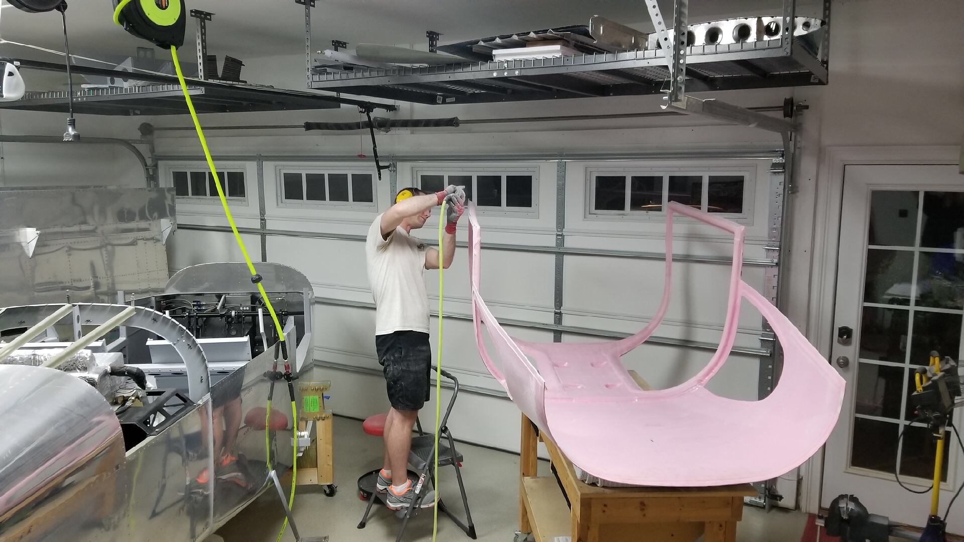
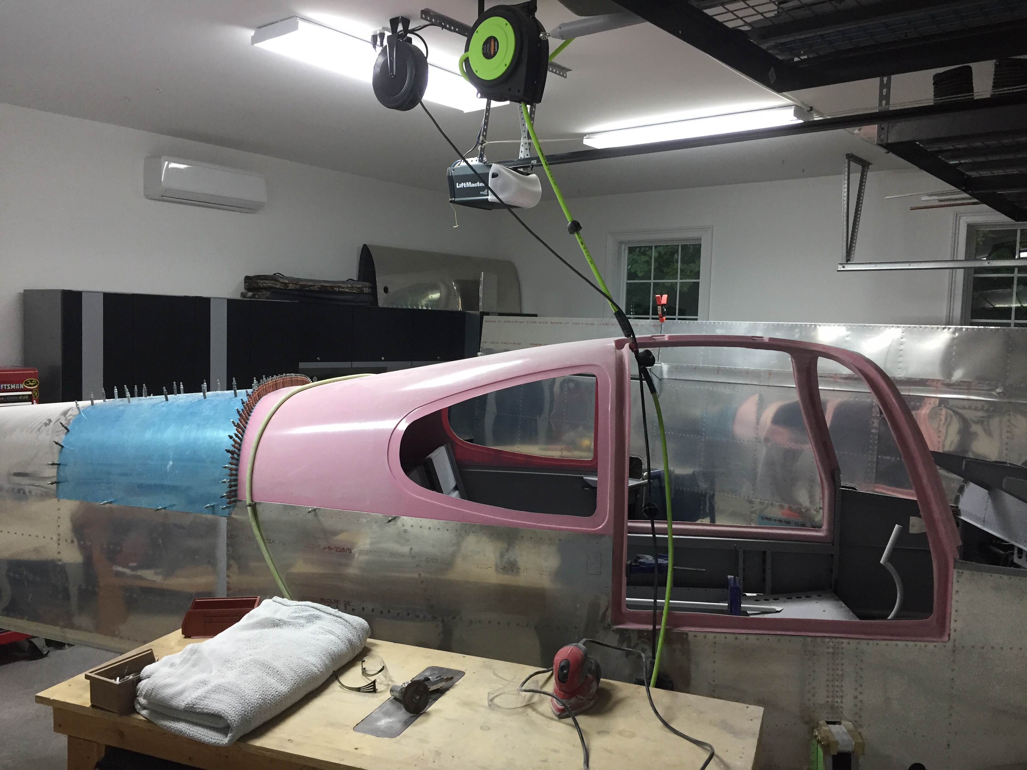
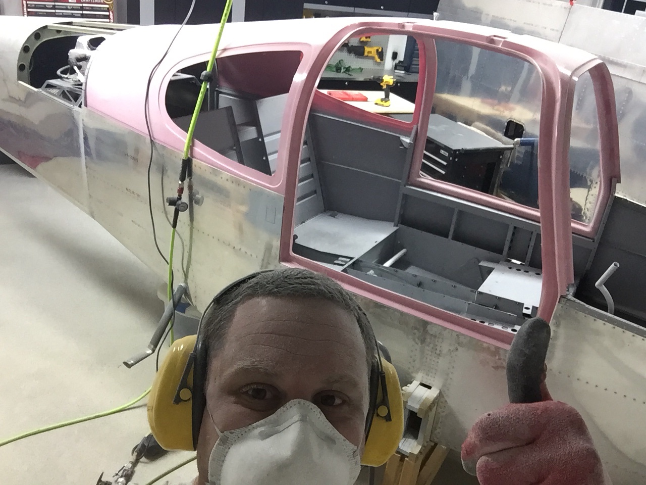
Parish came over for a pizza dinner with the wives and we managed to extract a museum piece off the ceiling.  The big pink thing that folks have asked about for the past three years is finally part of the airplane!  With his help, I did the initial trimming of the door frame and longeron area using the cut off wheel on the die grinder.  While it did produce some dust, we were outside and it really wasn’t a bad process. The scribe lines were pretty accurate where they were visible, but there were quite a few places the line was way off or missing all together.
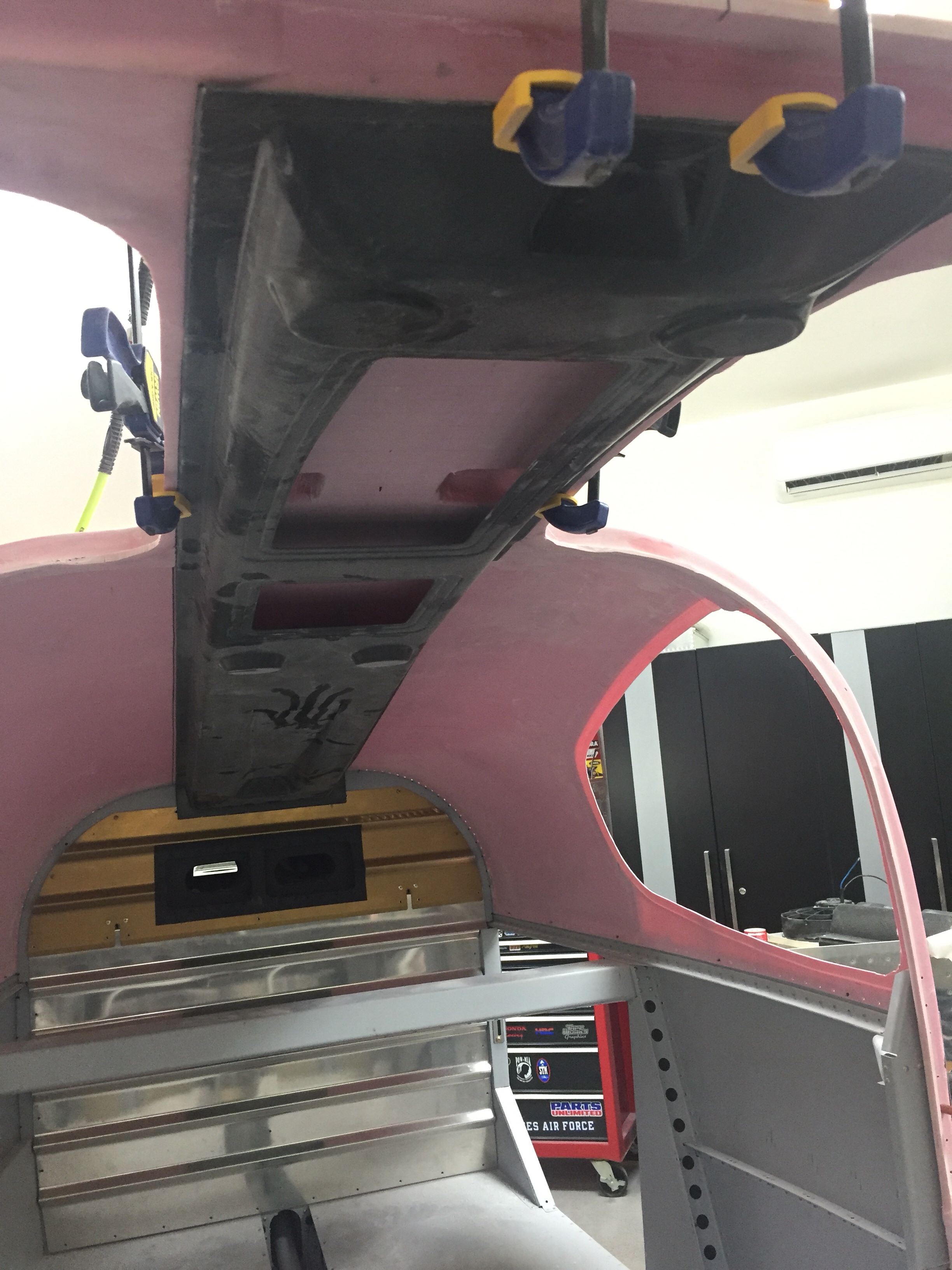
I initially trimmed the side skirts and door frame area just to get it on the fuselage. I had to take it on and off a few times and looking back, I wish I had thought out the process a bit better. You could measure the frame and make your own marks then do a final trimming. Fortunately, the top is mounted in a bed of flox so other than some sanding and contouring, it will be fine to have some gaps such as mine around the frame.

I had considered doing an overhead pulley system since I knew it’d come on and off, but really it’s not too heavy and I’ve found a good system of crawling inside and lifting the top up with my shoulders. Then I can put it on the seat rail and spar while I get out of the plane to lift it through the door frame onto the table. All in all I think I took it off about 10 times before it was all trimmed up.

It’s really cool to see all of this together. The thing actually looks more like a plane (or at least more of a plane) than it ever has. The back seats are really roomy! Next up is trimming the window openings, door flange, and windscreen flange.
Quit flapping around

One of the last projects before the cabin top section is the flap torque tubes and motor.  Switching gears back into progressively drilling holes in steel is a bit tough and time consuming.  Lots of oil, lots of shaving, and patience is needed.  I had to open up the holes with a deburr tool through the side panels which the tubes pass through.  All fairly straight forward, however, and everything lined up very well in the end.  The motor was an easy mount and at the end, I had to hook up a 9 volt battery to test it all out.  Pretty cool seeing systems start working in the airplane!

This was several evenings in the shop getting it all fabricated and I quickly realized that there is nothing left to do than put the cabin top on!  I also realized that while the cabin top is a massive amount of work, it’s also a good time to order the finish kit since having the doors is key to getting all the big work done on the fuselage.  I’m looking forward to getting the big pink thing down from the ceiling and on the fuselage!