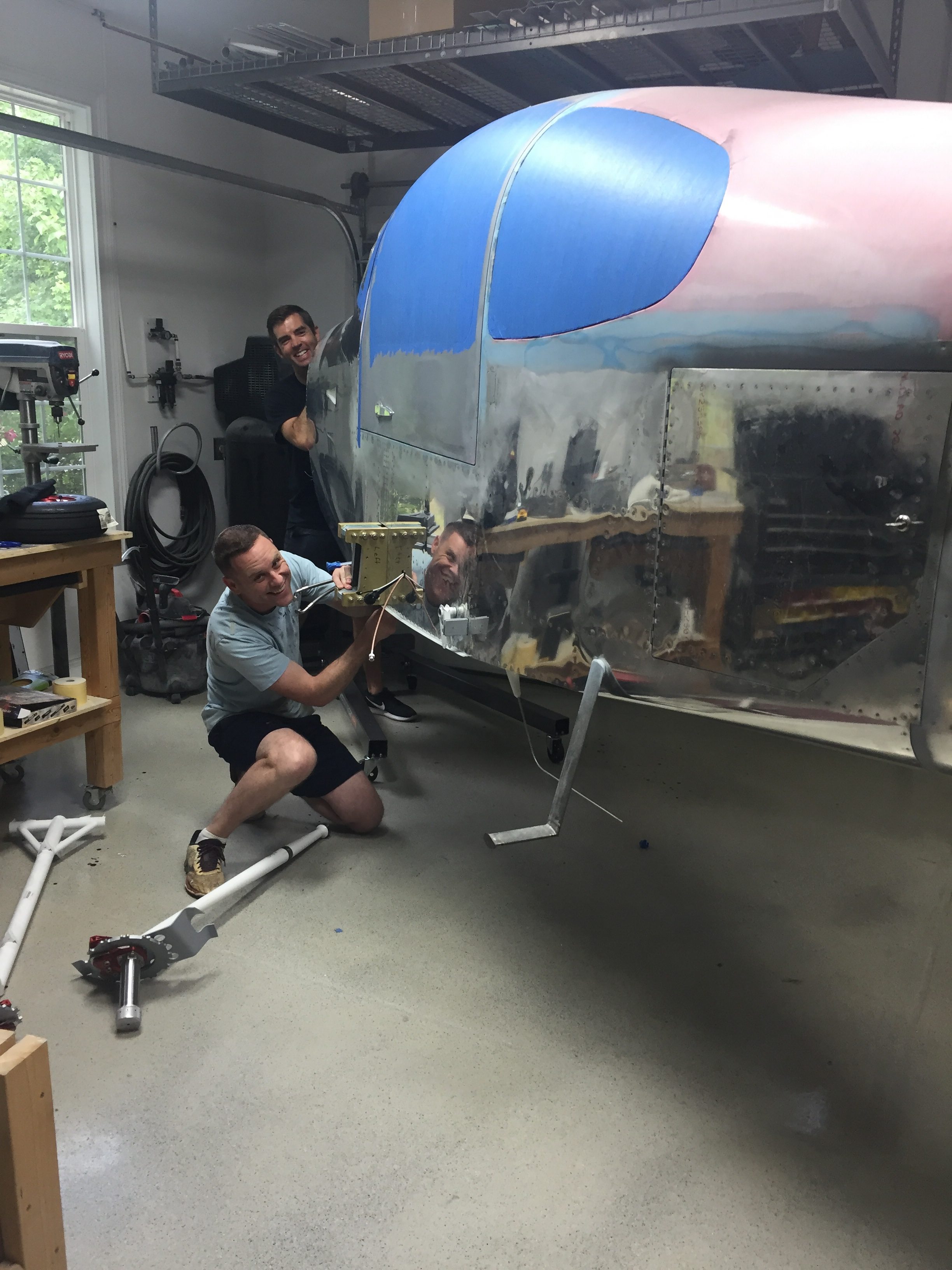
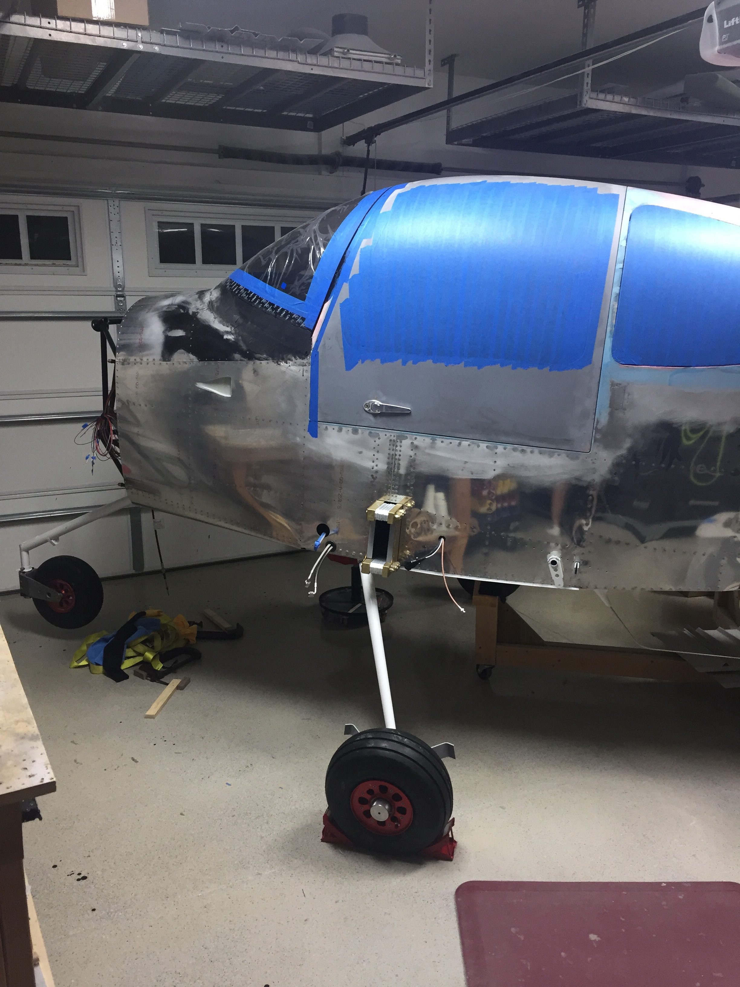
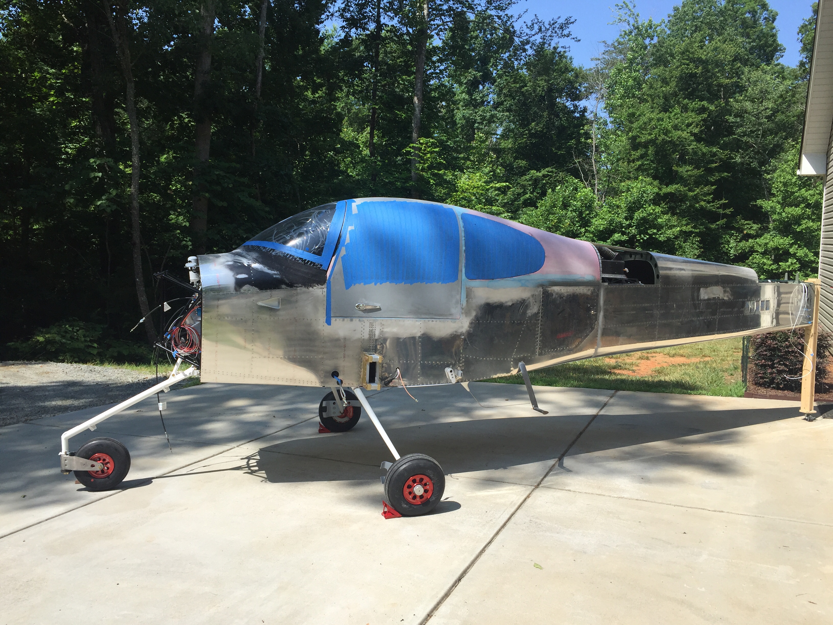
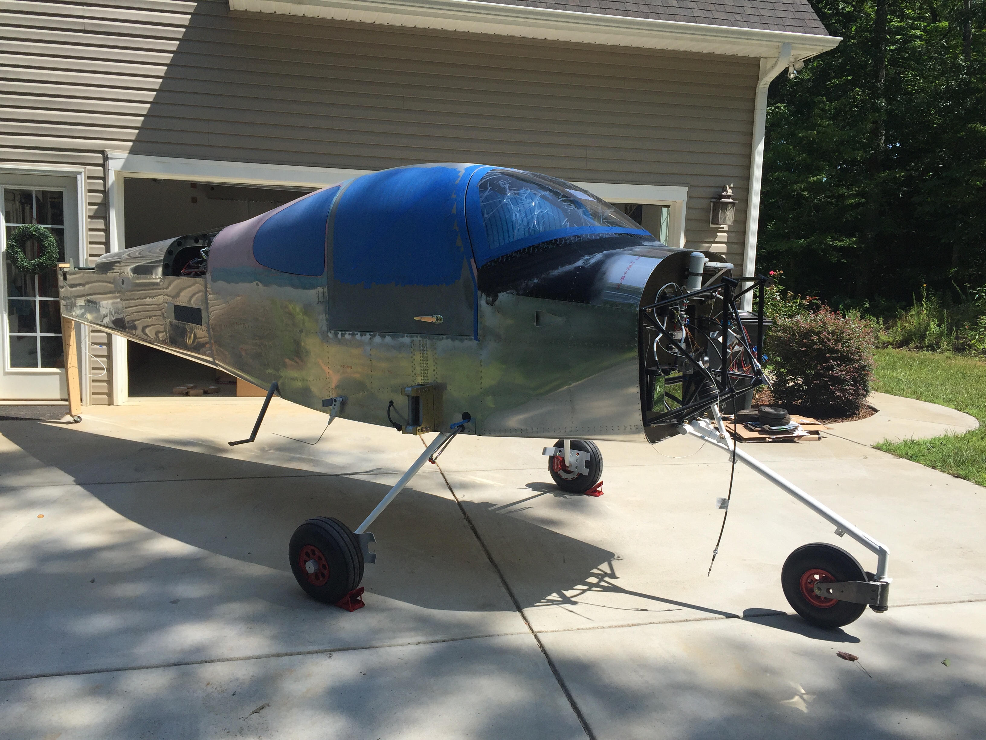
Hate to say it, but you’ve gained weight

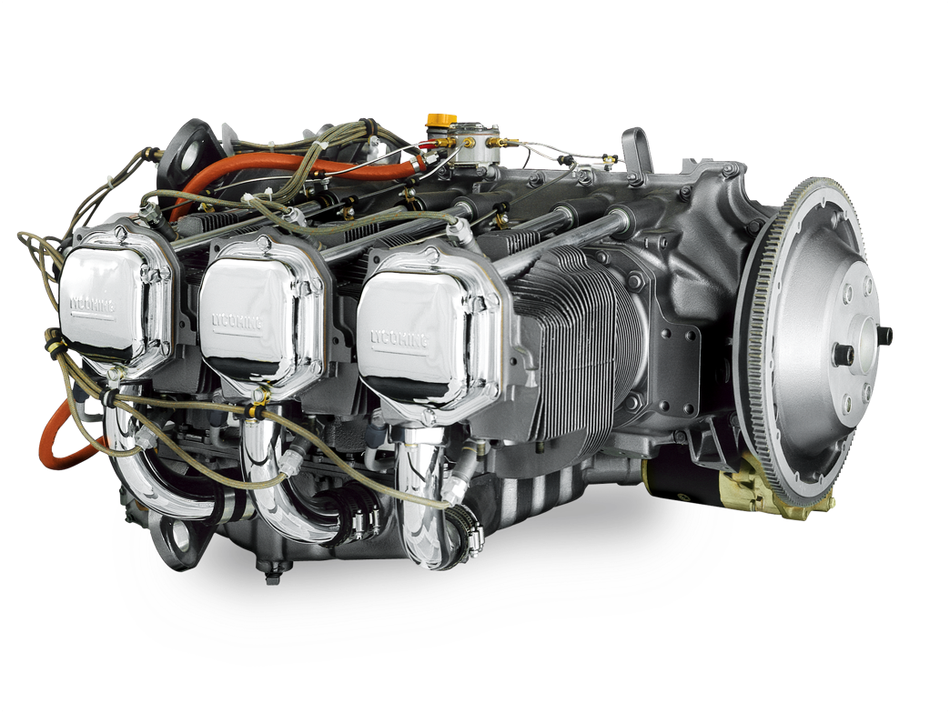
About 375 pounds to be exact, all on your front end!
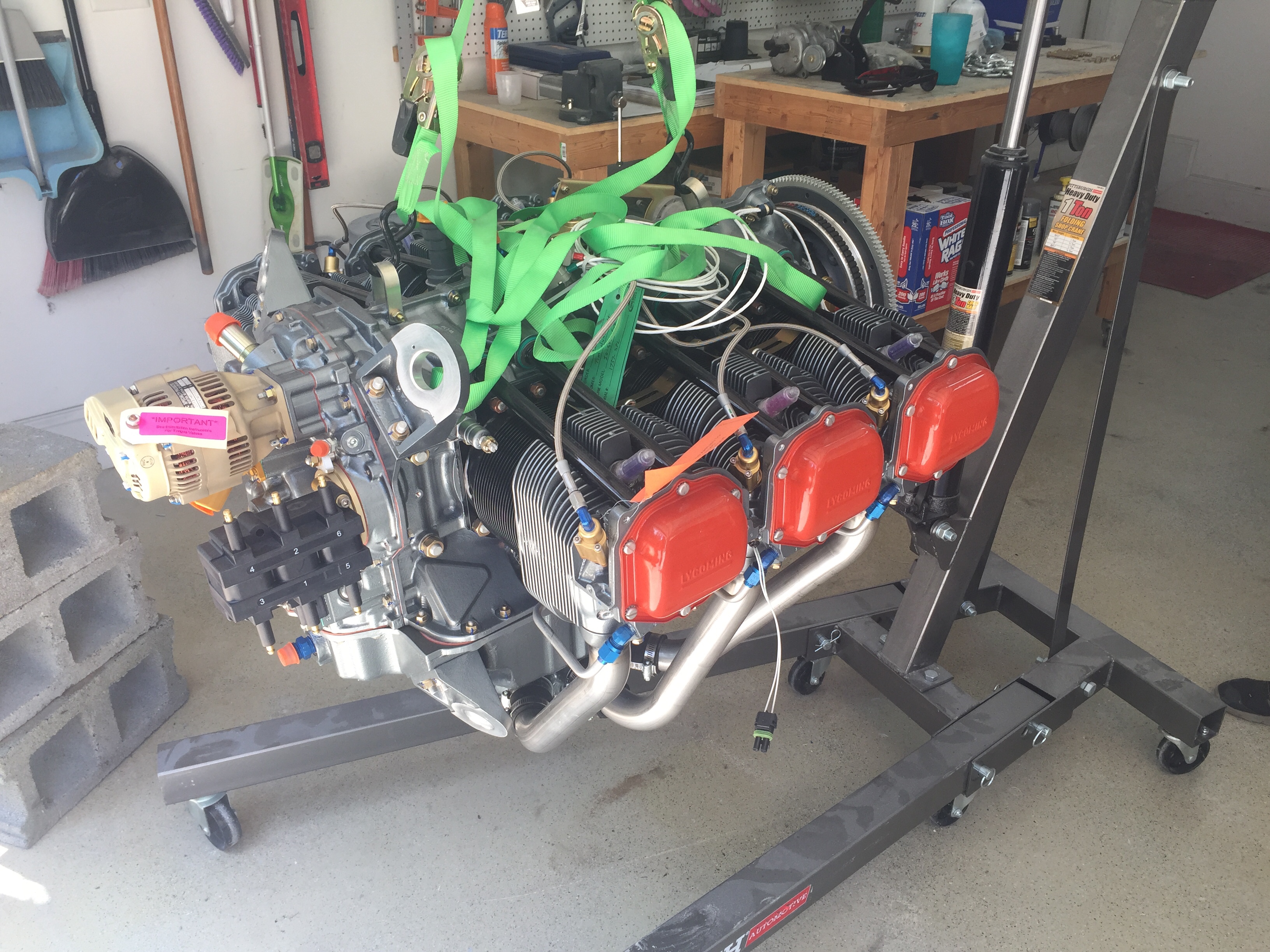
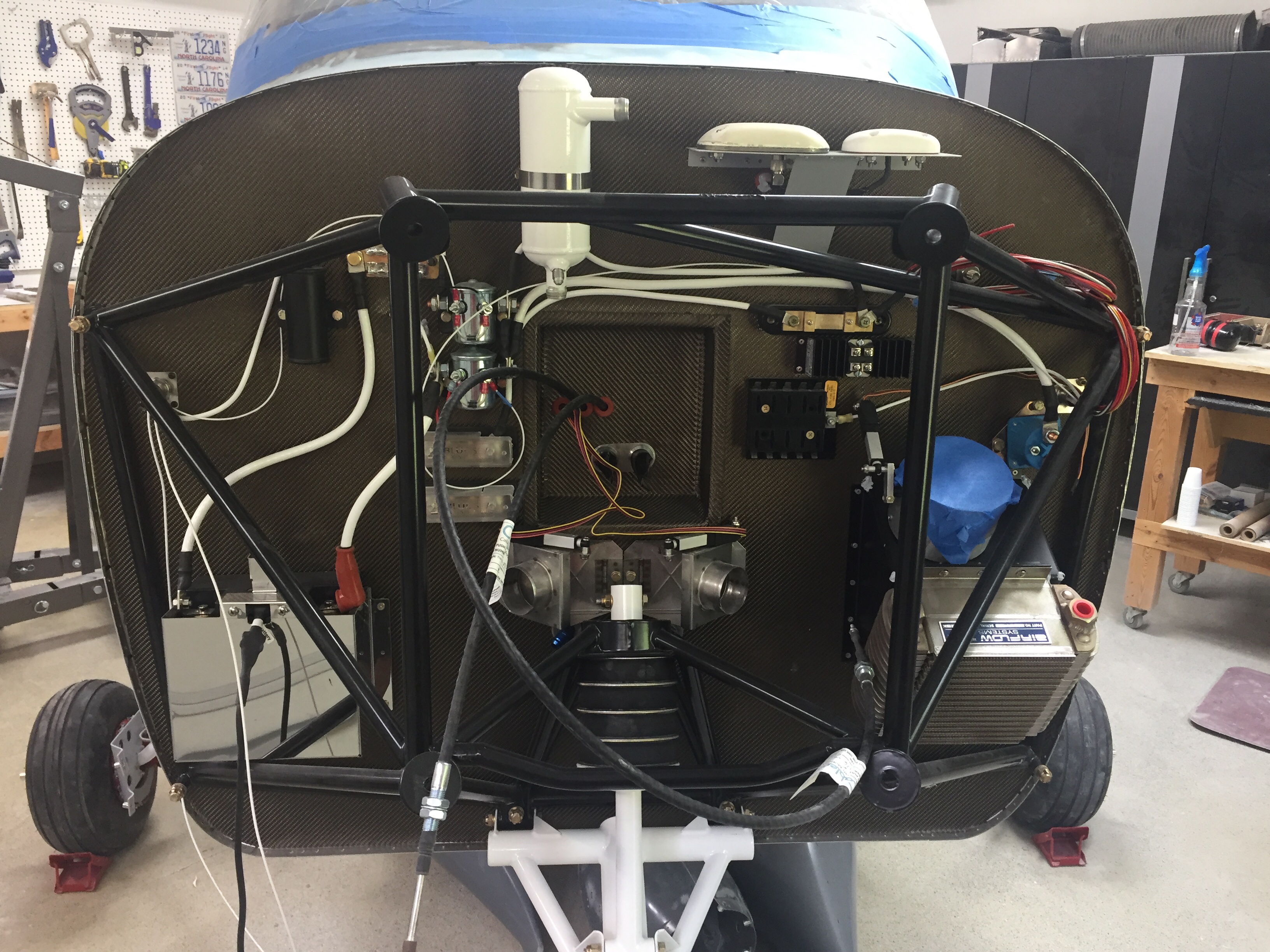
I enlisted the help of friend/flier/builder/neighbor Dan Olsen to help me hang this piece of art on the front end.  I had done a little prep work such as sealing a few penetrations in the firewall that would be tough to get to and removed the air oil separator, as I was pretty sure my original location would interfere with the back up alternator.
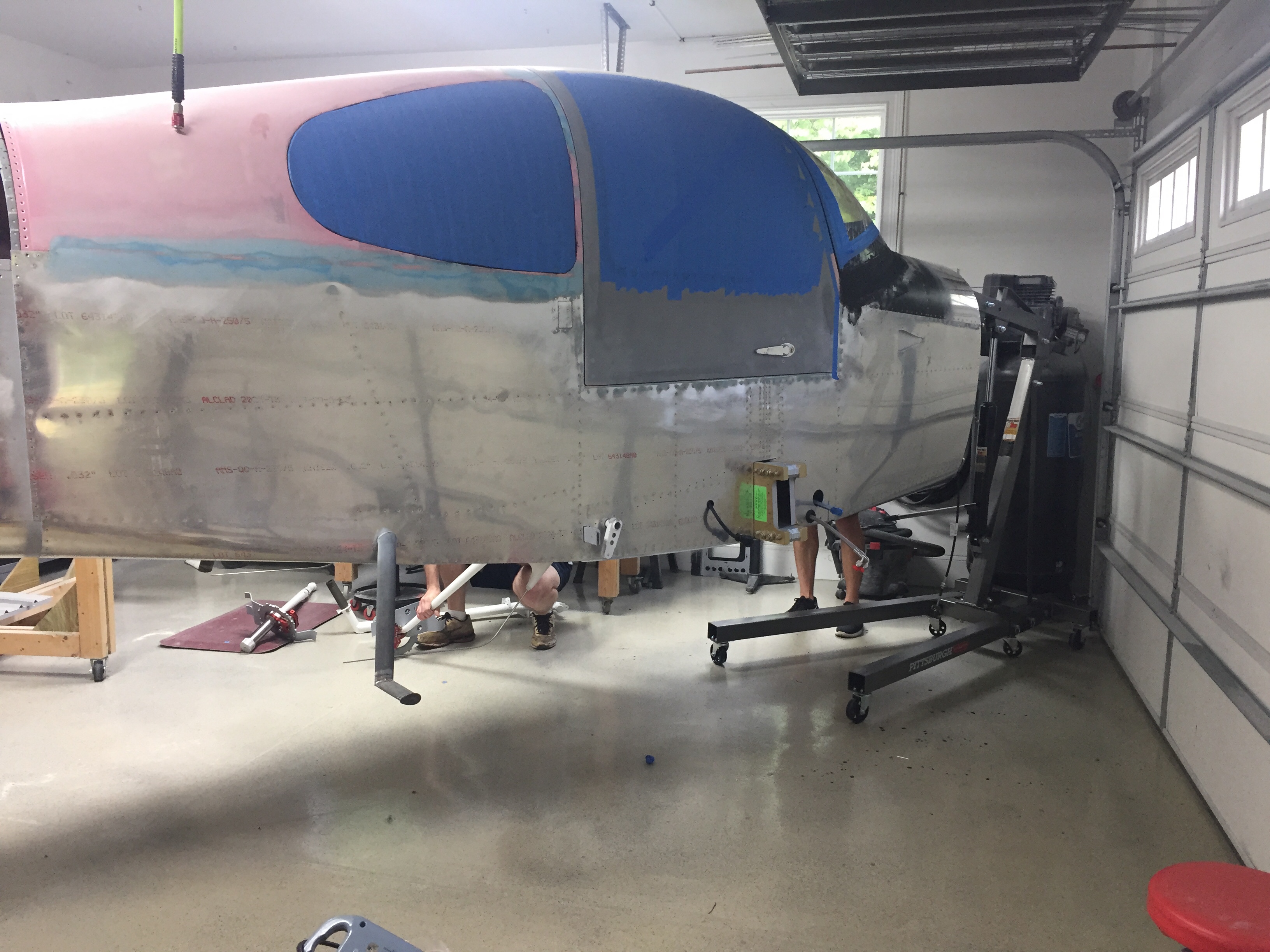
Some folks have had a lot of headache while hanging the engine while others have thrown it right on.  Overall, I’d say we were towards the later, as the engine behaved admirably and didn’t give us too much trouble.  We supported the tail of the fuselage to put the nose gear on the ground and used ratchet straps on the engine hoist so we could adjust the angle of the engine relative to the engine mount.
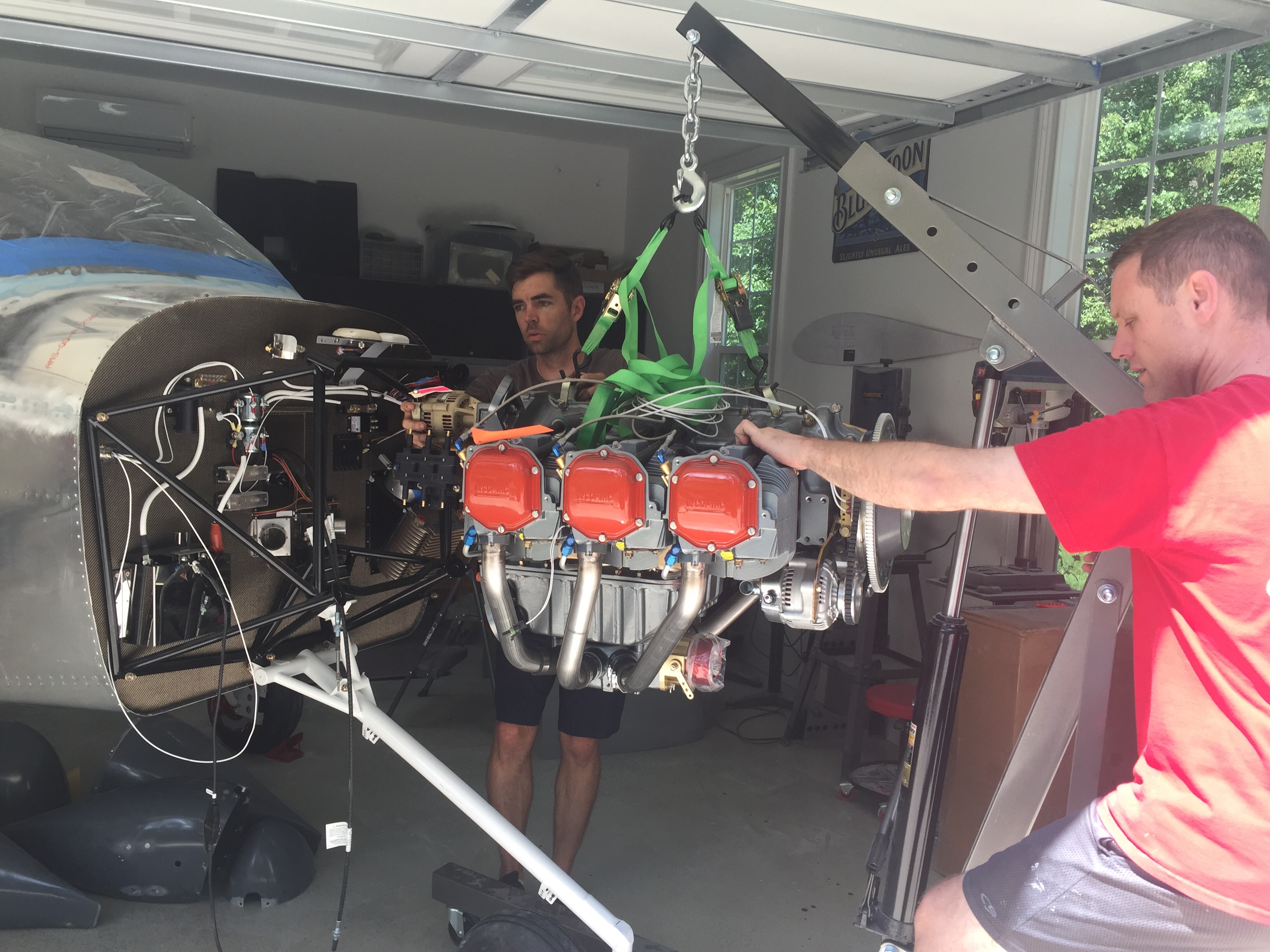
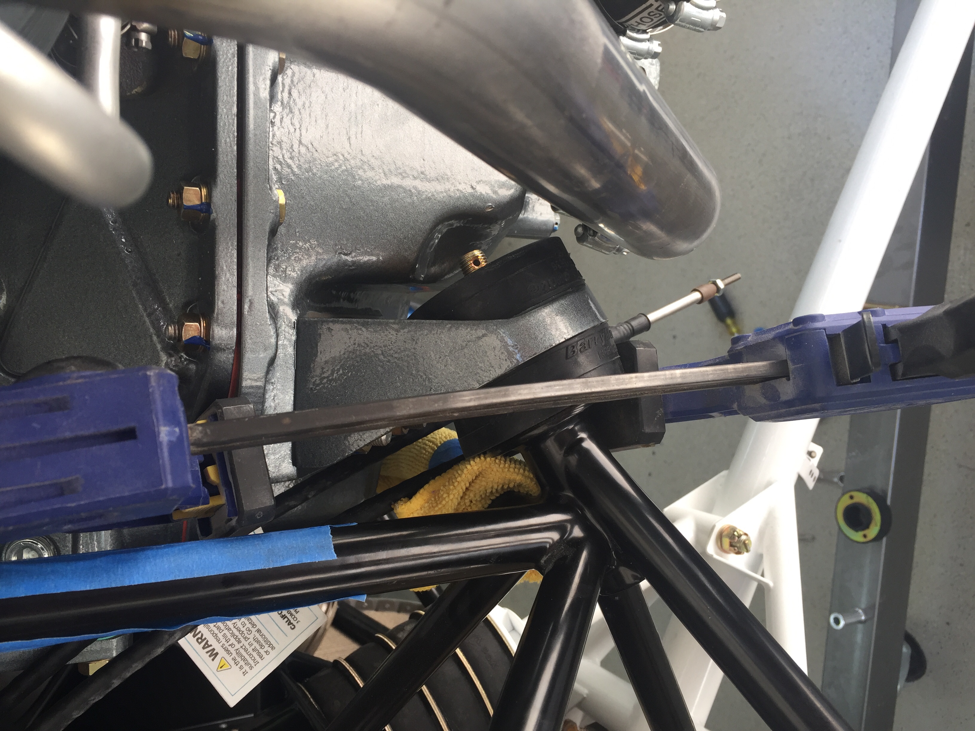
The top mounts went on easy, of course, and we secured the hardware enough to hold it in place.  The lower bolts were the more difficult ones, as with the dynafocal mount, the engine needs to be nested in the mount but gravity is working against you.  We found that using a easy grip clamp helped hold and compress the mounting pads enough that the bolts were able to be tapped in without much force.  It all sounds simple and easy but was 30 minutes of tough work and a lot of maneuvering tools.
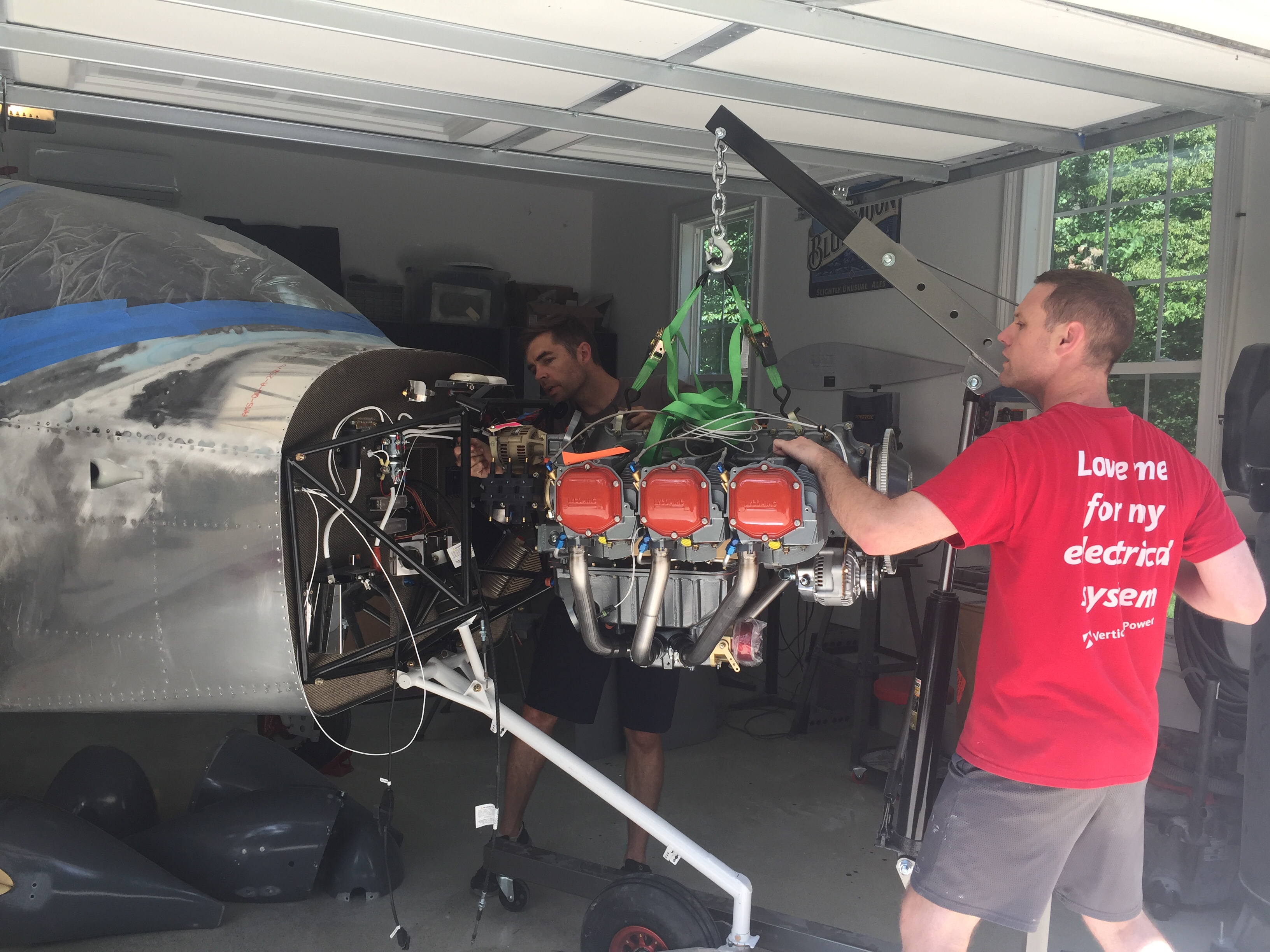
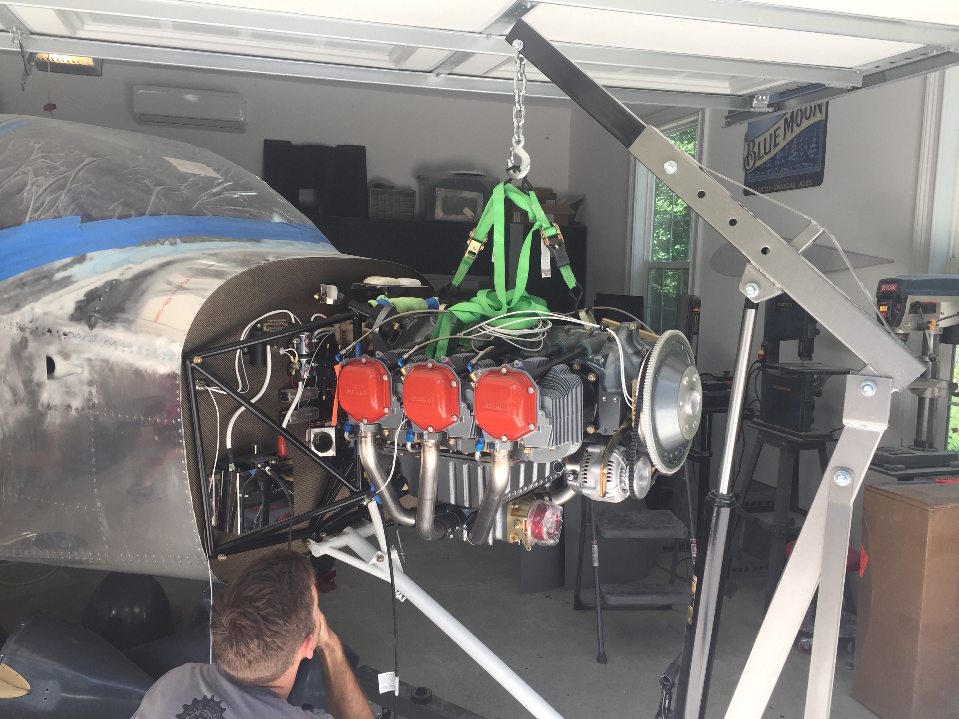
Four bolts in and we have an engine!  Remarkable that all of the force, torque, and stress is secured with four bolts.  The mount modification by Barret was perfect for the cold air induction and it’s nice to have the fuselage balanced nose heavy now so no more tail stand required!  She is officially a tricycle aircraft now, not a four wheeler.
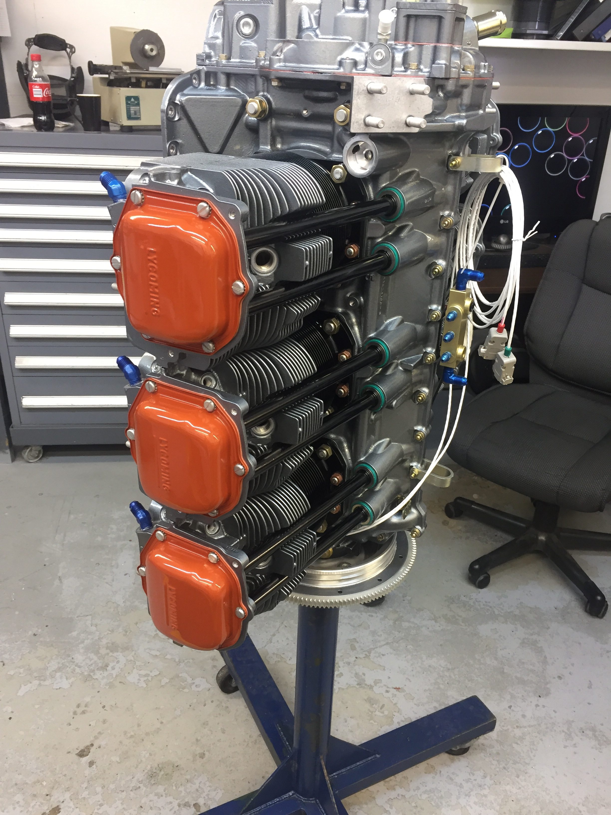
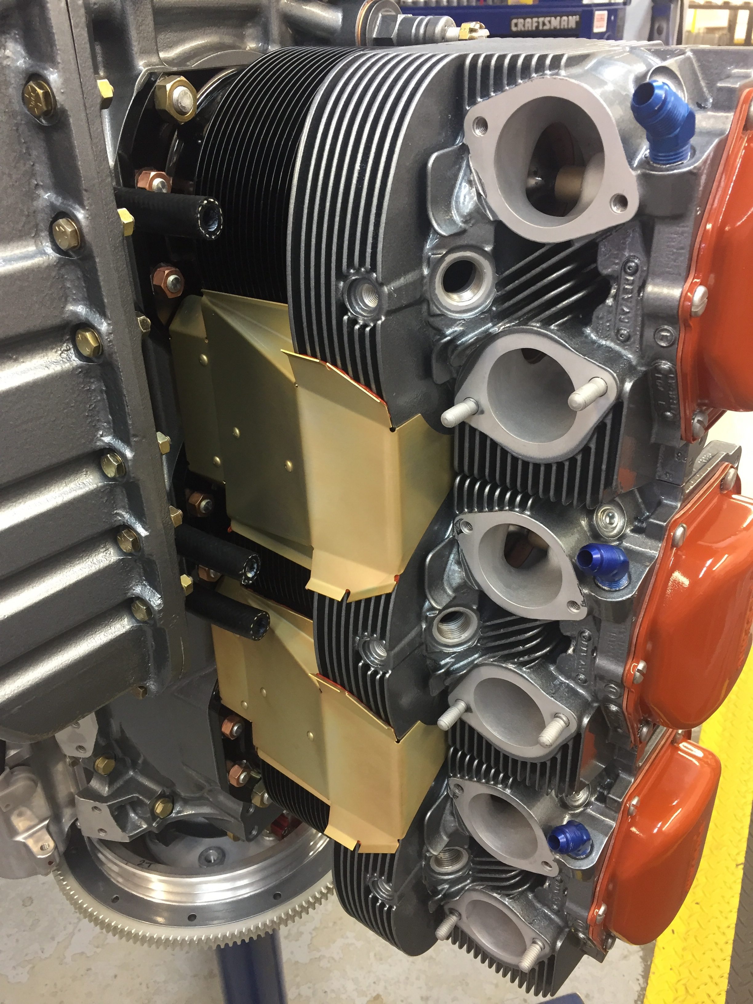
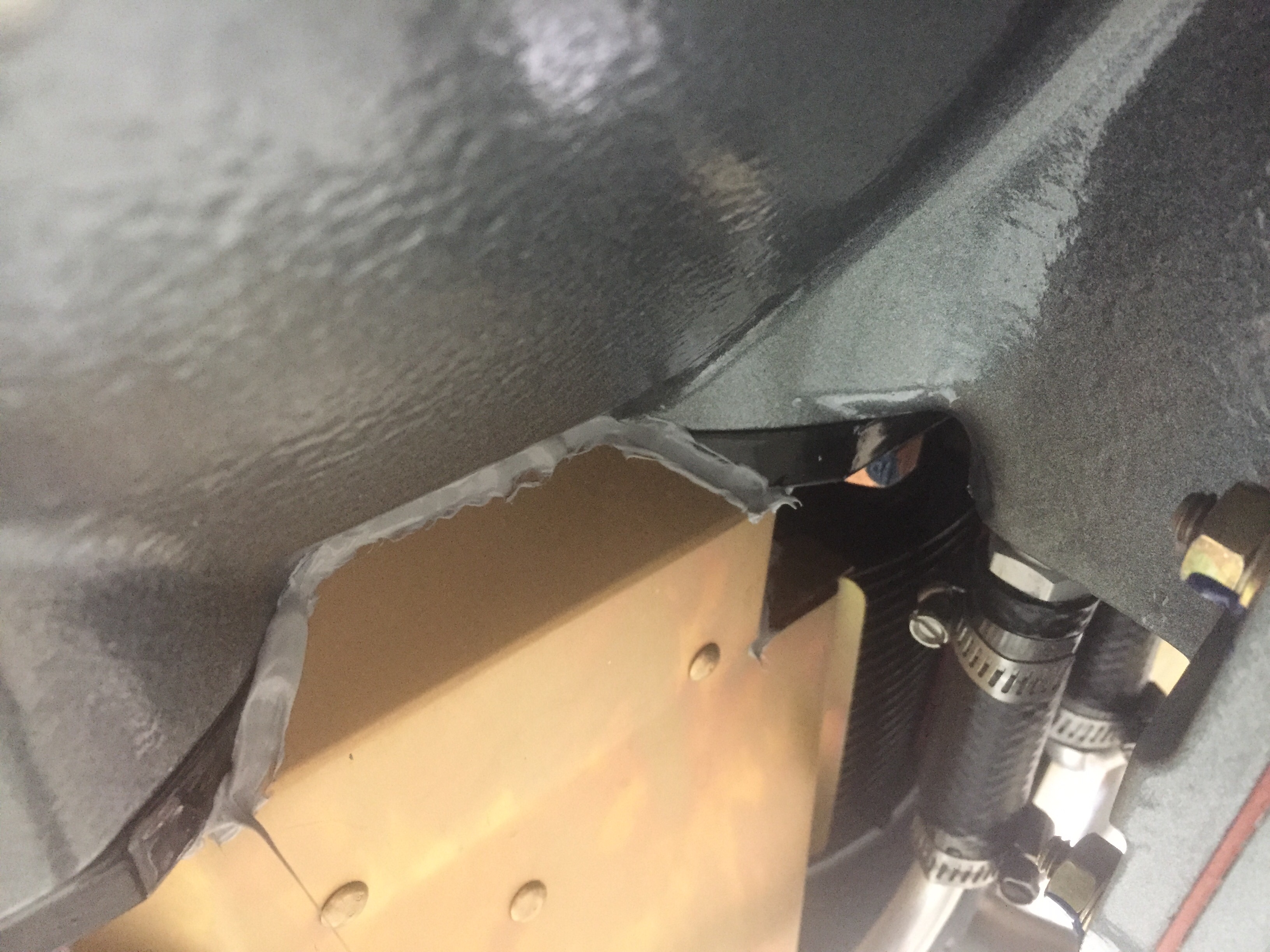
I took some extra time and used my sealant gun to really seal up the factory intercylinder baffles well.  I’ve researched and discovered this is critical to keeping cooling air traveling through the intended paths and fins which helps control CHTs in flight.  Doing it now before accessories and exhaust are mounted makes the task doable and the sealant gun with curved nozzles makes it easy.  It was actually really fun finding all the little spots to seal up and visualize where are can escape from the cooling envelope.  It also makes a lot of sense how you can not get great cooling from a stock engine and baffle setup without some extra TLC such as this.
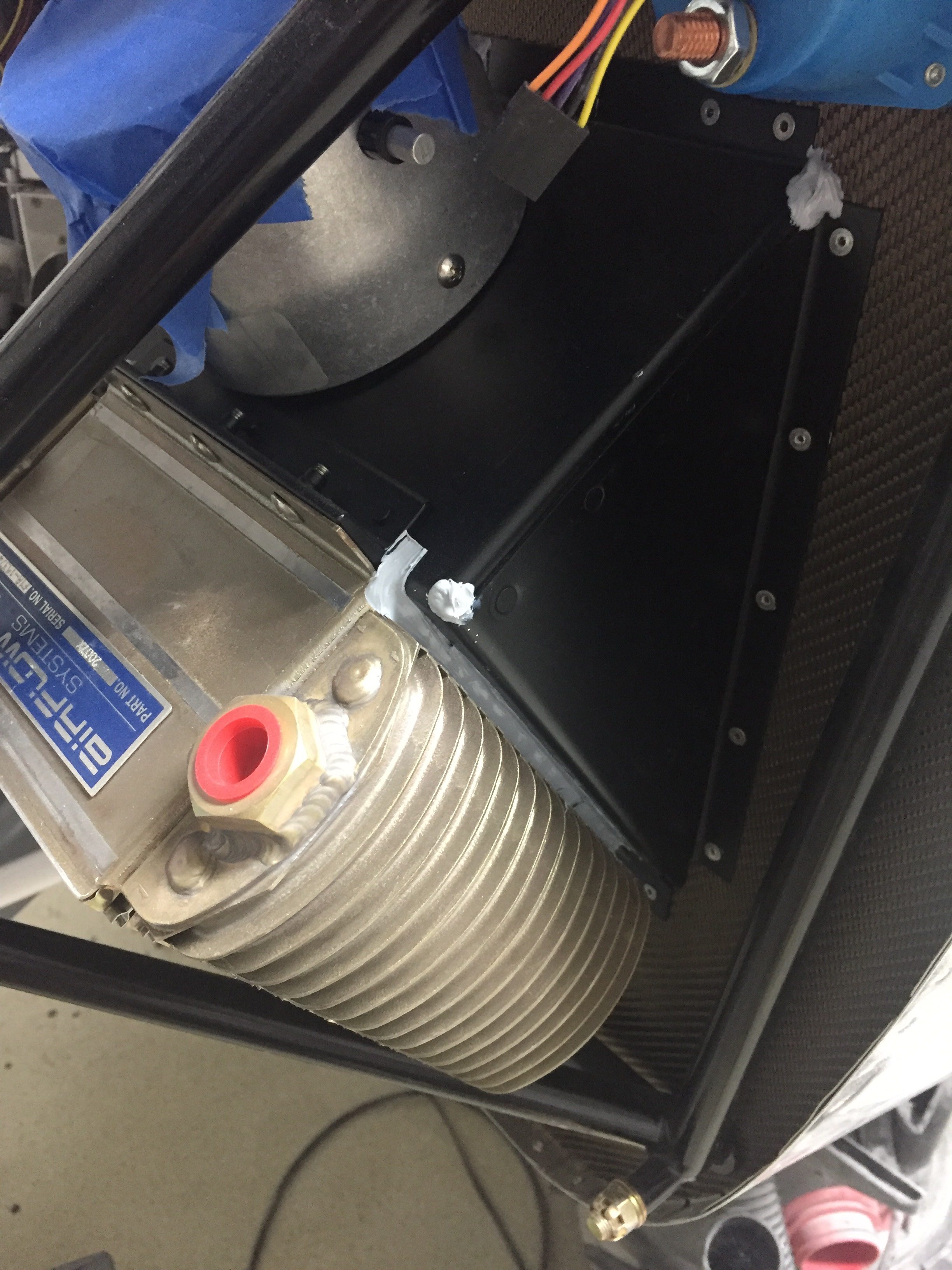
The oil cooler was also installed and sealed carefully to maximize air efficiency through the cooler.  This is the next size up from the stock cooler and the modified mount works great without a lot of fuss.  I’m sure it could be better if I had mounted it paralell to the ground and had a nice clean duct, but folks are flying a lot with great results just as I am doing it.  The butterfly valve should help keep the oil temps higher in cold/high altitude flights that we have planned.
Baffles are up next and can be a bit of a tricky project to get completed.  There is also a well documented modification on number 6 cylinder that I’ll do to increase cooling and help reduce CHTs on that notoriously hot cylinder.  The baffle on number 5 is the hardest to fit onto the engine, so I taped up about everything to avoid or at least minimizing messing up the goregous paint job on the engine.  There are a lot of unique pieces of metal and I am awed at who ever designed the presses to stamp these things out.
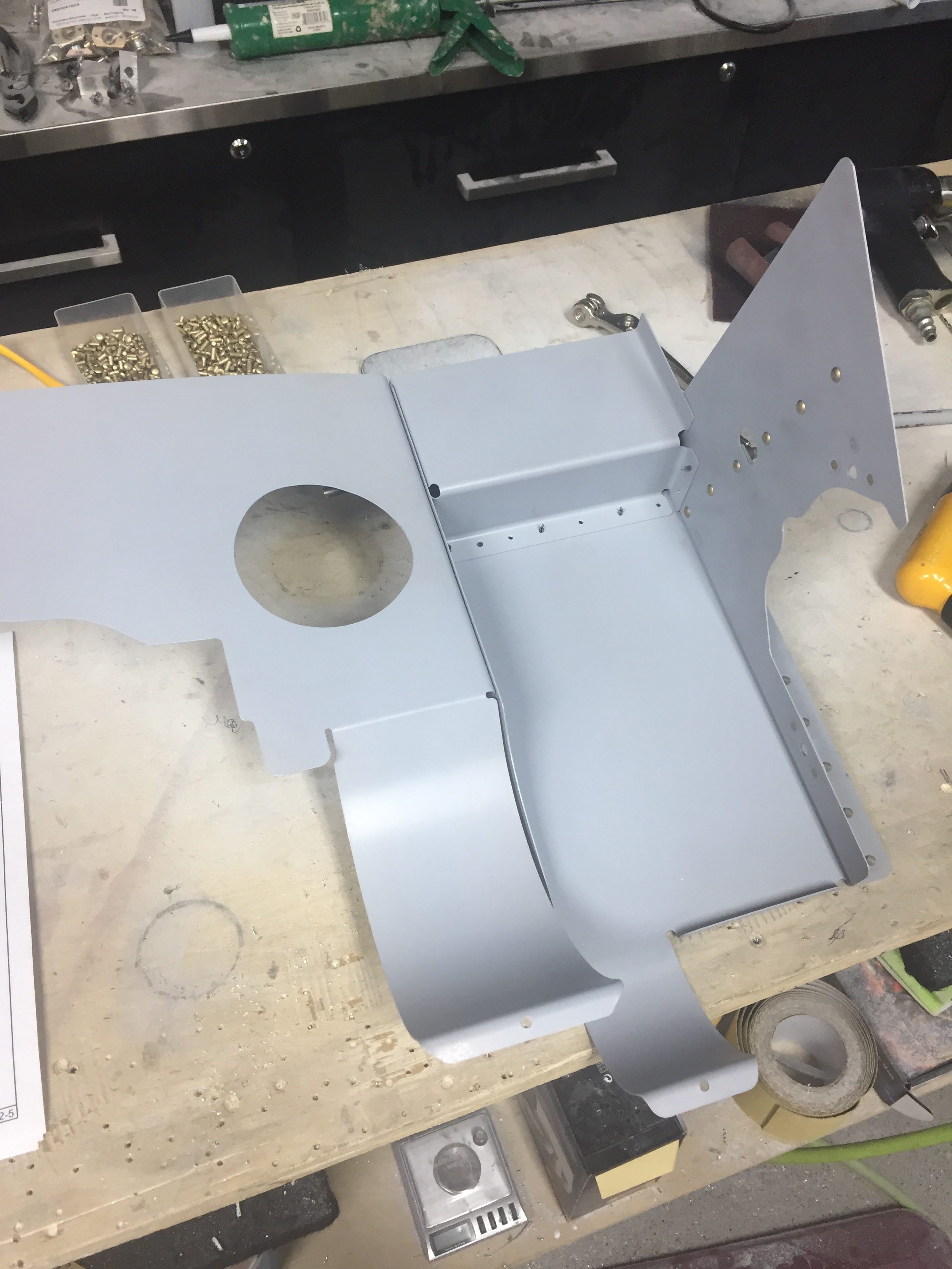
Behind number 6, the fins are not deep enough to allow air to channel between the cylinder wall and the baffle.  Some have put a washer here which just pushed the baffle out a bit and allows some air to go through.  The RV-14 has a new mod where a channel is built in which provides clearance in that area, so I made the same modification to mine.  A few mockups using manilla folders, and I finalized a design which I riveted on and will seal once painted.
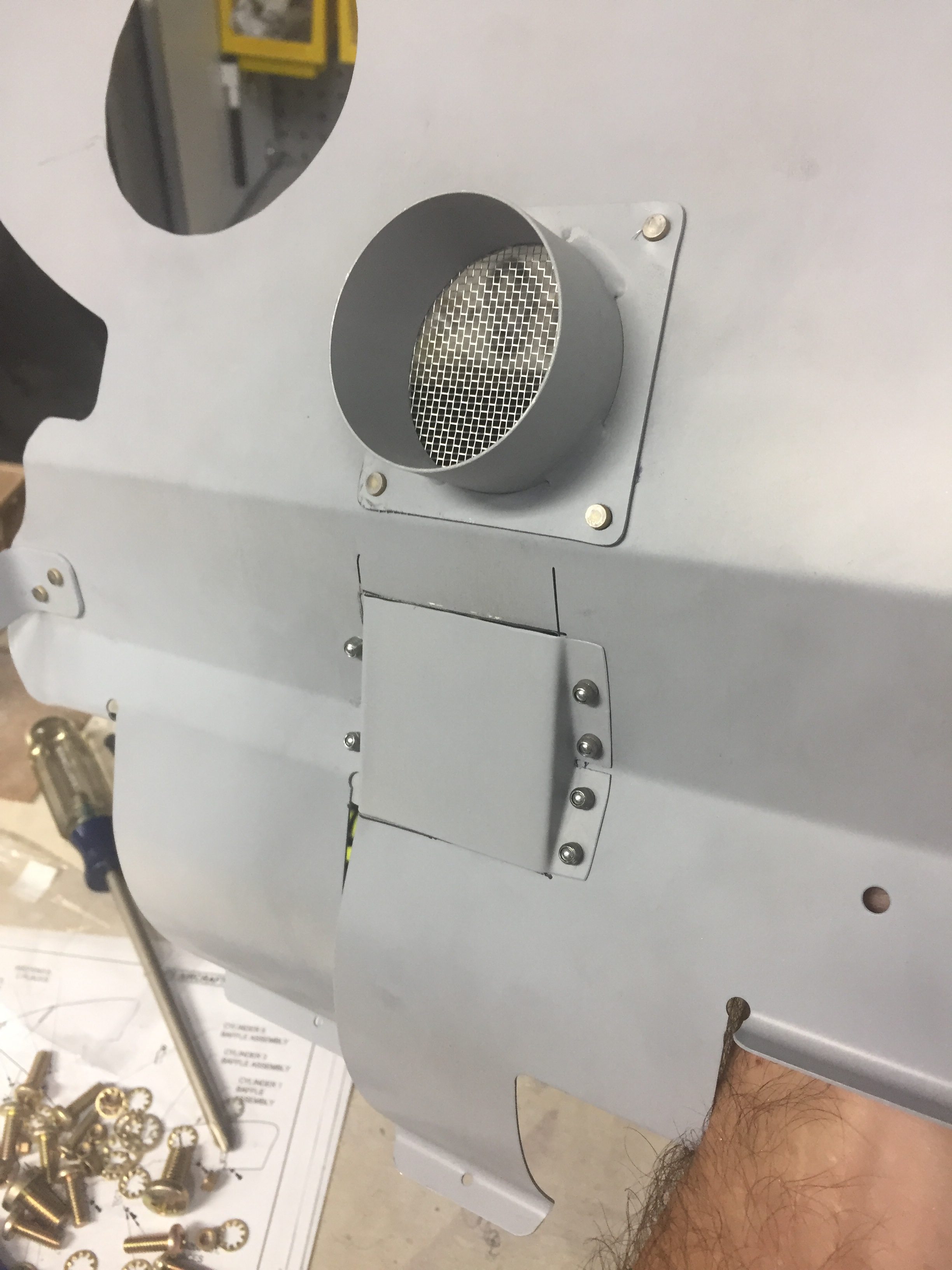
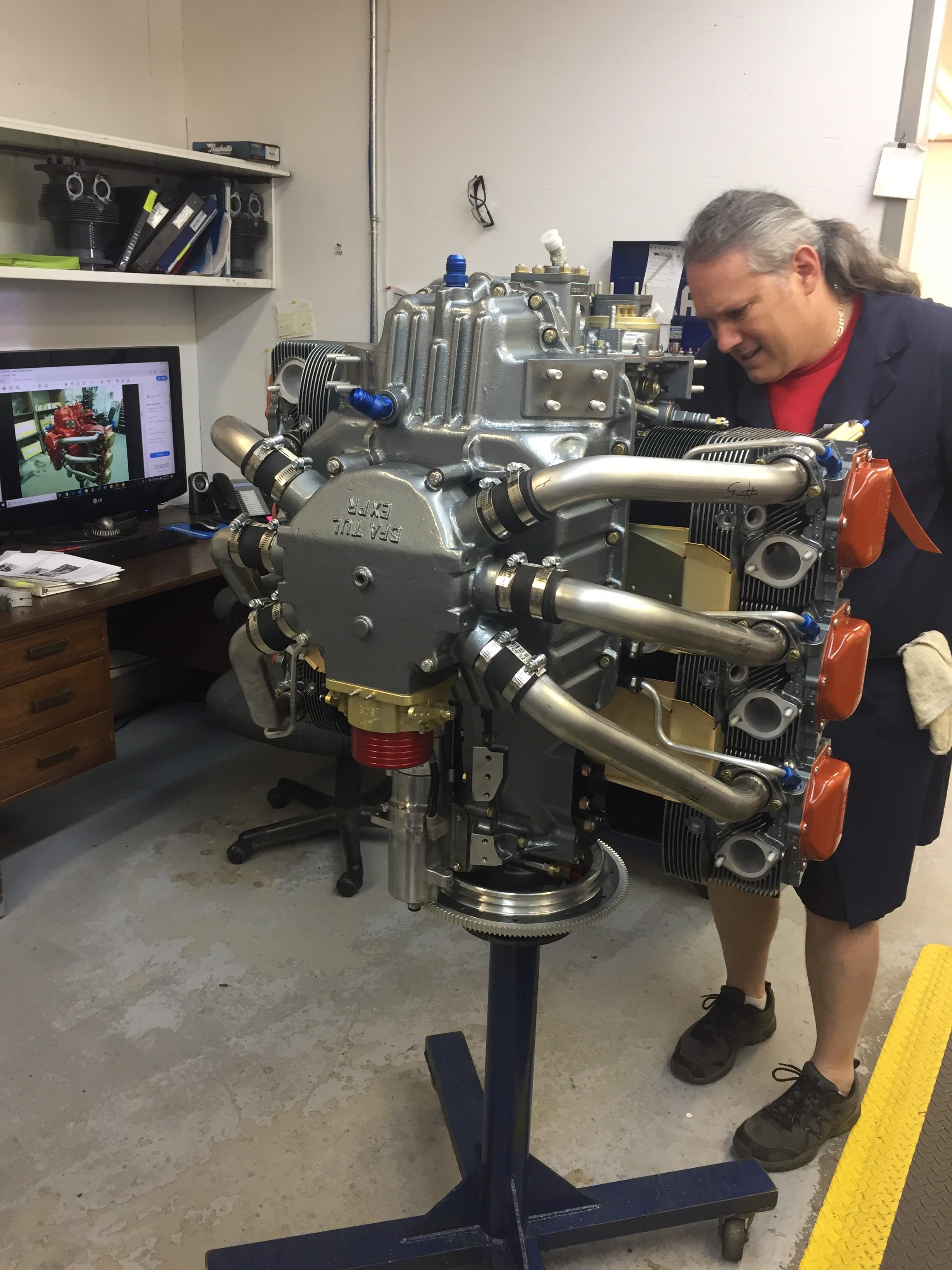
Once all the stock baffles are on, it was time to fit my RV Bits carbon fiber plenum.  I had this shipped all the way from South Africa and it’s a nice piece.  If someone wanted to create their own, it really wouldn’t be hard but it would take some time.  I positioned it to maximize the opening up front around the intakes but keep it clear of the cowl which should help keep the pressure higher on the cooling side.  That increases (in theory) the delta P between the high and low side of the engine as the hot air passing through the engine is sucked out the bottom of the cowl exit.  I initially drilled holes in the baffles and plenum but later redrilled the baffles after fitting the cowl (to be documented in a future post).
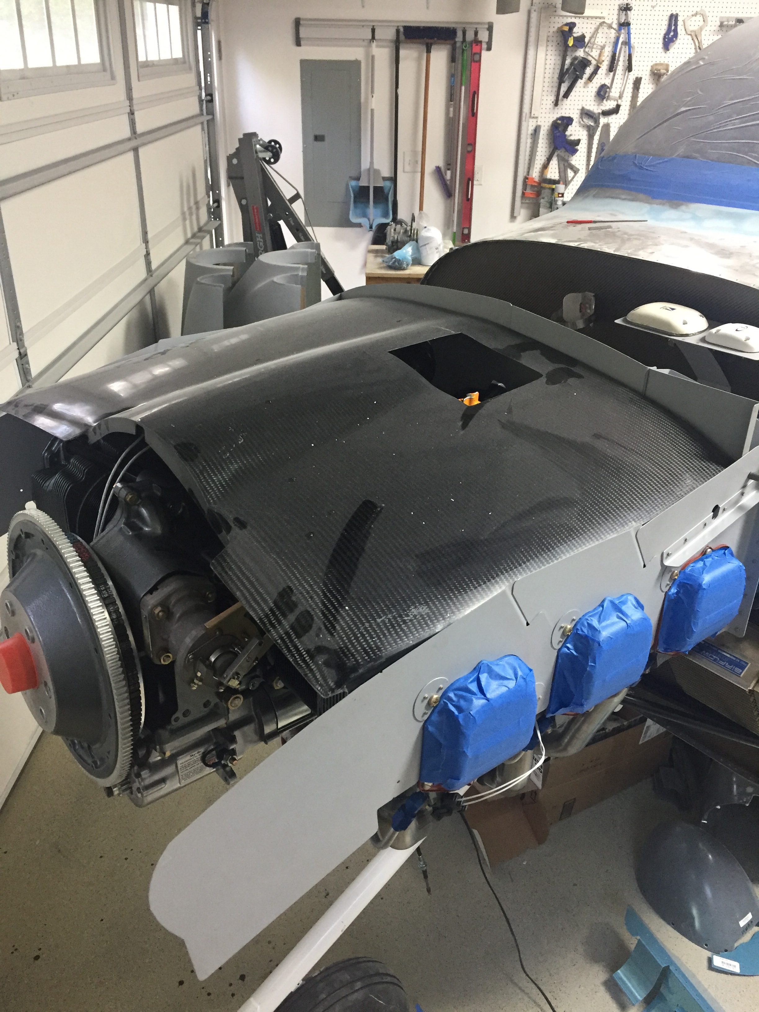
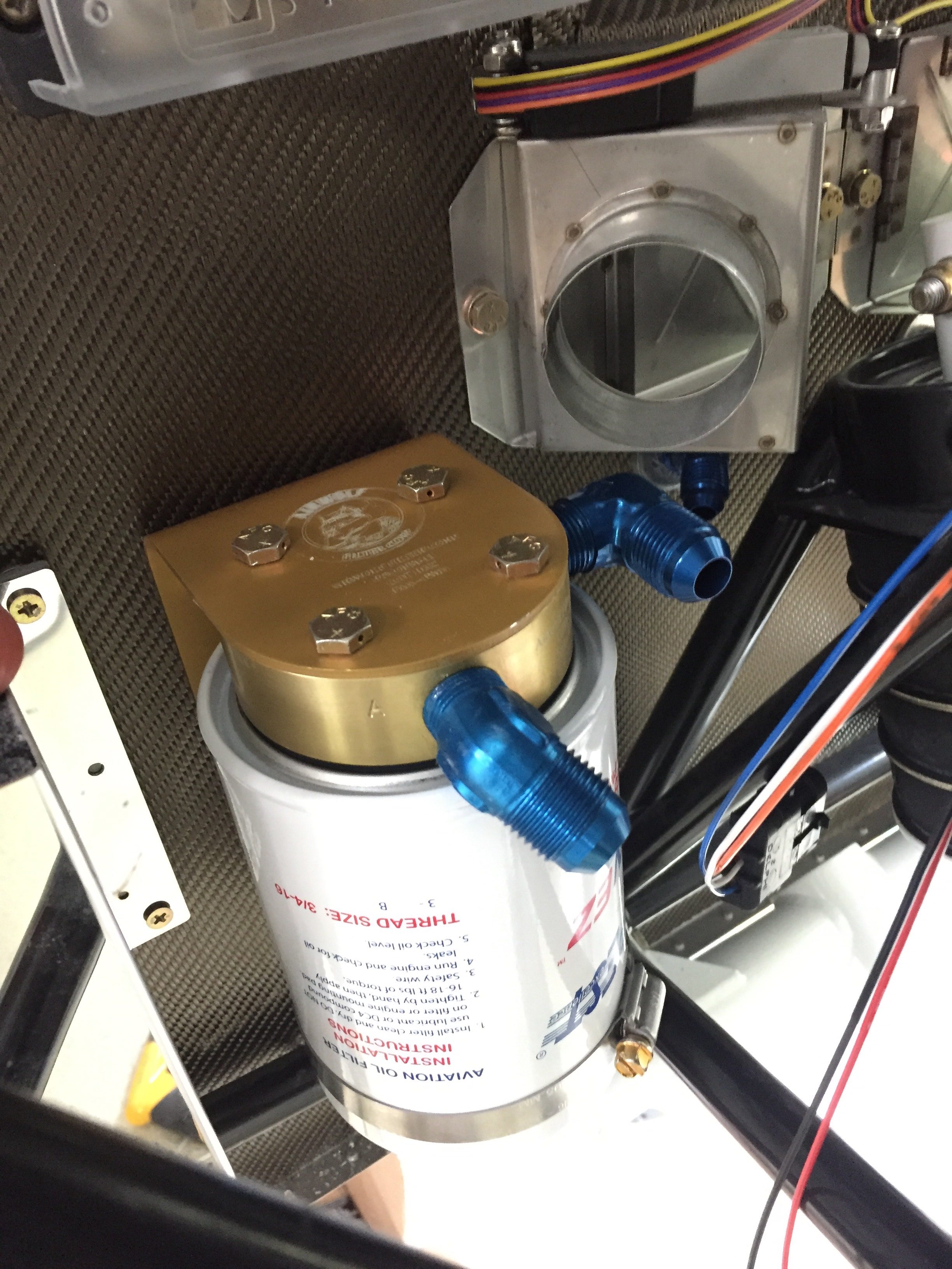
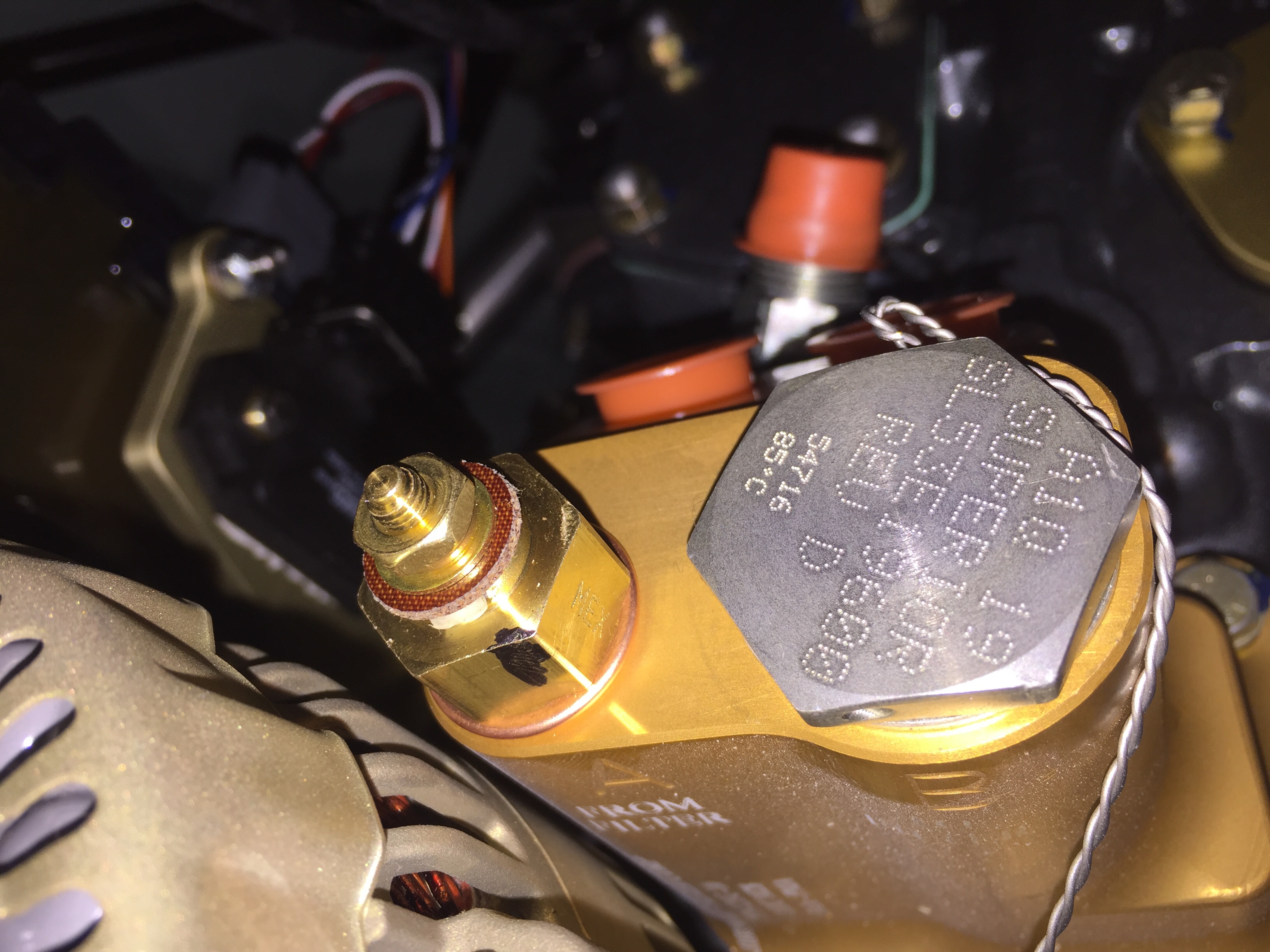
The Airwolf remote oil filter has a spot reserved low on the firewall near the battery box and wound up being perfectly placed.  I installed the brackets and doubler along with the fittings and tested the filter out.  The lines run up to an adapter that mounts on the accessory case and includes the vernatherm and oil temp sender.  This and a quick drain oil plug should make changing the oil a no-mess event.
Put some pants on

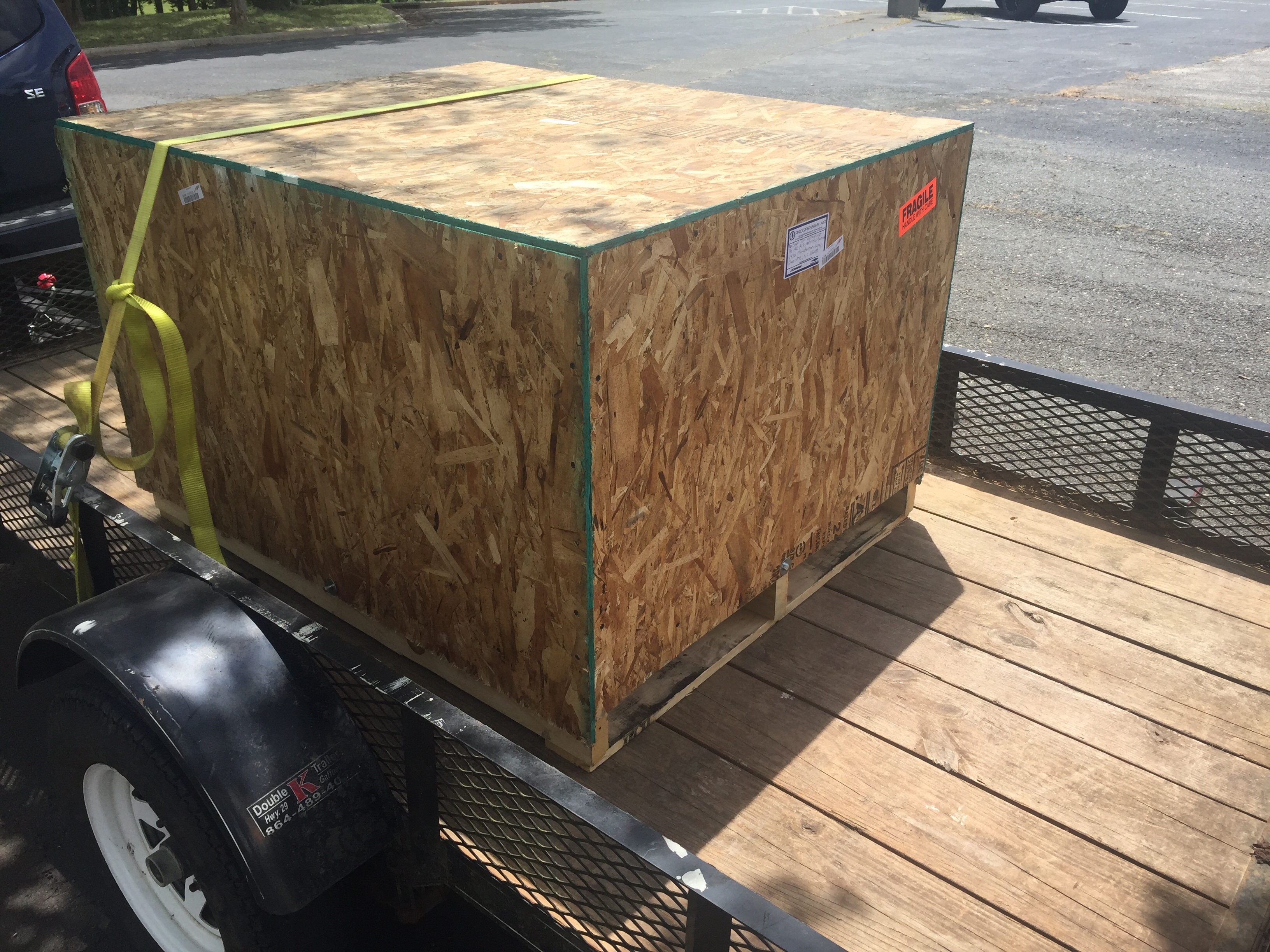
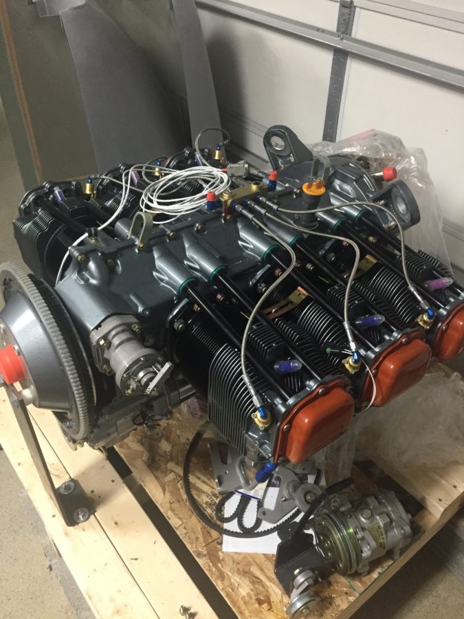
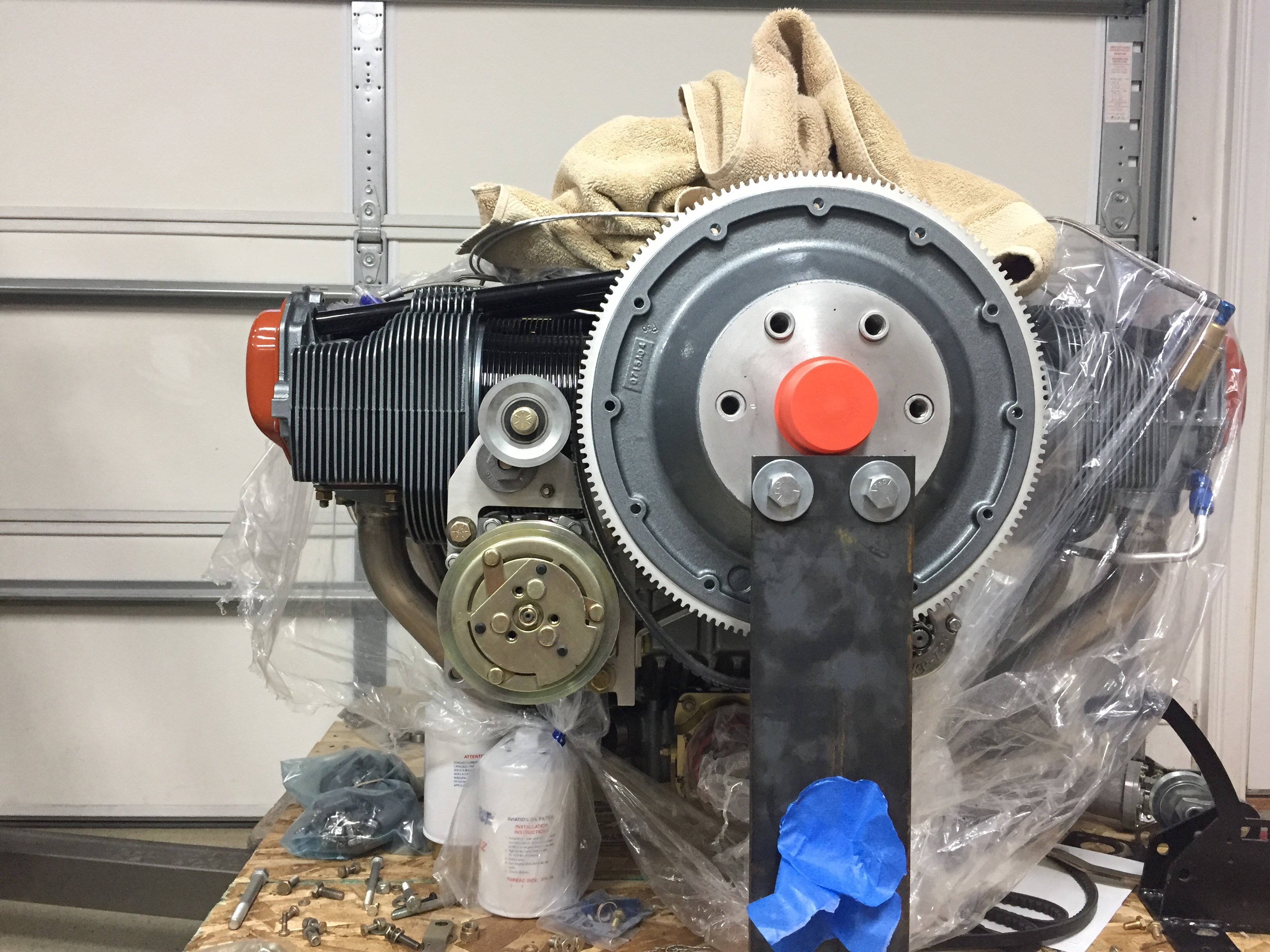
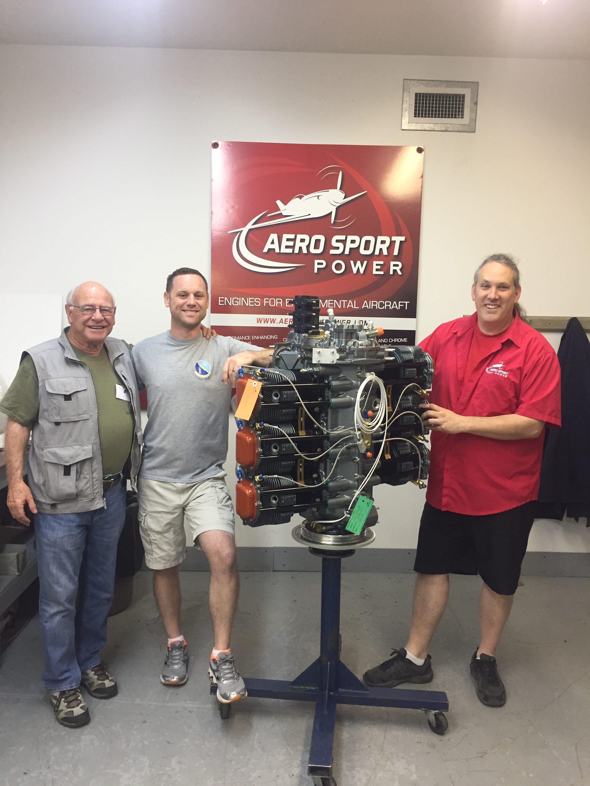
The last big delivery of the project arrived containing our engine in a pickled state from Aero Sport Power.  A huge thanks to the guys on base who have helped me get the deliveries and saved so much headache by avoiding home deliveries!  I loaded it on the trailer with a forklift and then got it off at home by disassembling the crate and using my engine hoist to lift it.  It worked out quite nicely and I used a few cinder blocks to rest the pallet on so I could put the hoist away.

The engine was preserved (pickled) by Aero Sport since it will be a few months before first flight.  This prevents rust and corrosion from setting in and keeps everything coated with a special rust inhibiting oil until I’m ready to fire it up.  I couldn’t help but bolt the prop governor on and start working on the aircon compressor install, as I’ve been concerned with that for some time.  We’re off to a lack luster start.  The studs for the prop governor were about 1/2″ short and had to be replaced.  My steep learning curve with threaded studs in a Lycoming equaled a four day project to remove them, but thanks to Amazon aircraft tool supply, a little heat, and a smack with a hammer (great tip Darren at Aero Sport, thanks) the studs finally backed right out.  I replaced them with longer studs which are ludicrously expensive for what they are and a week after I started, torqued the nuts on the prop governor.

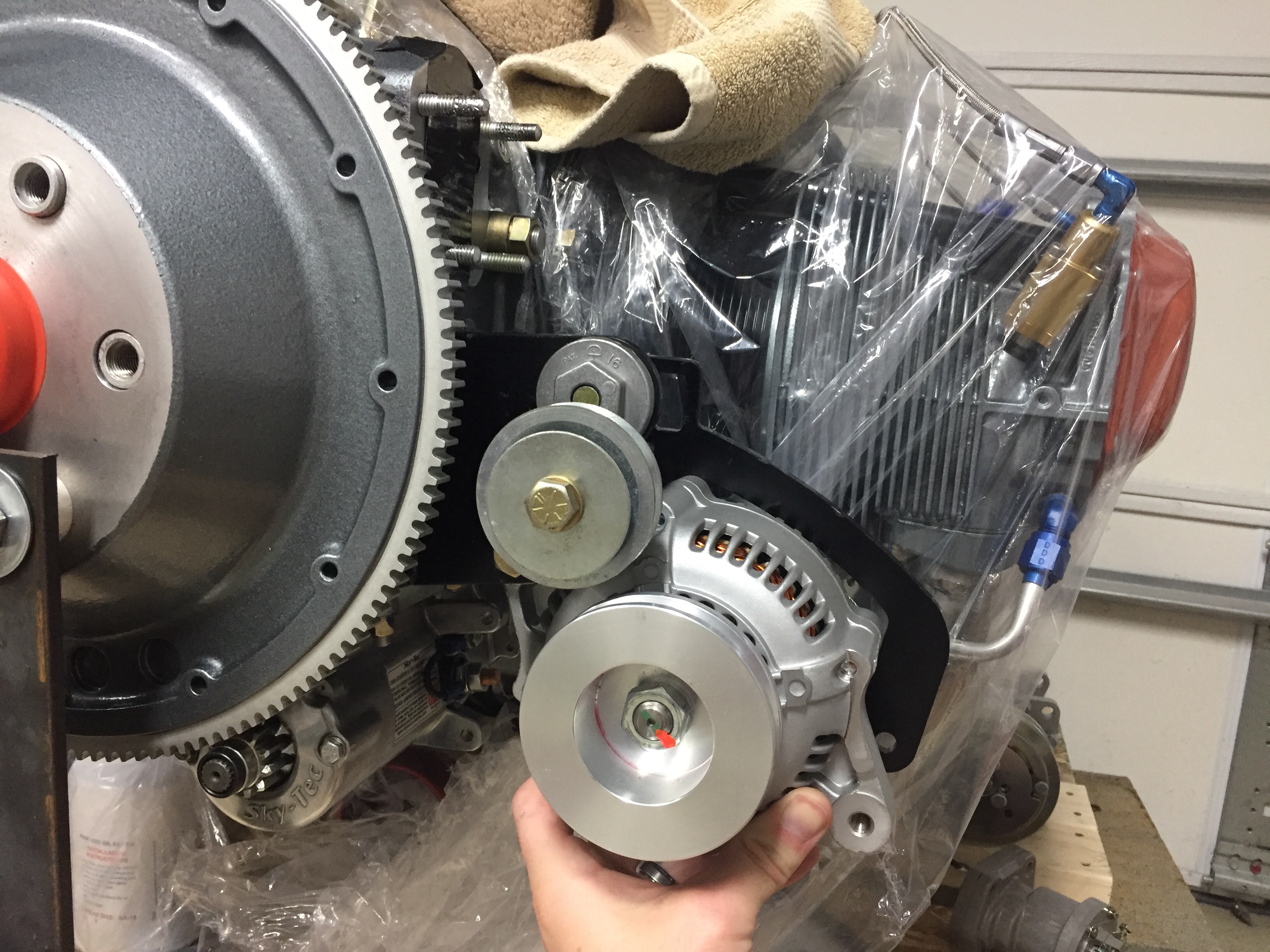
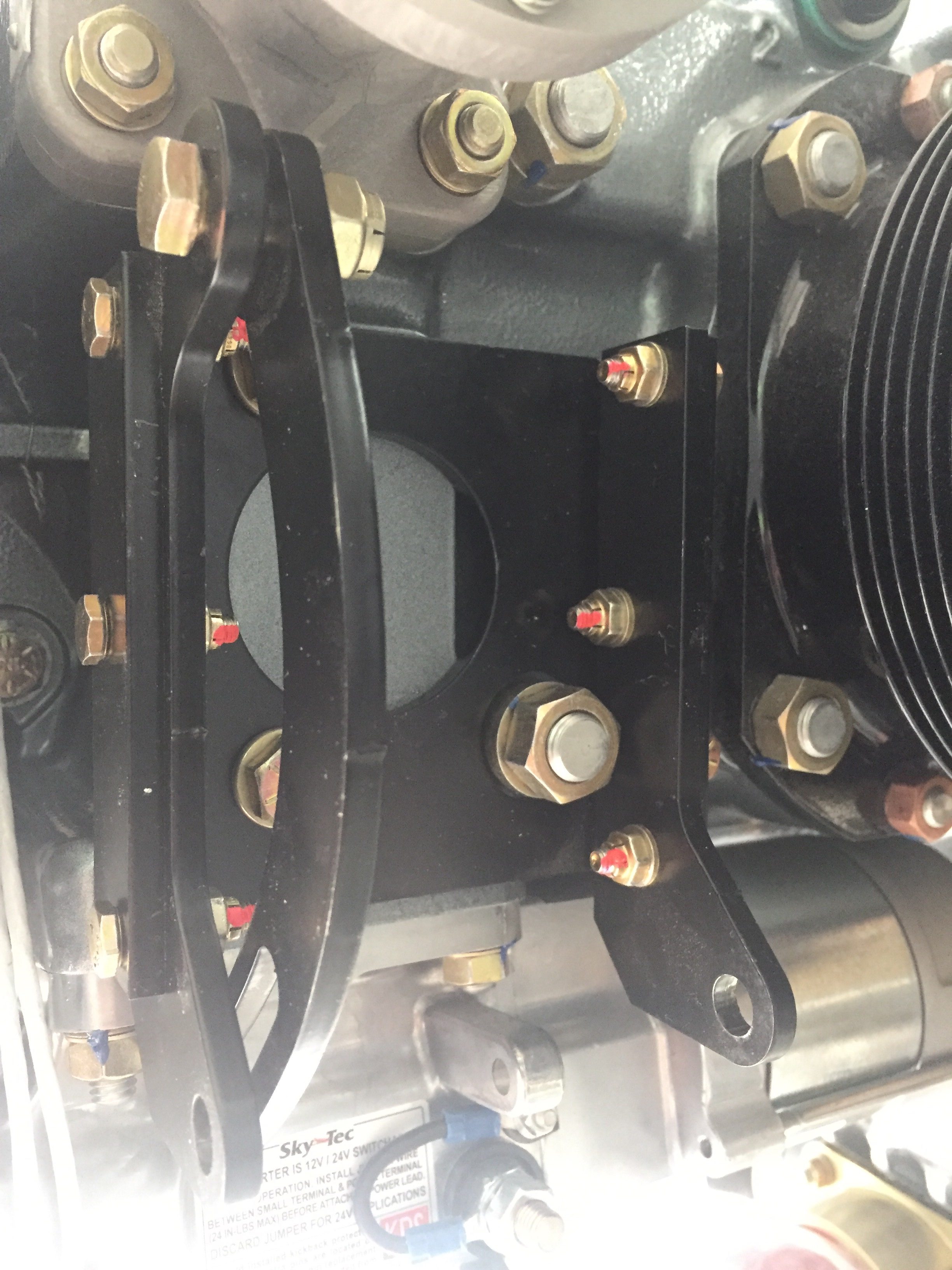
The aircon compressor was another swing and miss, not surprisingly I must admit.  I knew I had an original design bracket from Flightline and wasn’t sure if everything was going to work out.  My setup moves the alternator to the port side and puts the compressor on the starboard side.  Well, the brackets don’t allow the current compressor model to line up with the flywheel grooves.  The alternator also didn’t fit at all since the Plane Power alternators have a slightly smaller case than the antient models this was designed around.  Basically, nothing worked.

Of course, I had already taken everything apart and mixed hardware which was a huge mistake.  It took me an hour to sort things out and figure out where crap went back on the engine to be in original configuration.  Another call to John and Robert Skinner to brainstorm, I decided to push the easy button and buy the newest compressor and mount from Flightline.  That cost a lot, but I just don’t have the time, resources, or skills to engineer a new bracket and have it manufactured one off.  I know his newest setup works, so I sucked it up and paid the bill.

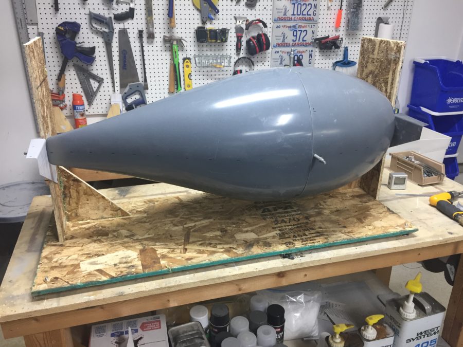
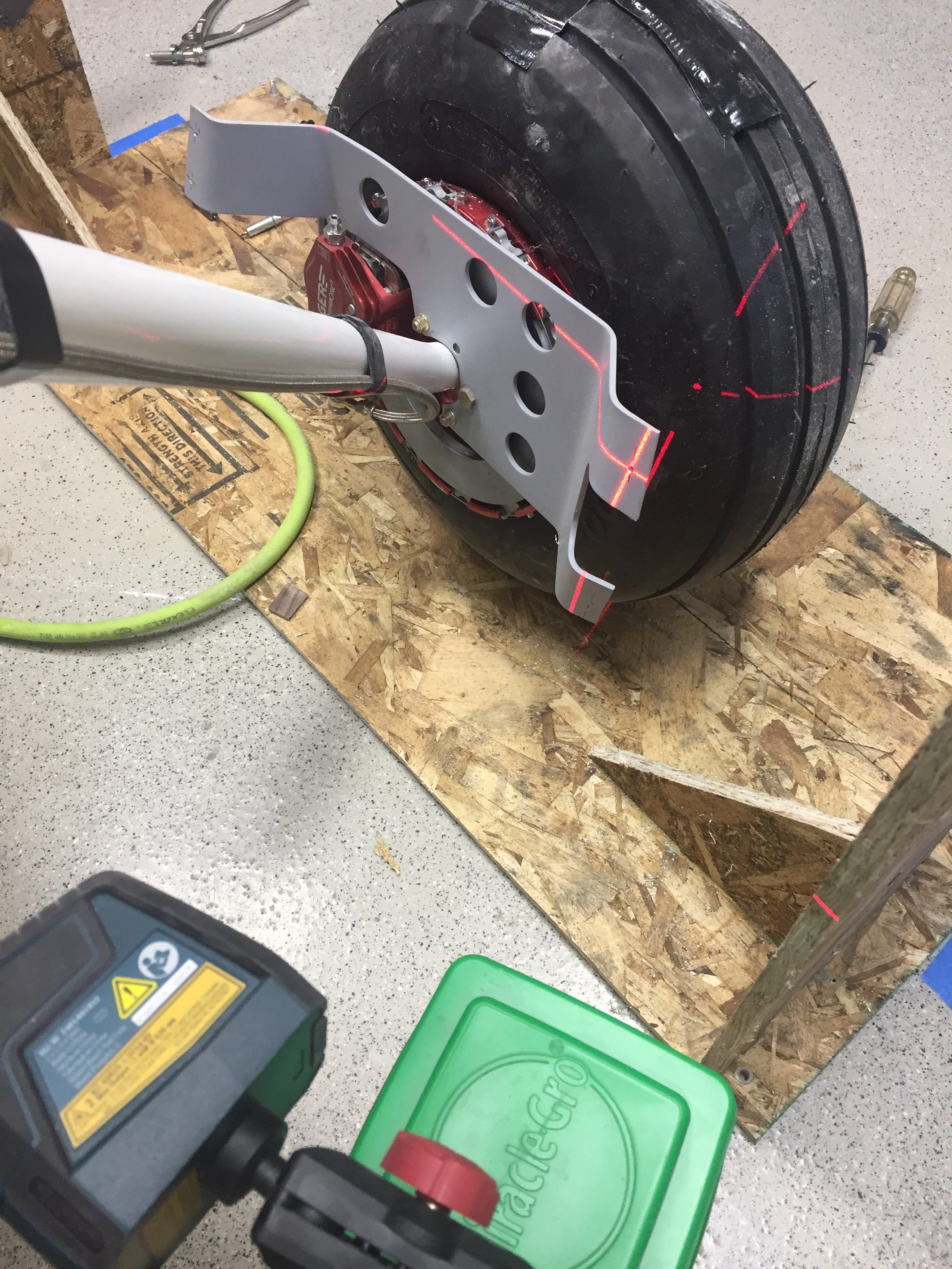
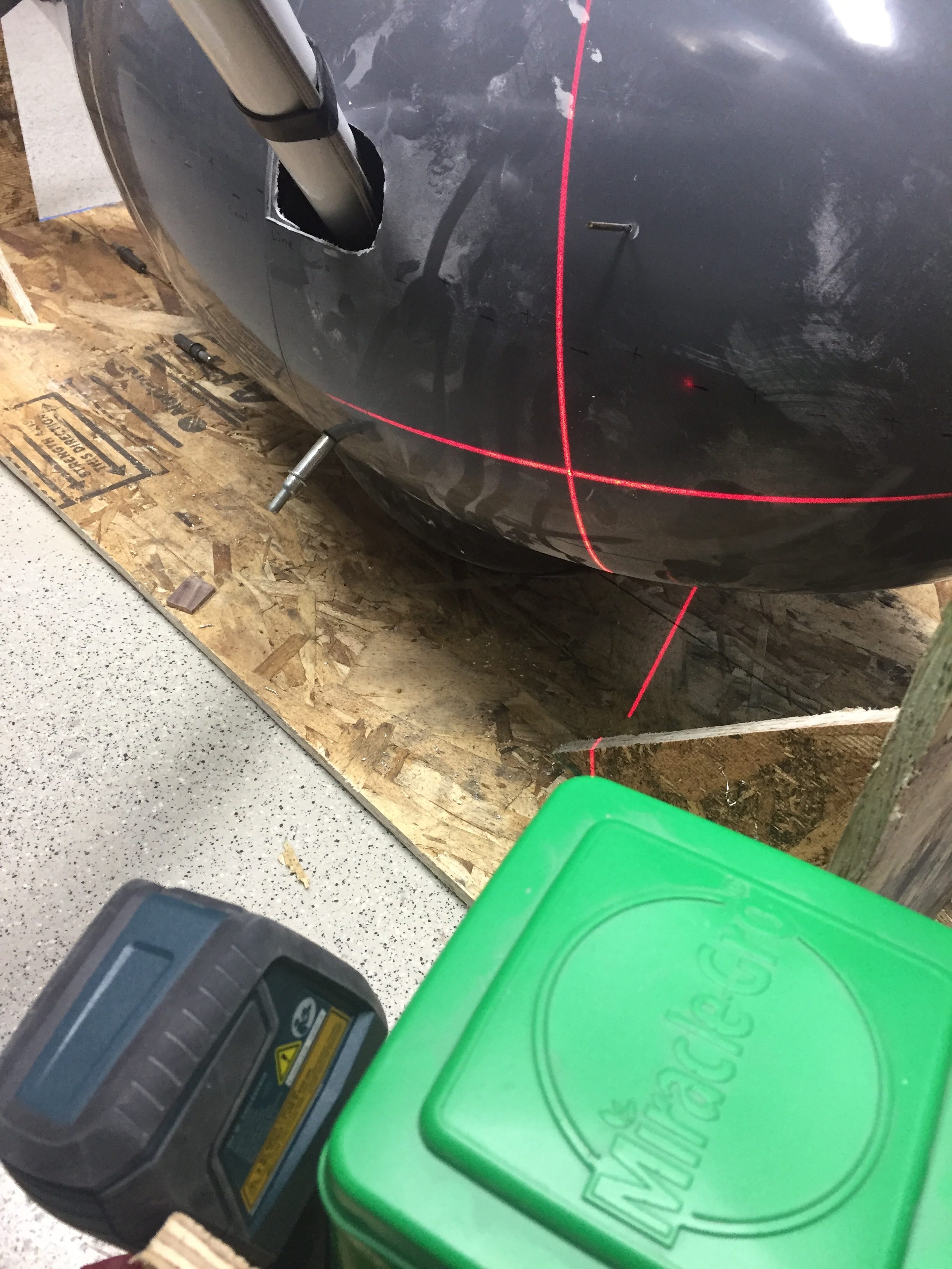
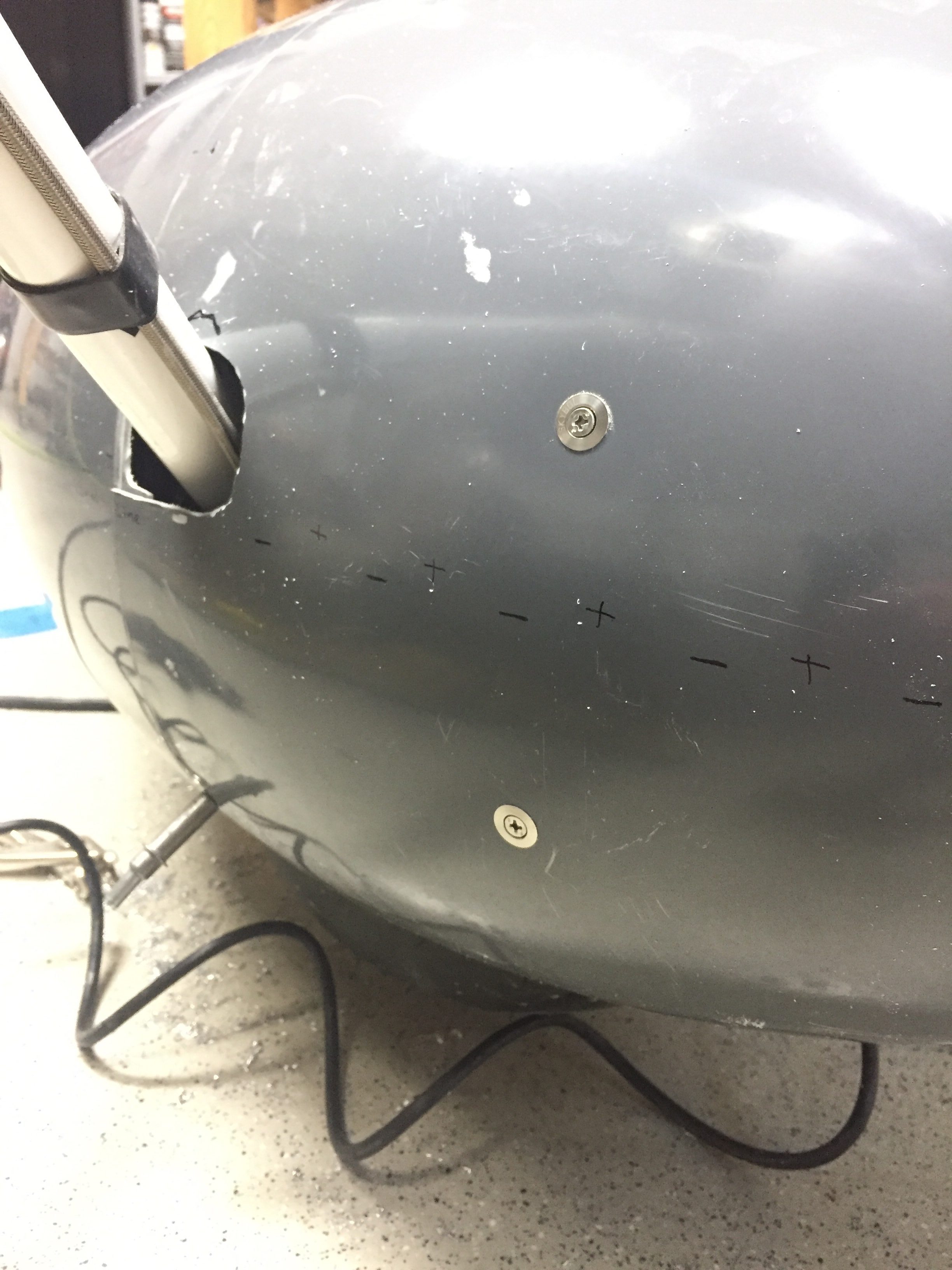
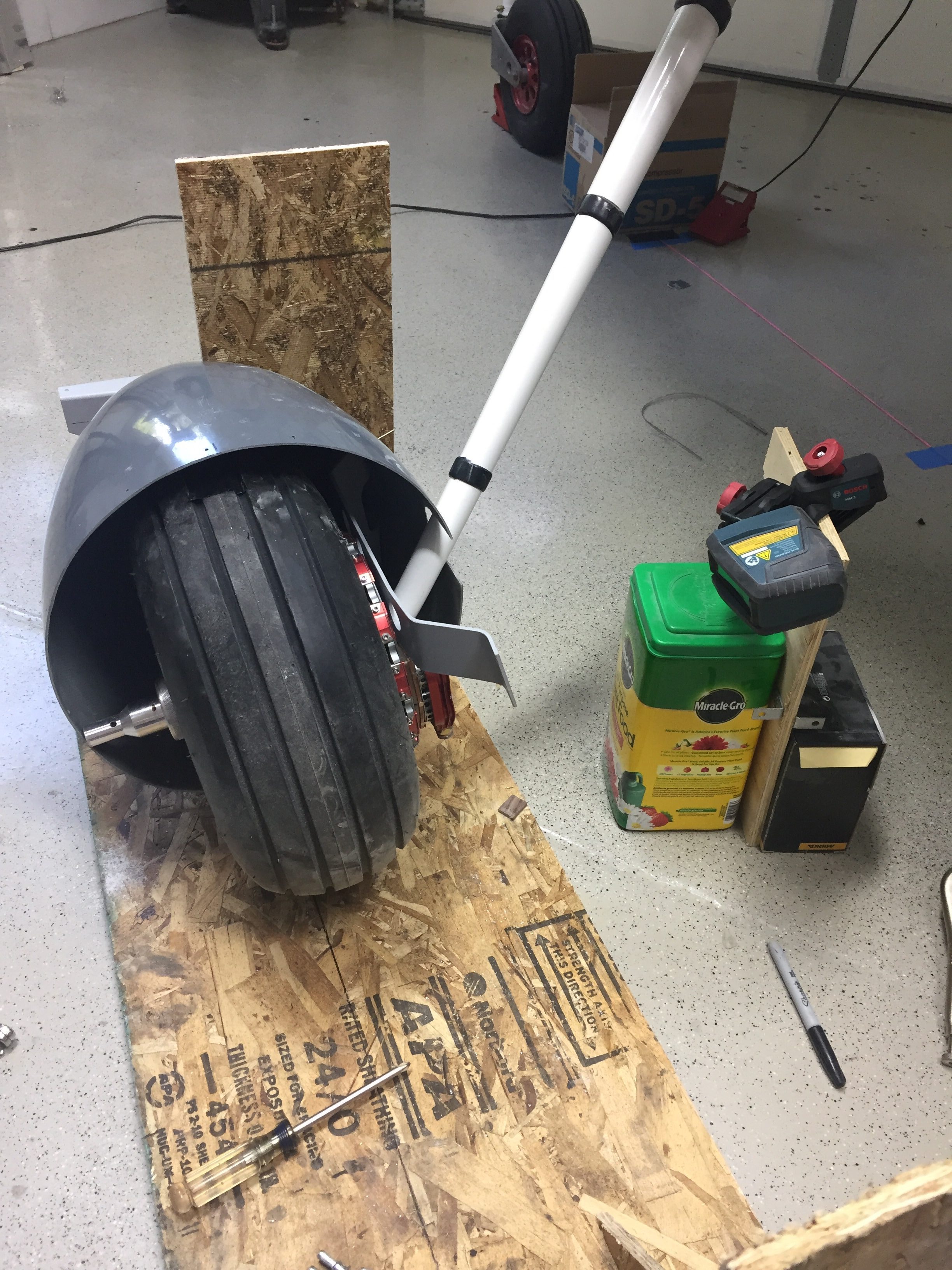
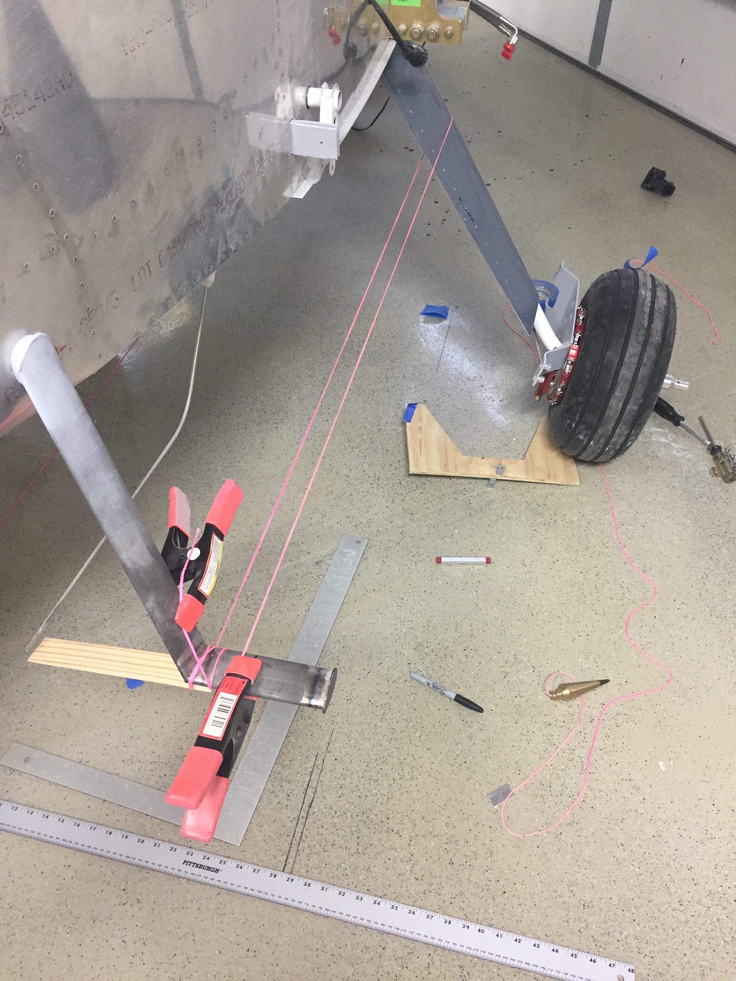
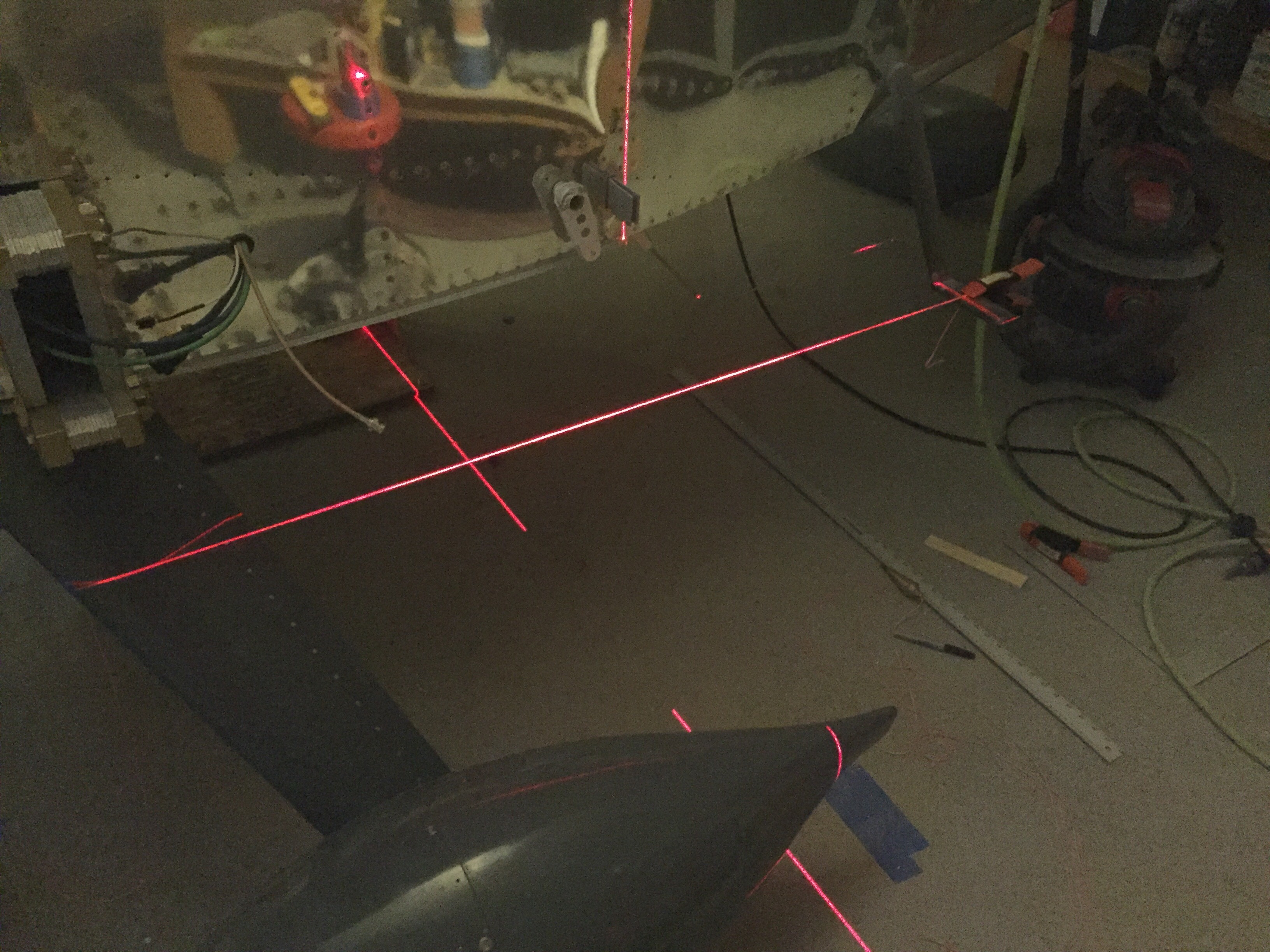
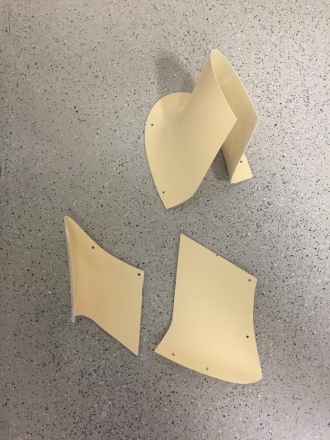
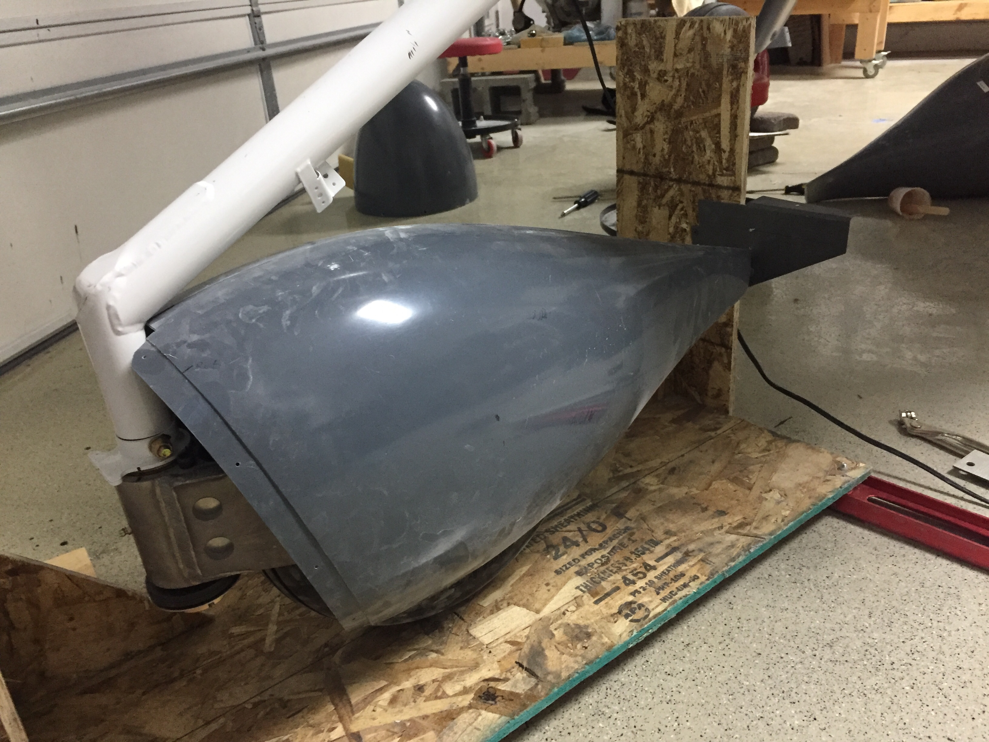
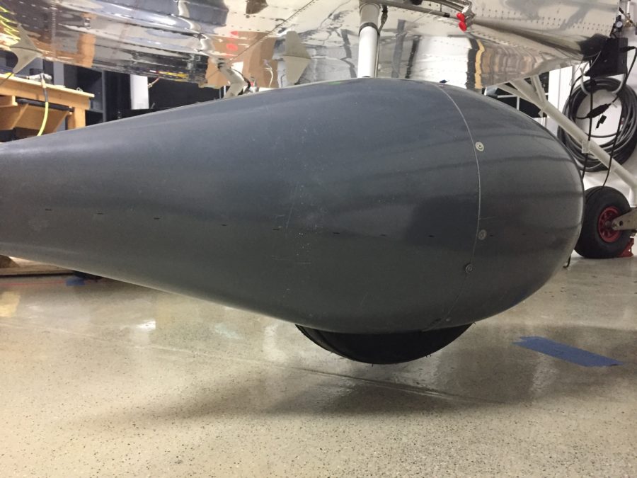
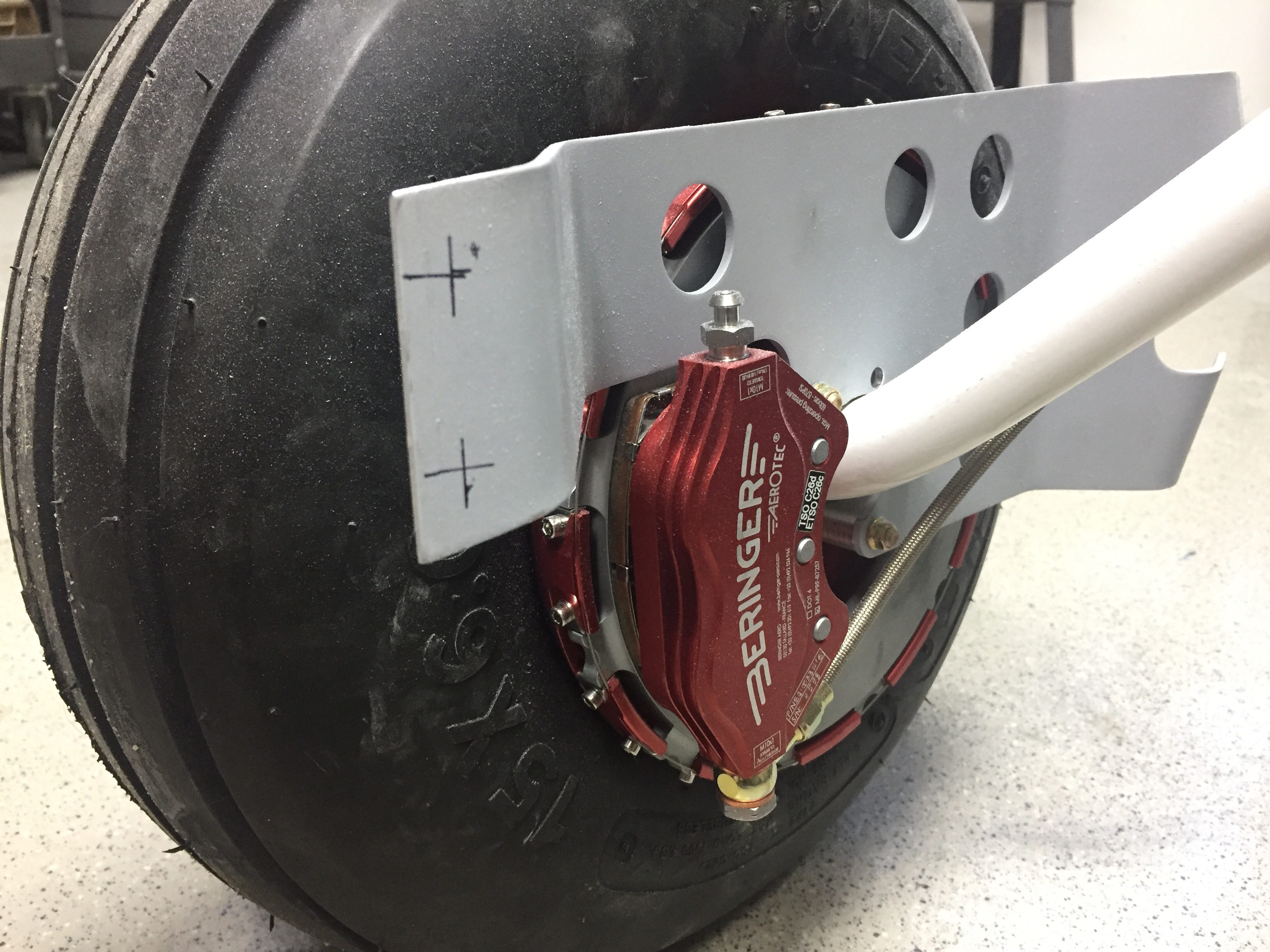
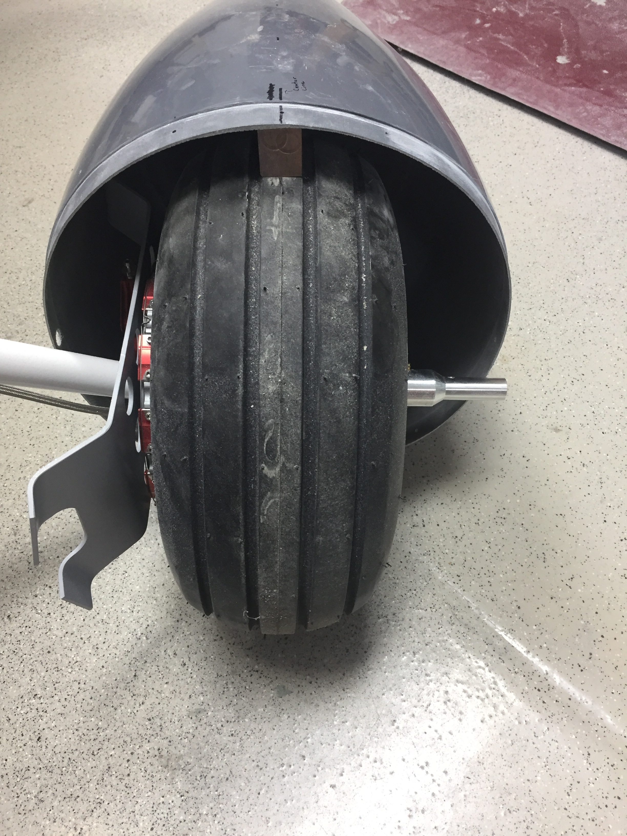
Meanwhile, the last project to do before hanging the engine is putting some pants over the beautiful red Beringer wheels.  The wheel pants and gear leg fairings add considerable efficiency to the airframe so it’s important to get these right and rigged properly.  I’ve dreaded them and was right in doing so.  For some reason, these were just a royal pain in the ass for me.  I started by building a jig to hold the main paints.  I used a laser to get all of the level and plumb lines which sucked.  Then I cleaned the two havles up enough to joing them together which also sucked.  What really sucked was trying to get the alignment perfect and the holes drilled in the right spots.

It sucked getting up and down off the floor about 50 times an hour too.  How was aligning the pants in the jig with the airframe?  It sucked.  I dropped a centerline for the fuse and then measured from that to set the alignment.  What sucks, is the new pants from Vans are grey fiberglass gel coat so you can’t see through them.  Which is why the directions suck because they assume you can just shine a light through the pants marking the proper holes to drill.  I finally sucked it up and used a combination of careful measurements and the laser to pinpoint the locations to drill into the pants and mounting brackets.

It also sucks trying to mark the wheel area to be cut out because you essentially have to mold yourself into the concrete floor to look underneath the pant that is three inches off the ground.  I’m using SkyBolts on the wheel pants, which suck to install, but will make maintenance and access so much easier in the long run.  I had to drill out the mounting holes slowly to ensure alignment stayed true, but they came out nicely in the end.  It also sucked that I forgot my wheel pant axle stand off was an aftermarket purchase to replace the stock Vans part which – you guessed it, sucked.  The stand off was way too long (by design) but I was afraid to trim it.  Eventually, like Tess’s wheels, I put my big boy pants on and cut the damn things off to length, never looking back.

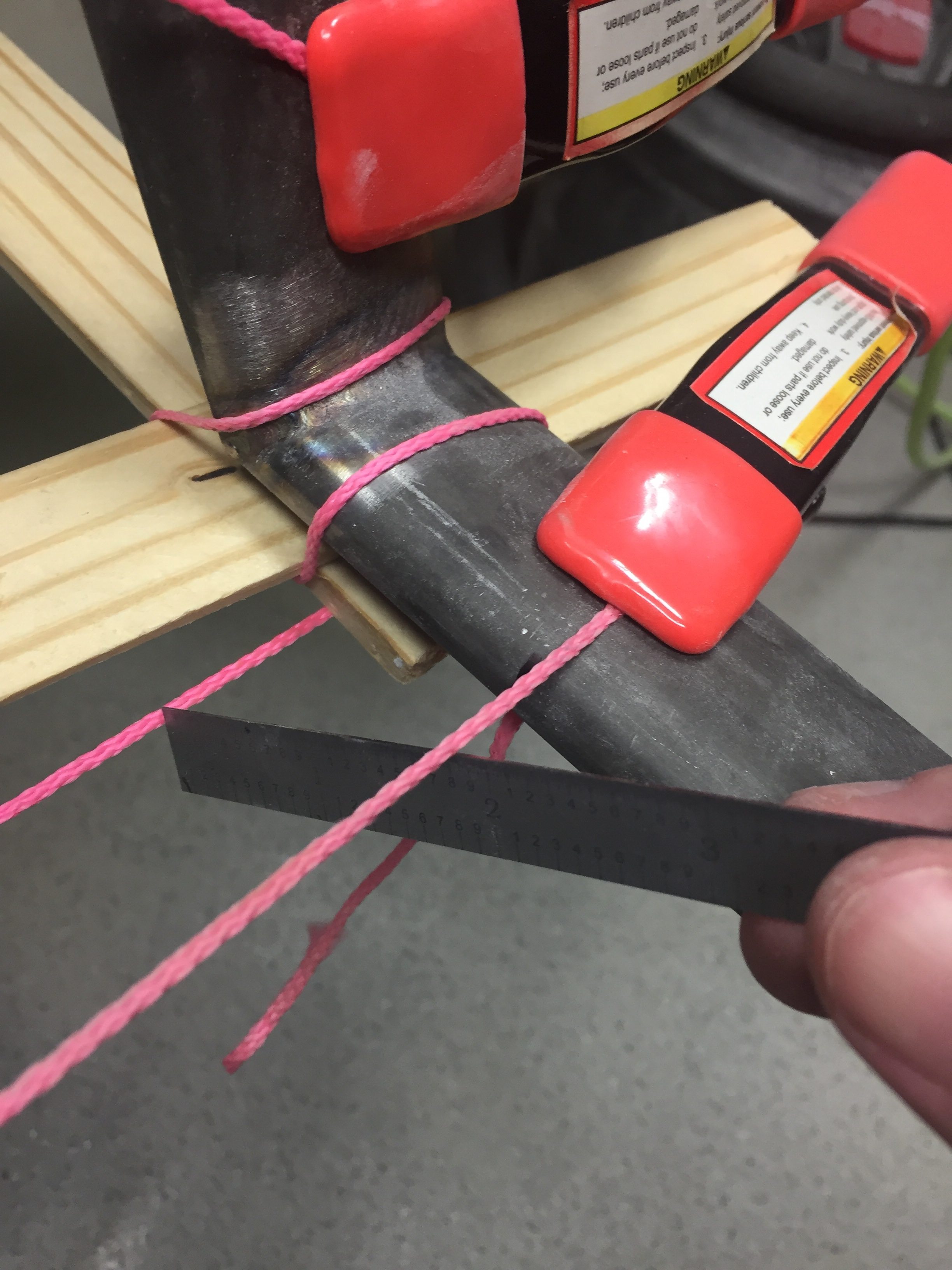
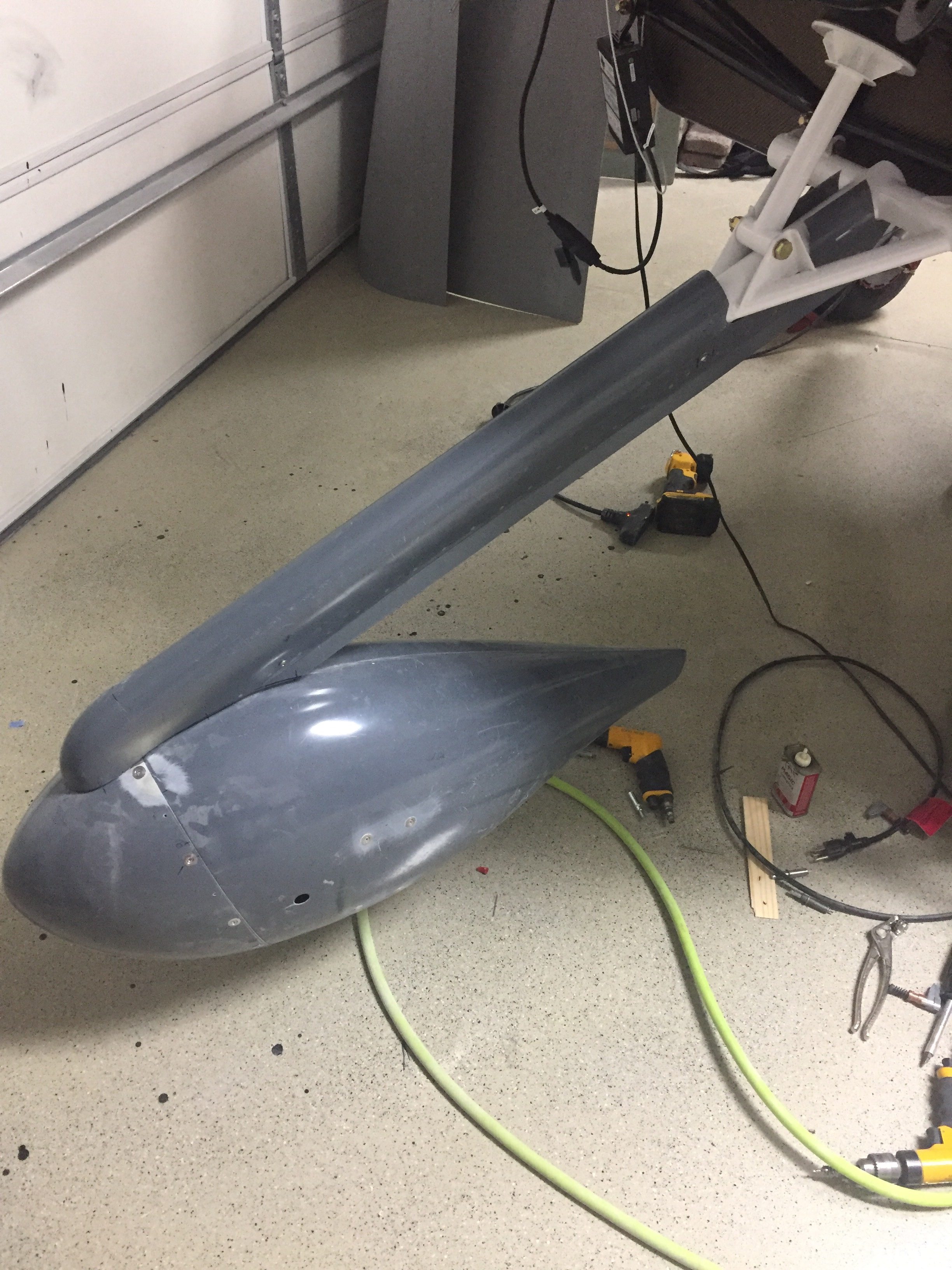
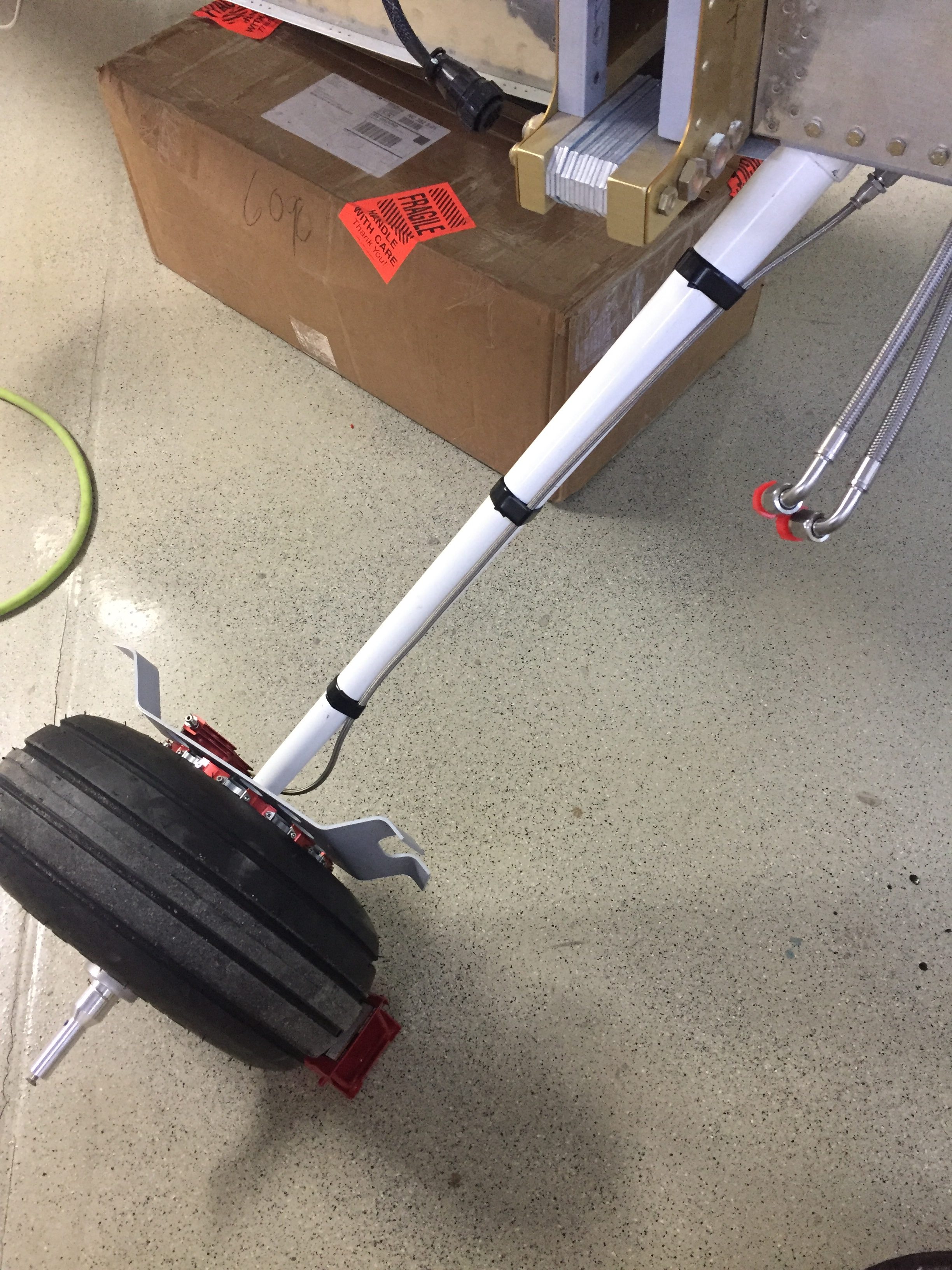
But wait, that was the easy part!  The second sucky task was to do the gear leg fairings that cover the legs and brake lines.  Hide your house cats, because you have to use about 25 yards of string through all of this.  Wrapping string around the gear leg fairings and steps, you use that to align them with the prevailing wind in flight.  I can’t even begin to describe how I did it, but it worked.  Measuring, plumb bobs, levels, digital inclimometers, string, lasers, string, and lots of painters tape and string plus some more string all sucked into one giant suck.

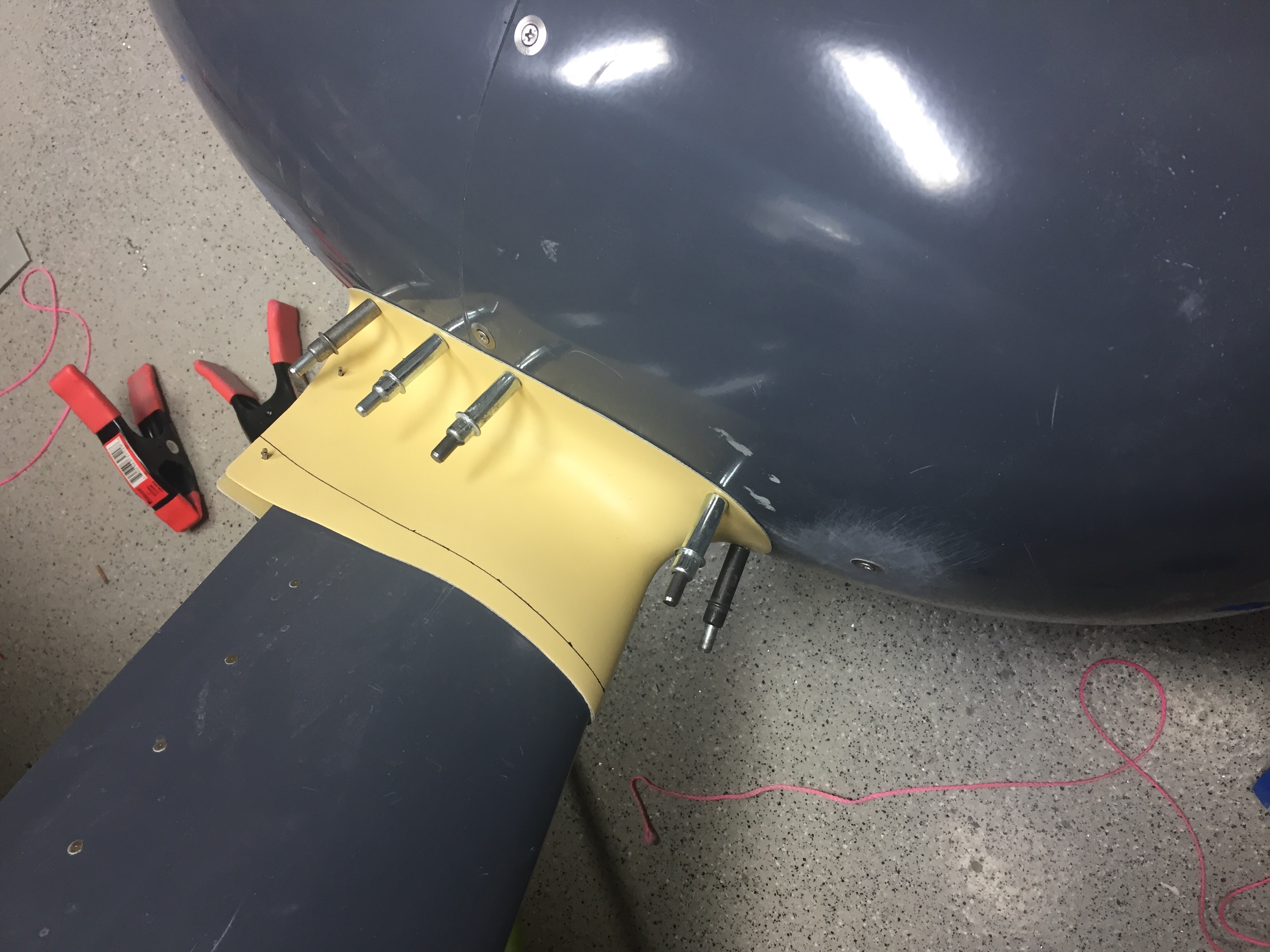
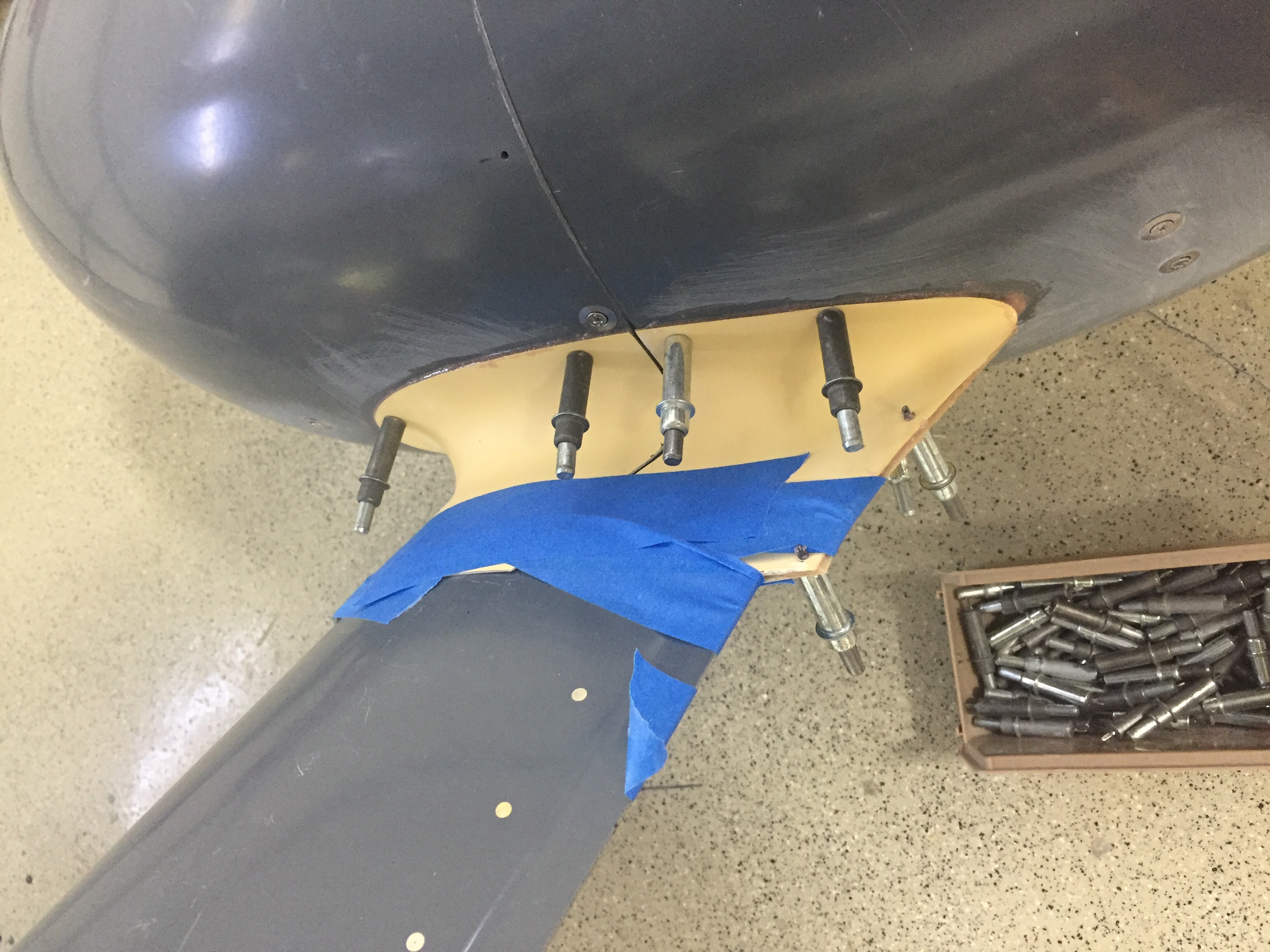
In the end, it was worth the work to have properly aligned and nice looking pants.  I’m often complimented on my pants, and now my airplane will be as well.  I repeated much of the process for the nose gear using the workbench and engine hoist to level the fuselage off the ground as in flight condition..  I trimmed my nose gear leg fairing a bit too much, so may add a bit more material back before paint, but it’s fine for now.  I also attached the RV Bits intersection fairings and chose to split them with the pants as others have done instead of per plans.  This does not suck and makes for a much cleaner look in my opinion.  I epoxied them in place and will finish the filler and sanding work later after initial flights to save build time now.

Phew, even writing that sucked.  Enough of that, let’s hang an engine!

Splash of color and an Oops

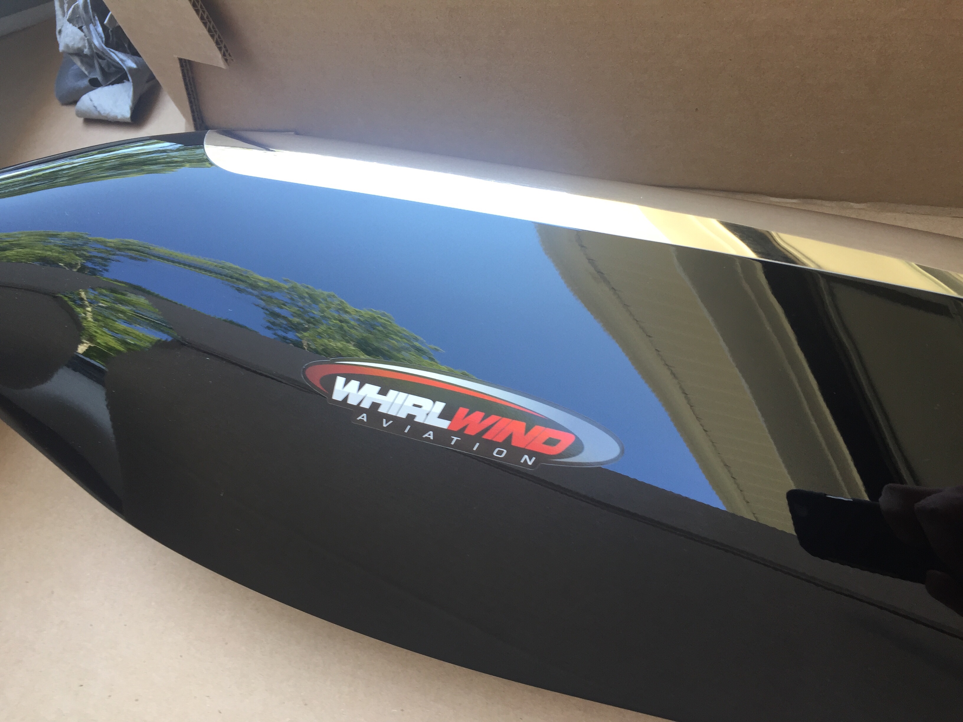
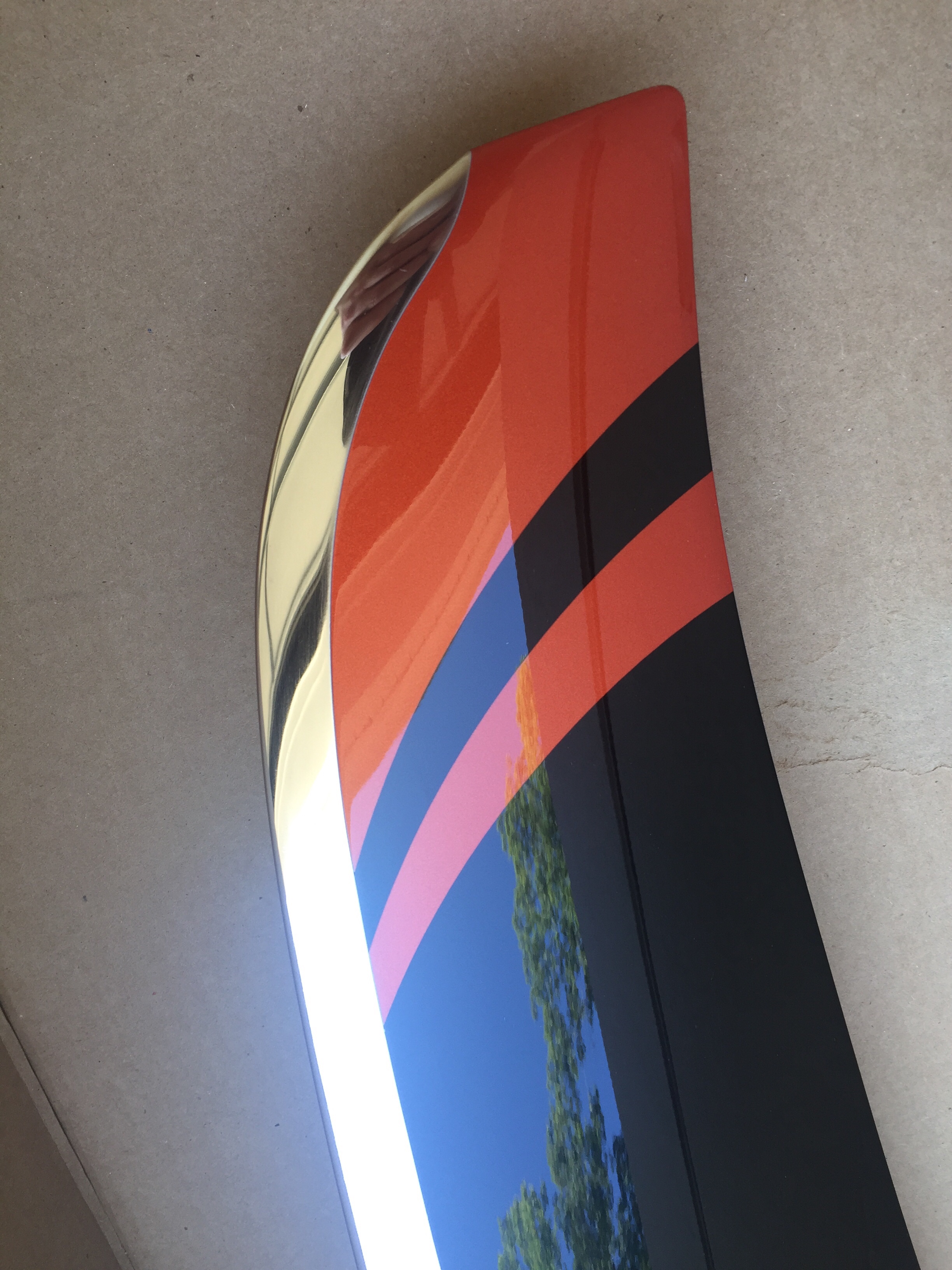
After returning from our trip up north, only a few days passed until we received a big package with a piece of art inside.  Our (second) propeller has arrived!  Whirl Wind delivered about a week late, but with prior coordination and communication with me so I was super excited to see what it looked like.  As chronicled earlier in the build, I purchased a propeller but decided to sell it instead of it hanging on the wall for three years before I was ready for it.  Joe Keys, you can’t have this one.  I knew I wanted another WW and the HRT blade is now a refined blade profile and is simply stunning.  Our orange was color matched and looks great with the black and nickel leading edge.  For now, the prop will go to a friend’s hangar to hang out with the wings until we move to the airport.

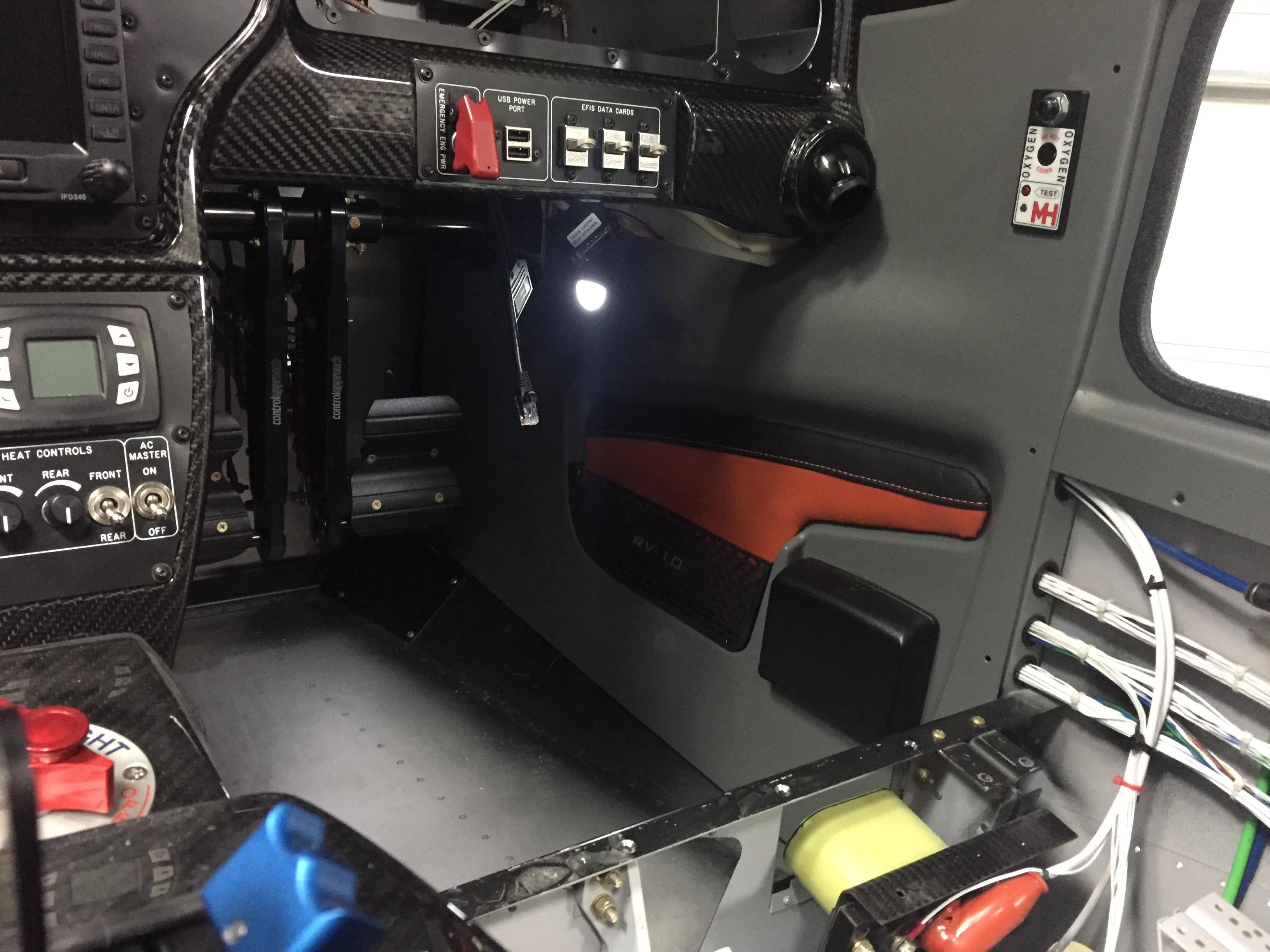
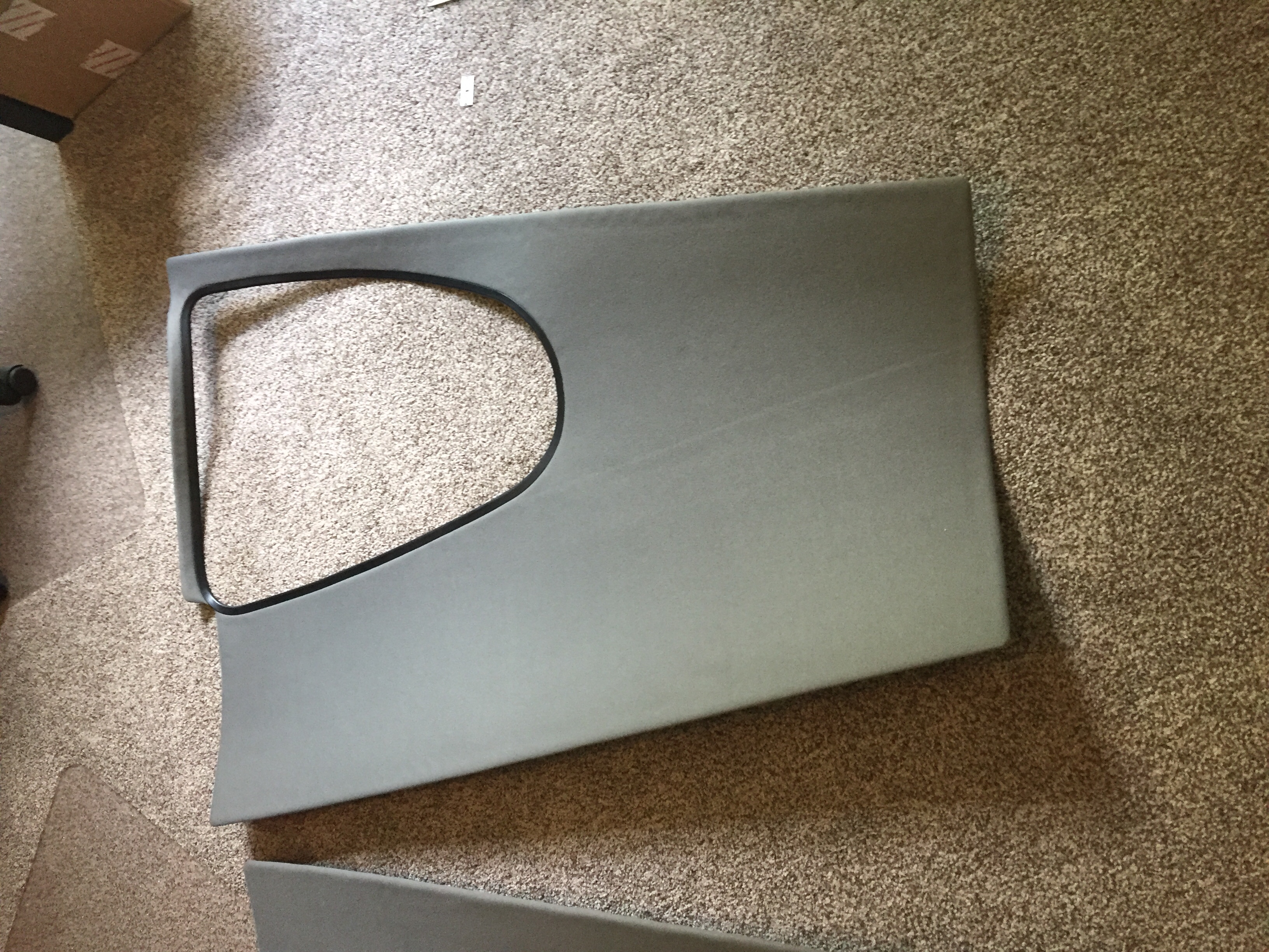
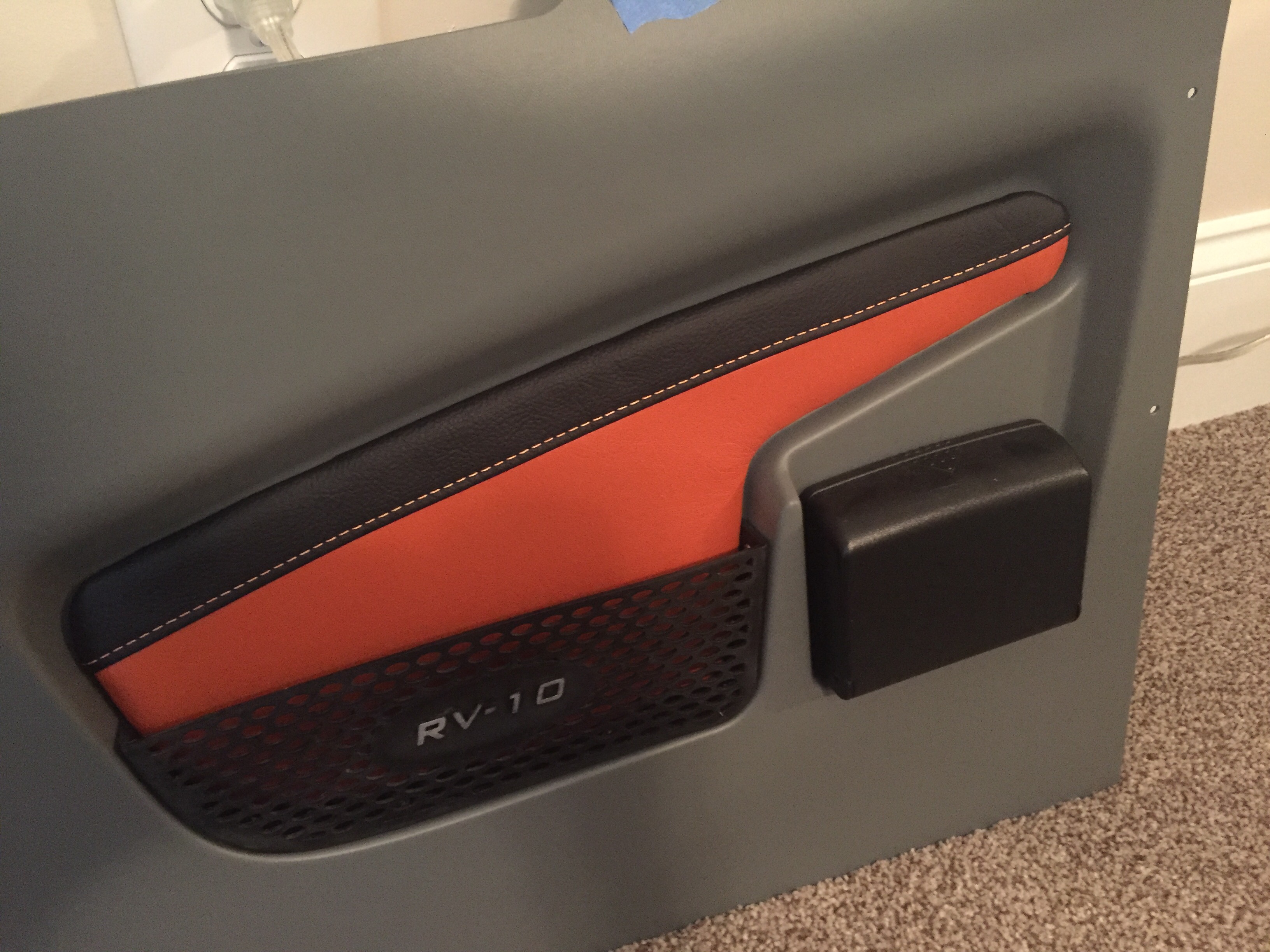
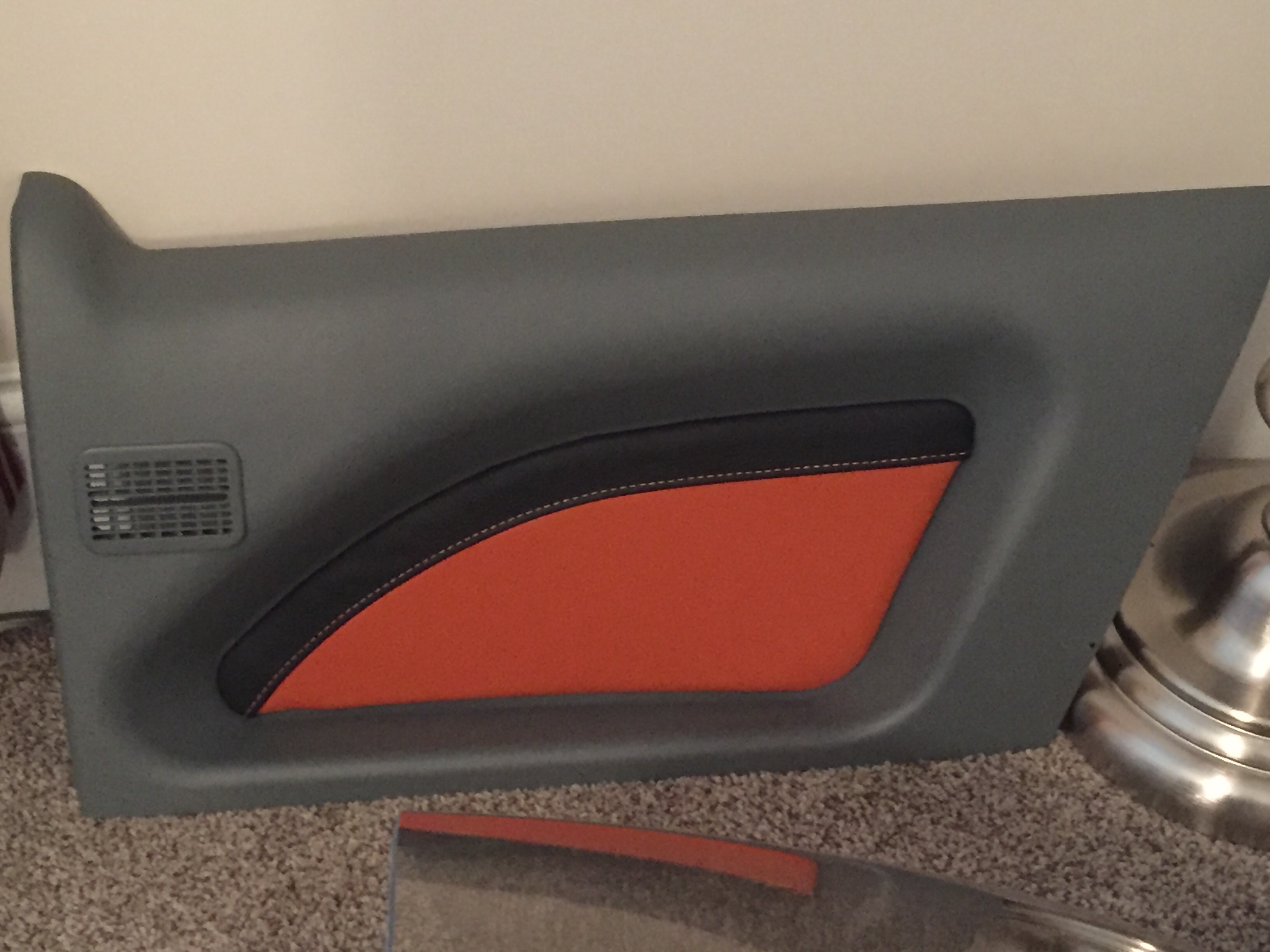
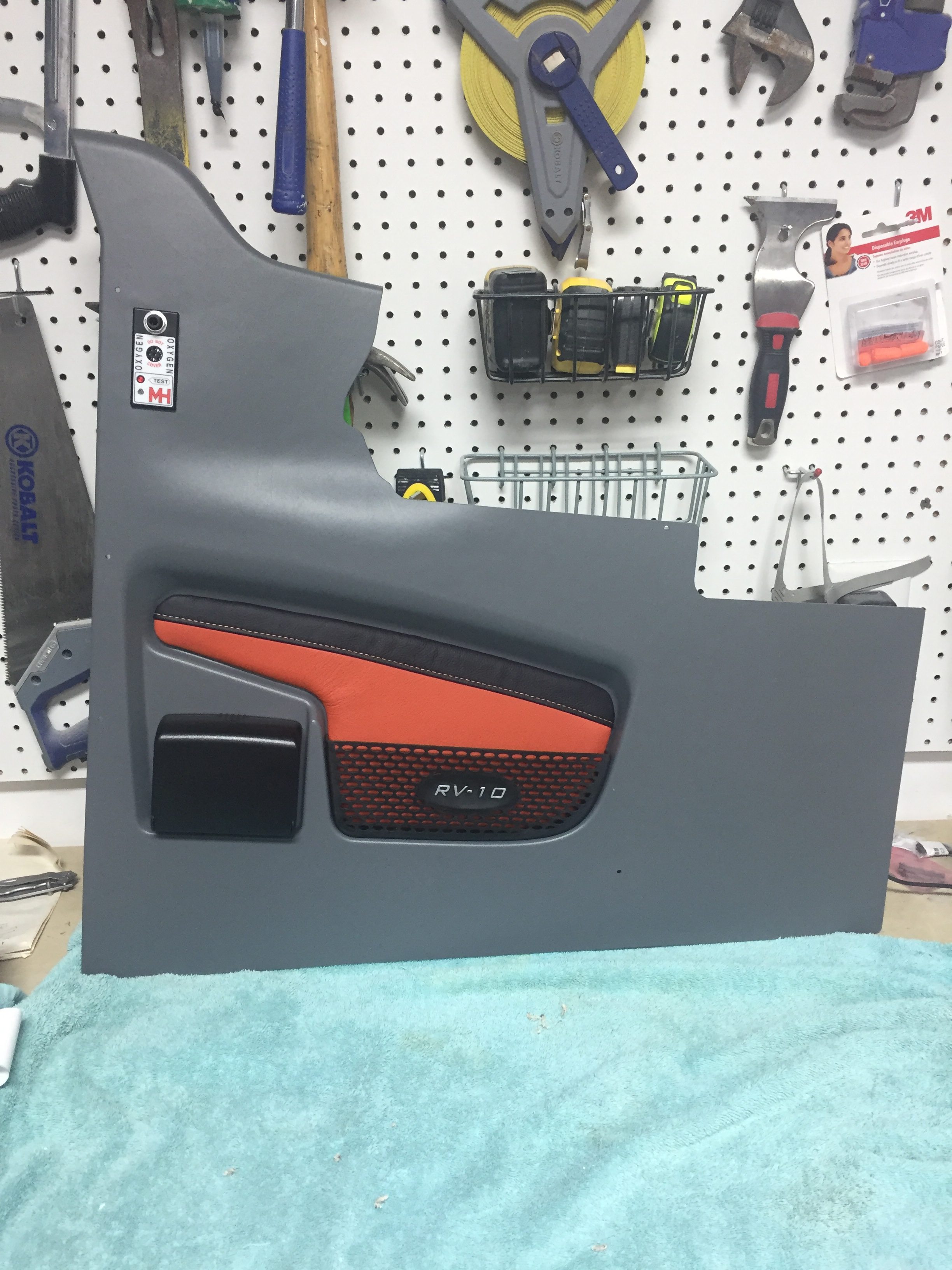
Adding even more color, I finished up the last of the wire bundling on the cabin sidewalls and went ahead installing the side panels with leather inserts.  They had been trimmed and painted for some time but I held off pulling them in and out until I knew I was done.  I spoke to Vic Syracuse who will be my DAR for airworthiness inspection prior to putting these in, as I wasn’t sure how open he wanted the airplane.  He advised to have it essentially flight ready except for rear pax tunnel cover (to inspect the elevator bell crank), cowling, and tunnel access panel.  This is the first time I’ve hooked up the foot well lights and I’m really pleased with the amount of light they give off.  It’s just enough for convenience while not quite enough to perform surgery on the floorboard.

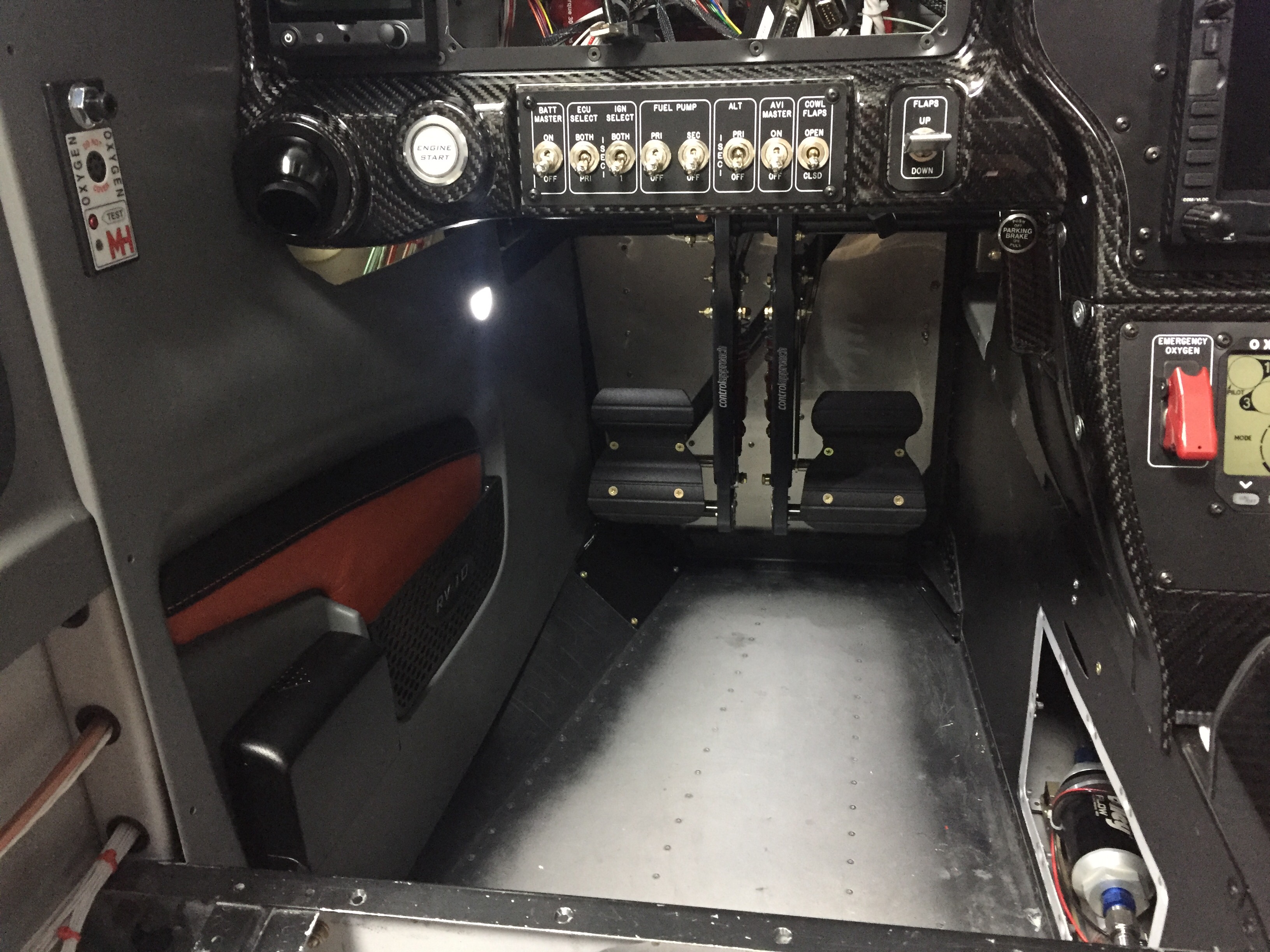
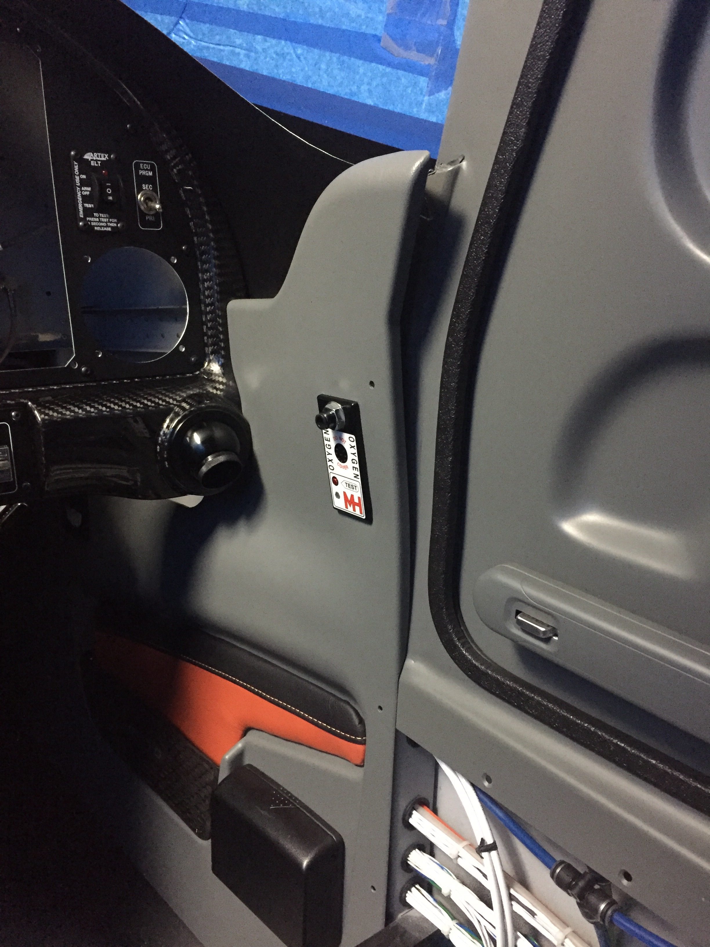
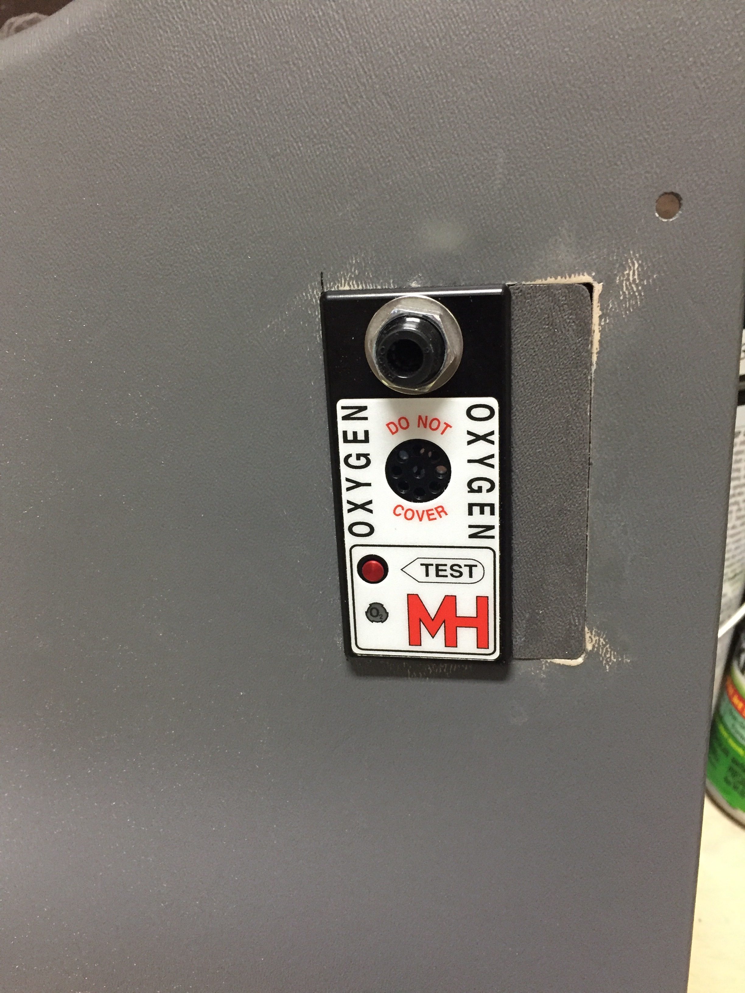
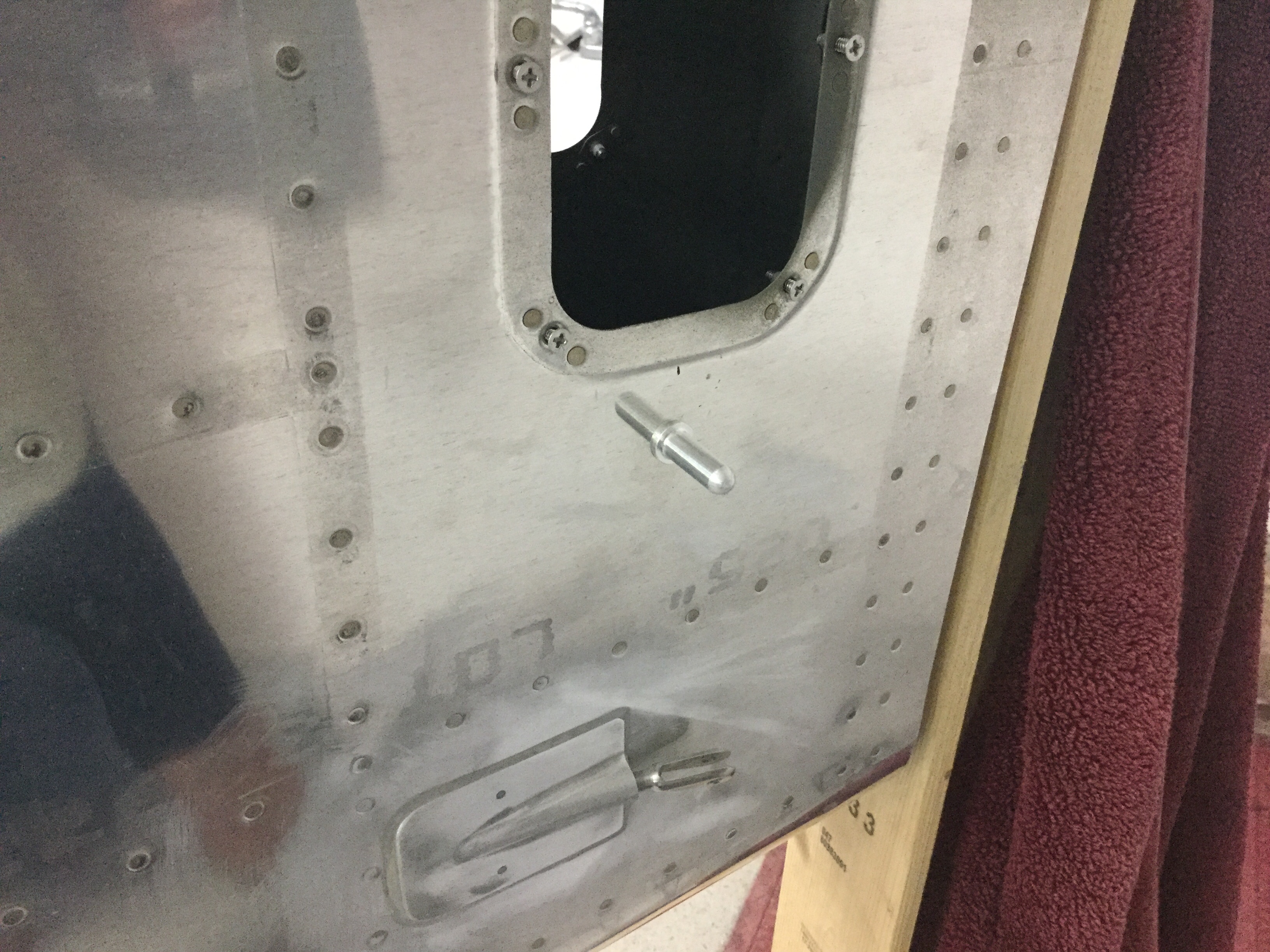
Unfortunately, not all of the gods were looking favorably upon this new addition and when I closed the door, the pins interfered with the oxygen ports, thus not allowing the doors to latch properly.  Turns out I have the ports ½” too close to the door frame.  Darn.  Well, I said, a lot more than that and maybe one or tools took flight across the garage with no lasting damage.  My blood pressure through the roof due to my ignorance and stupidity of not being mindful to this interference, I weighed the options of replacing $500 panels or coming up with a patch.  I can’t make the pins shorter since they wouldn’t function correctly with the Plane Around latch mechanism.  I had already had to glue a piece on the pilot side panel and reinforce it with a bit of epoxy.  The seam was easily hidden and paint covered everything, so I was hopeful I could repeat the process.  A call to Will at Aerosport Products equaled a few scrap pieces of plastic heading my way.  An evening of creating two patches and a bit of filler, and I’m back on track.  If you look close enough to tell the patch is there, you probably won’t be flying in my airplane again; kindly go away and take your judgement with you.

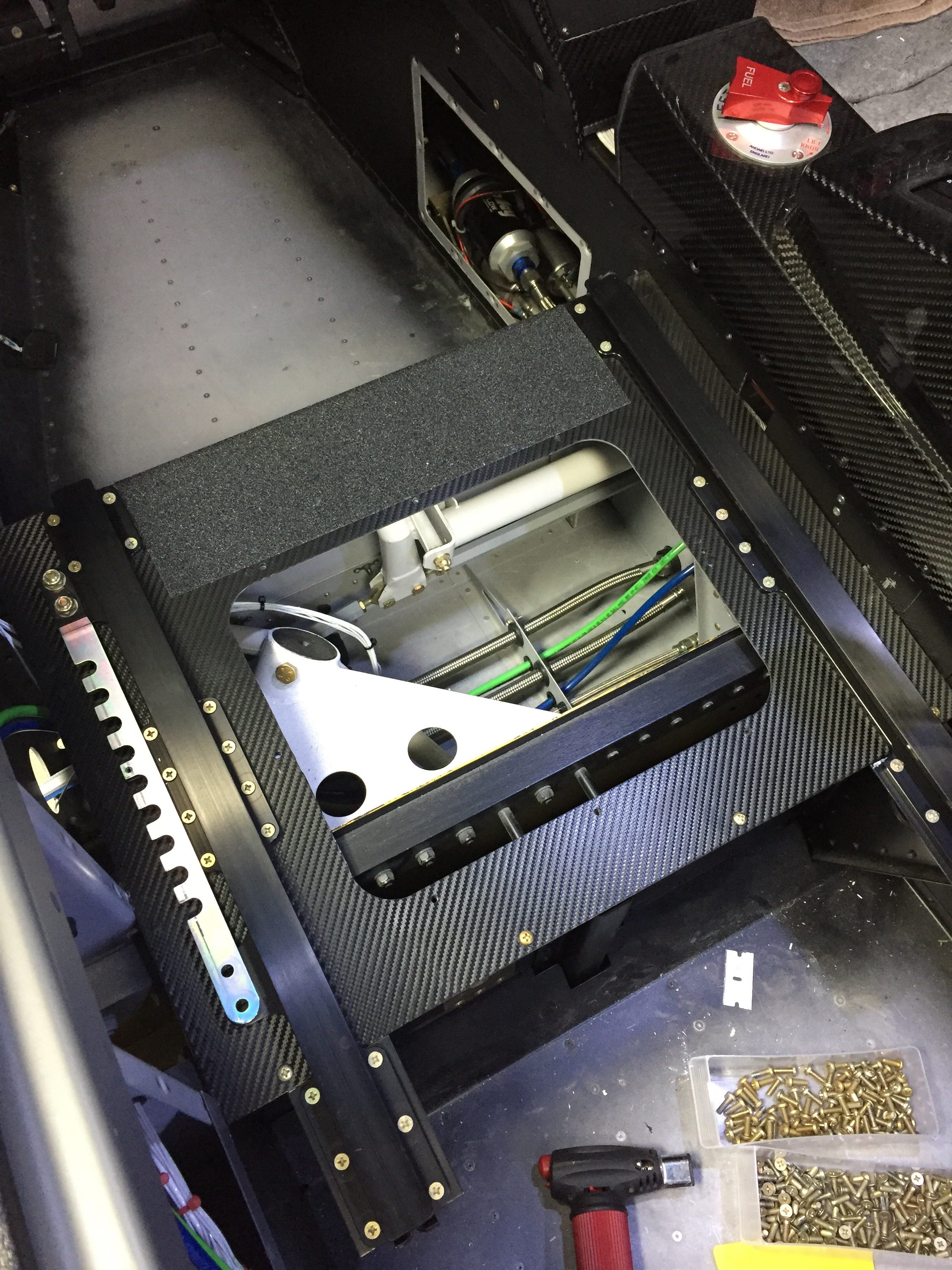
Meanwhile, I applied the 3M carbon vinyl wrap on the seat pans to clean those up.  I figured out quickly paint was not going to hold up there.  Brian and Brandi had great results with the wrap material, so I figured it’s worth a shot.  I then put a strip of anti-skid tape to facilitate stepping on the seat ledge while getting in and out.  It really cleaned up the area nicely.  I also shimmed the outboard pilot seat rail, as the bracket above the gear mount was a 1/8” proud causing the rail to bend when screwed in.  Not sure what happened there, but with a few washers underneath it’s nice and straight and secure.

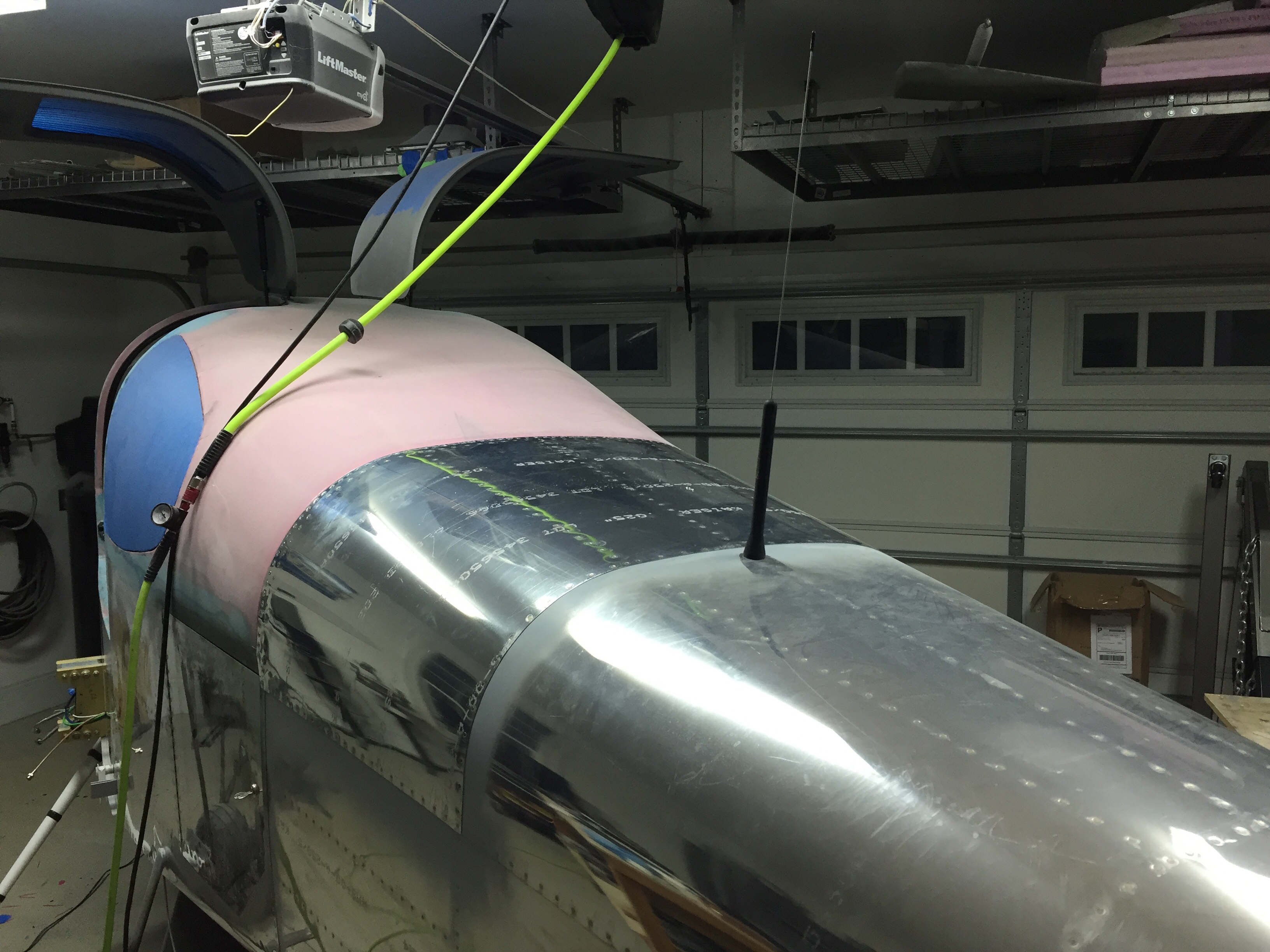
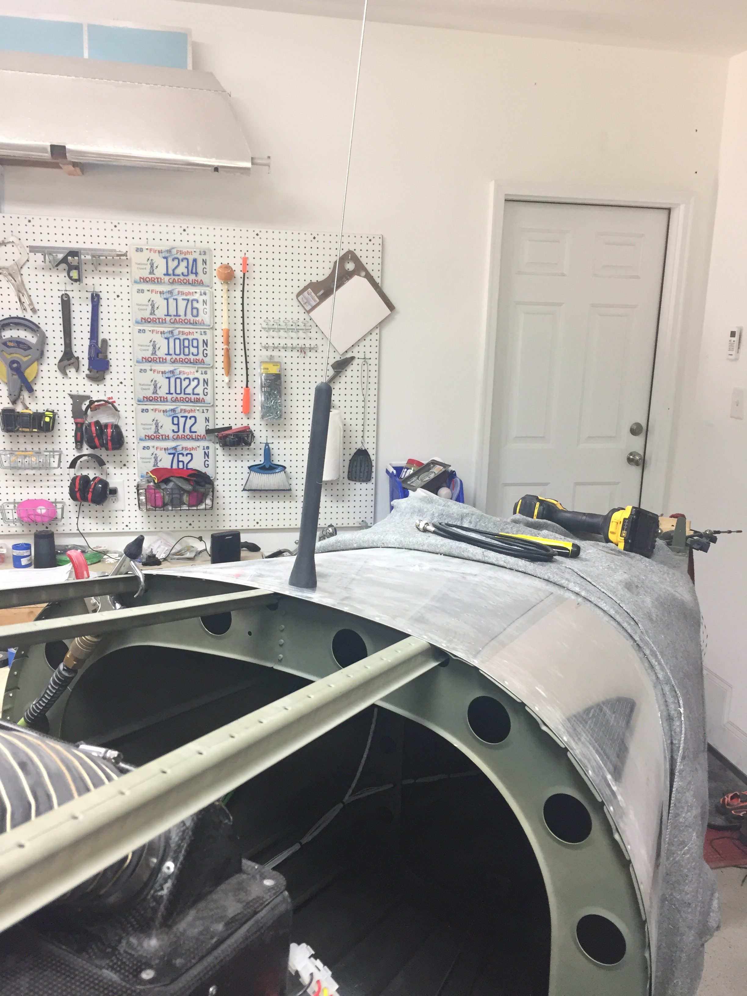
I quit trying to cheat the system and installed the ELT antenna on the top of the tail cone.  I tried every which way to hid that hideous monstrosity of an antenna but my conscious told me that it is probably the most important antenna on the airplane thus deserved its place per the install manual.  I’m sure it will grow on me.  The idea of burying it in the tail cone or tail fairing was tempting, but a talk with my DAR convinced me otherwise.

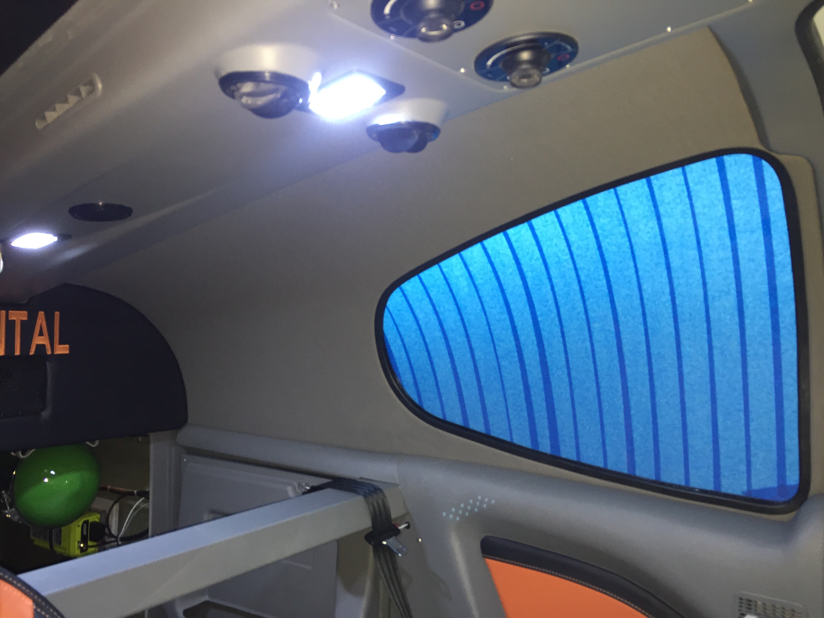
Continuing in the cabin, I spent an afternoon applying the headliner material to the fiberglass shells from Aerosport that had been trimmed for quite a while now.  It was a bit of a messy job with the spray adhesive, but not difficult at all.  I took my time and kept my fingers clean which resulted in a darn near perfect result.  After putting enough Velcro to hold a car upside down, the headliners slid into place and really dress up the cabin cover now.  The color matches great and was overall a lot easier than trying to smooth and paint the cabin top itself.

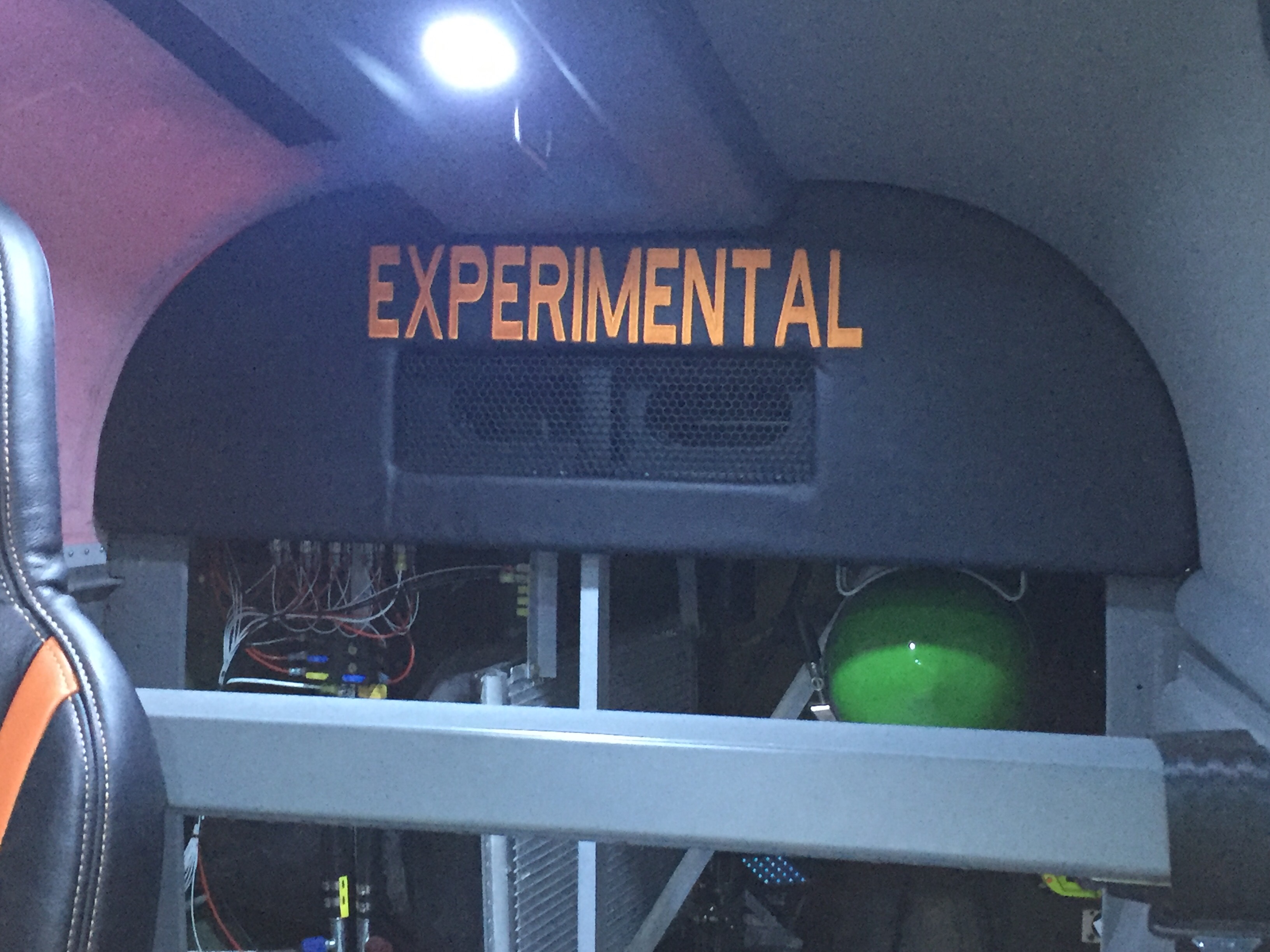
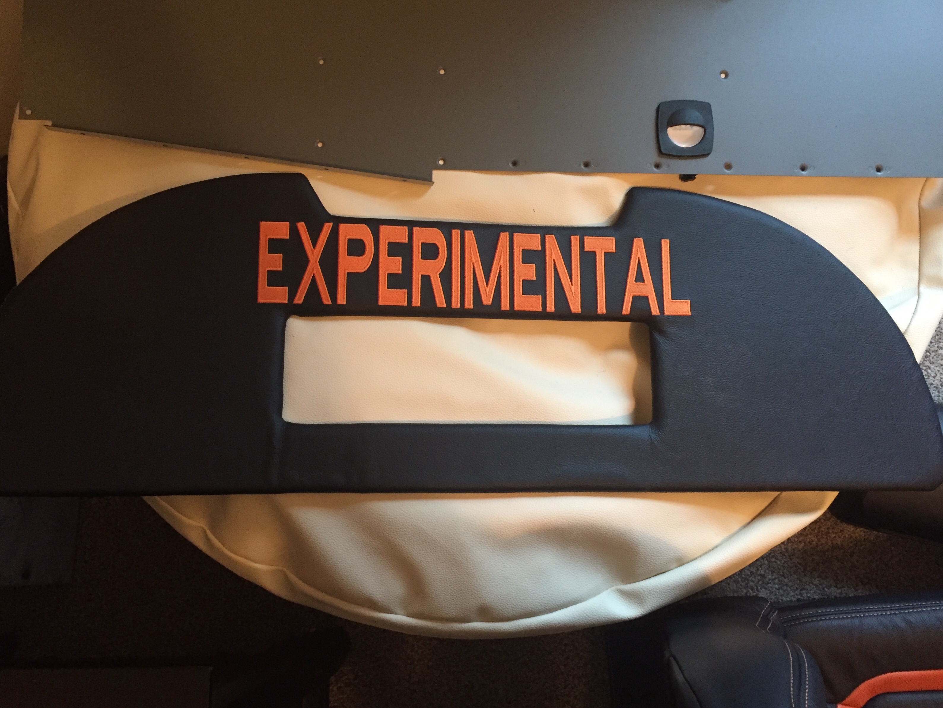
Finally, the rear bulkhead cover was back from Aerosport with the matching leather and embroidery.  I used Velcro to mount it to the bulkhead panel after installing a grill for the air conditioning return.  It turned out great and I’m really pleased with the fit and finish once it was all installed.  The cabin is really coming together with the rest of the rear side panels installed and inserts in place.  It’s tempting to put the carpet and seats in, but I’m holding off to keep them in good shape and clean while I finish building.

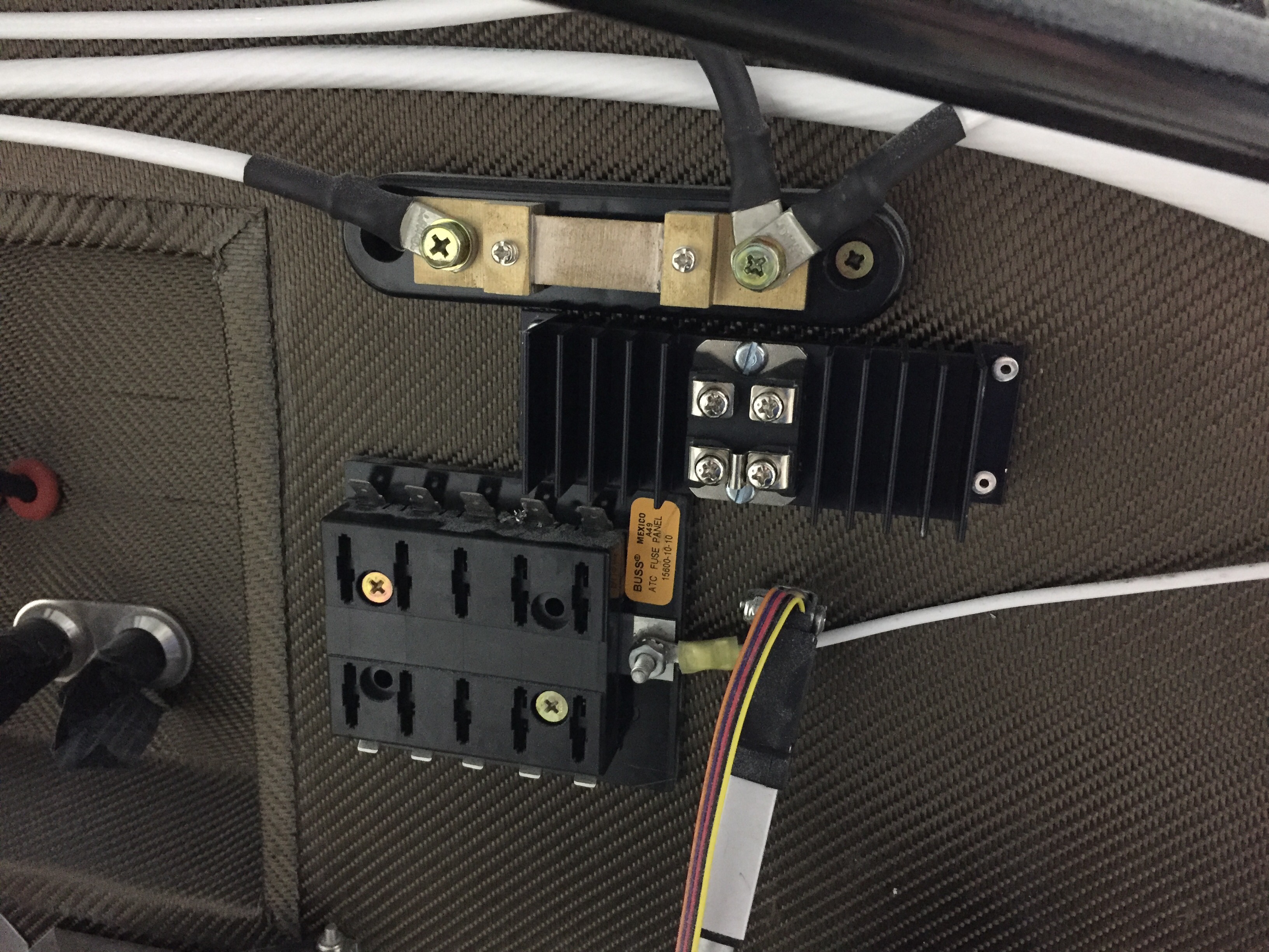
Upfront, I had an epiphany about my shotky diode and how it should be used to protect my engine bus.  The goal was to isolate the engine bus from the rest of the system such that I can turn the emergency power switch on (direct connection from battery to engine bus) and not have the electrons go to the man bus.  This essentially covers a short somewhere in the system or electrical fire behind the panel and gives me a bit of redundancy on keeping the electrically dependent engine going.  I wasn’t placing it on the proper power lead on the schematic, so it finally dawned on me it should go from the main power supply instead of the backup lead.  So, I installed it on the firewall and will work on a solid copper bar to hook everything up.

Garlic Sauce and Grape Jelly – Building an Airplane Engine

Fair warning, there are lots of pictures in this post!

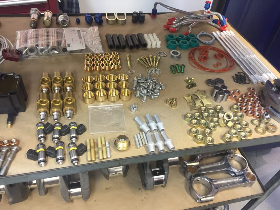
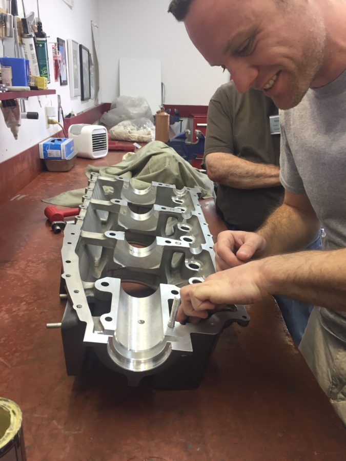
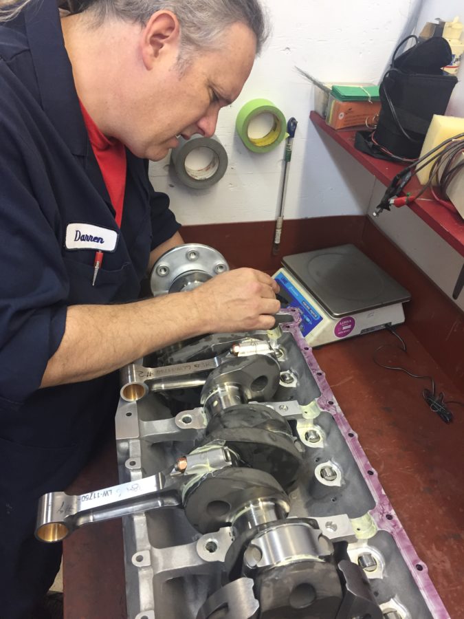
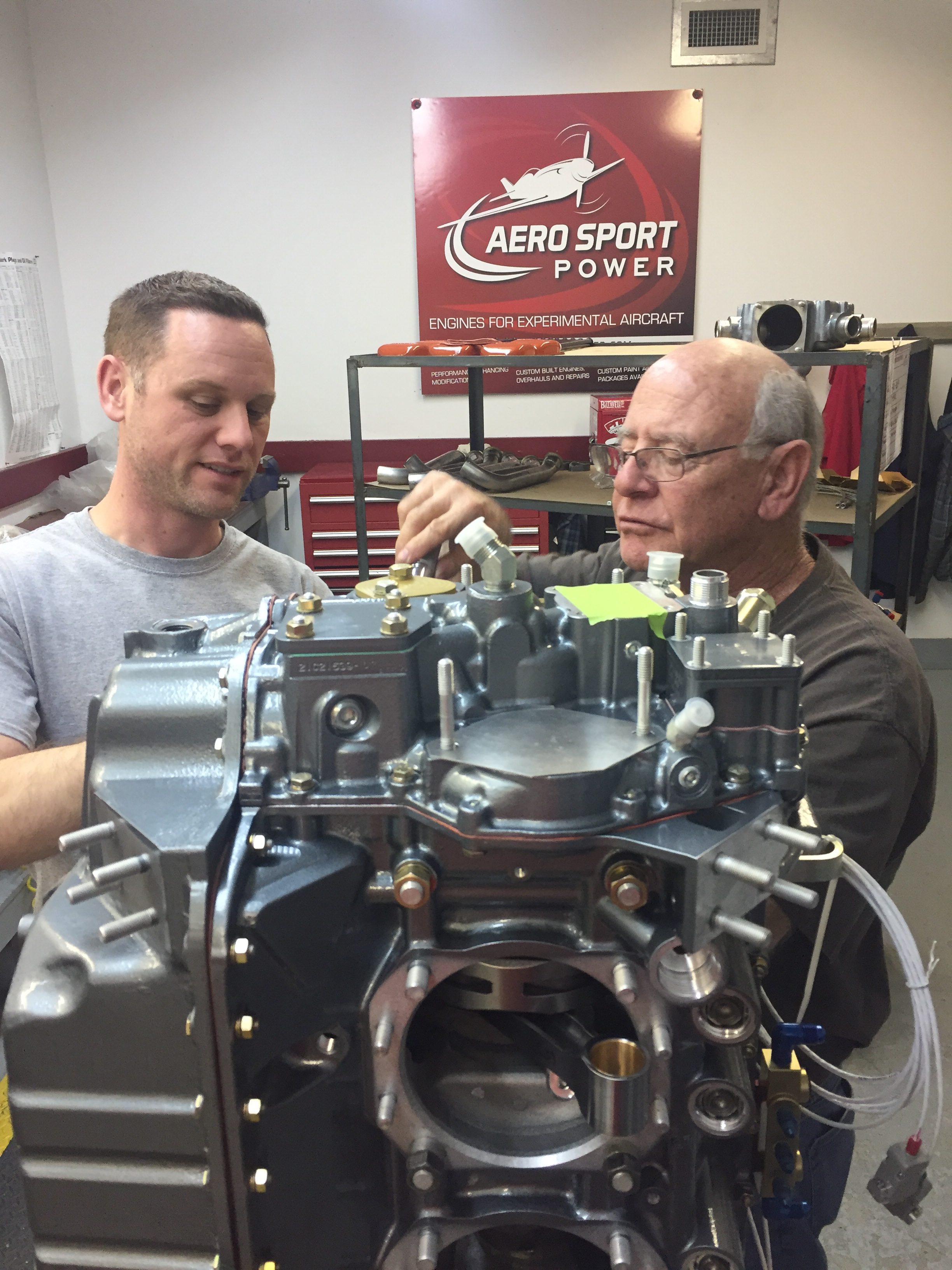
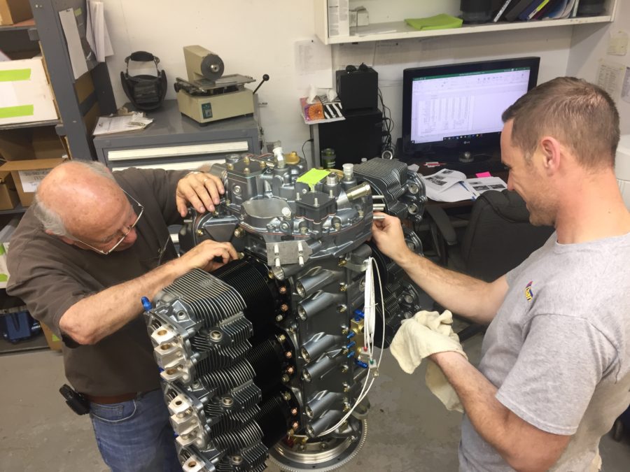
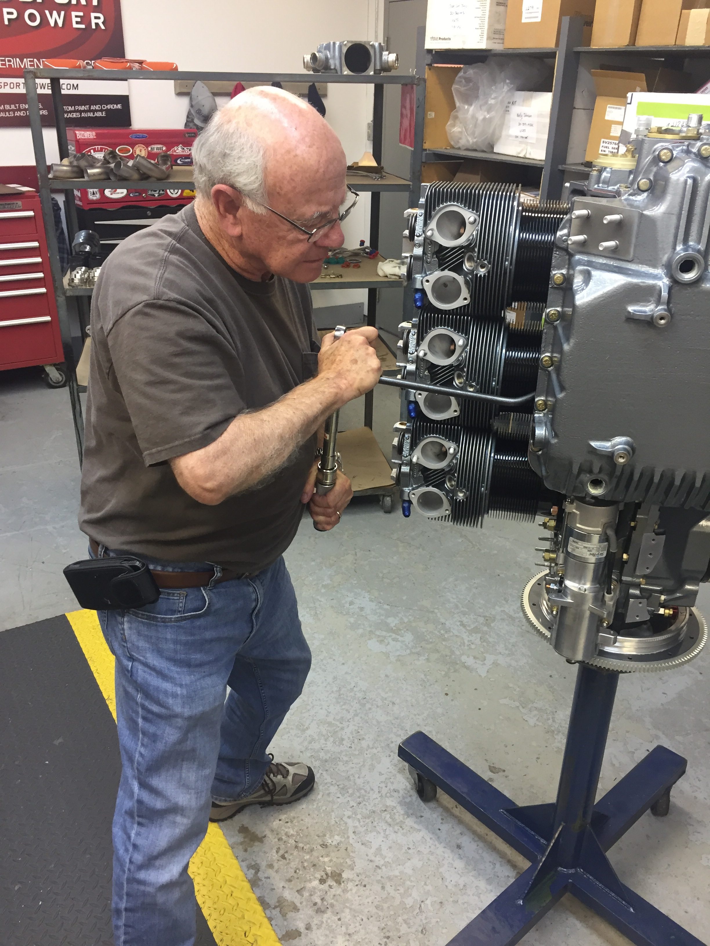
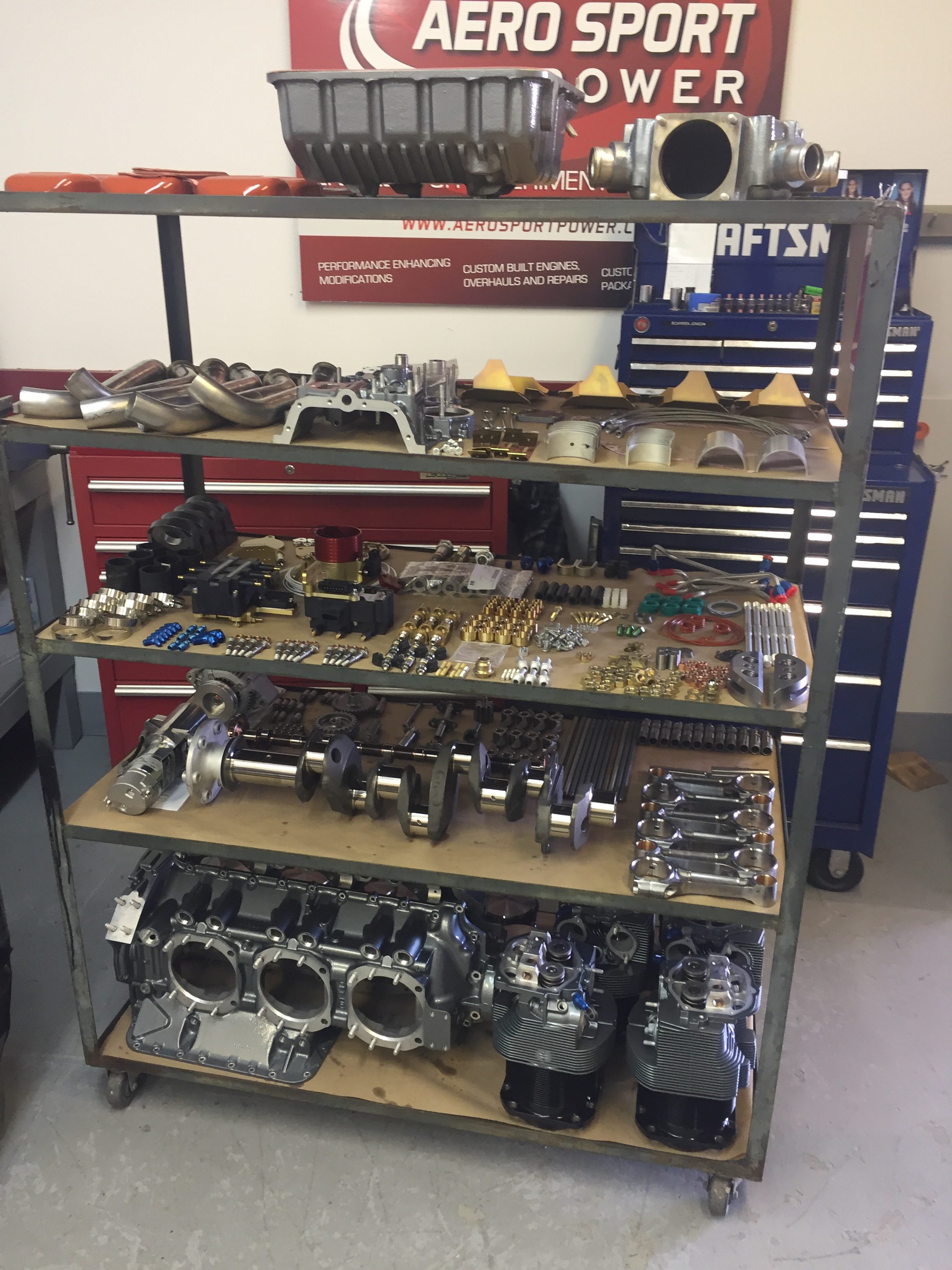
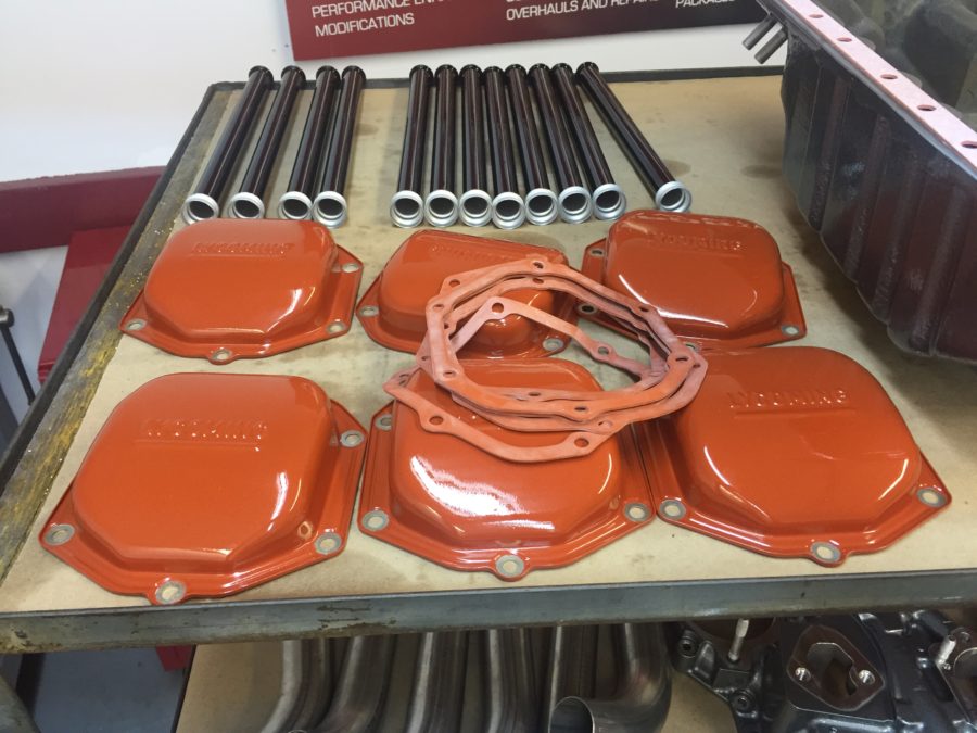
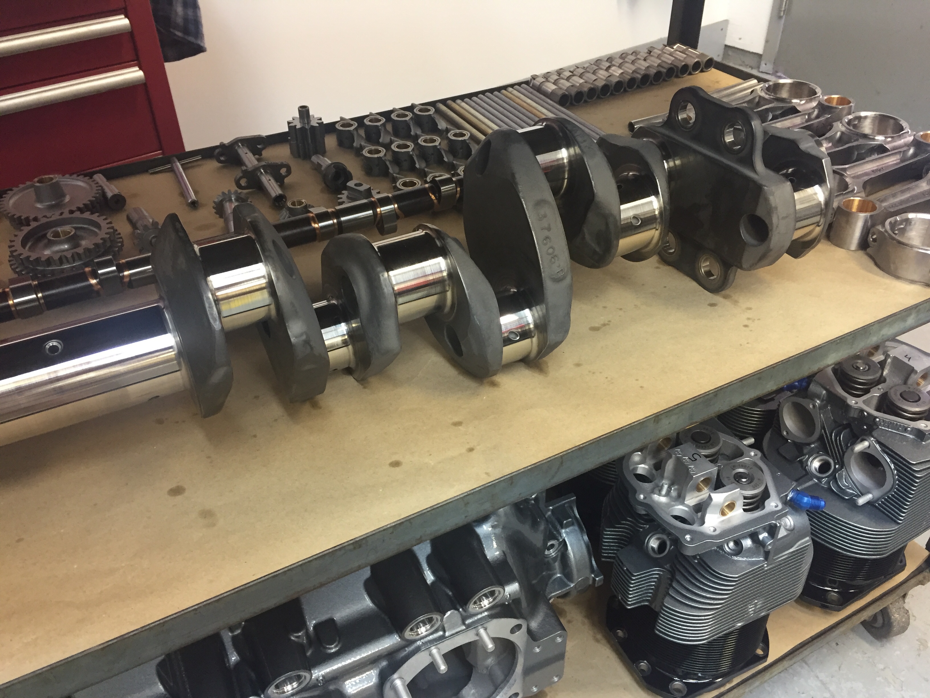
My dad and I were pretty darned excited (okay my dad was REALLY excited) about spending time together building my engine. We arrived at Aero Sport Tuesday morning with donuts and were instantly welcomed as family. Maybe it was the donuts, maybe it was my dad’s flirting with the receptionist. I don’t know, but it worked. We were in. Darren turned out to be our build guy so I really had a complete experience with him and couldn’t have asked for a better mentor. He showed us the whole shop, introduced us to folks and explained some of their equipment. We made it to a back assembly room where a cart sat containing all (most) of the parts for my engine – painted, prepped, and organized. We wasted no time and dove in starting with rods on the crankshaft. Darren let dad and I do pretty much everything with a sharp eye on us over our shoulders. This is exactly what we wanted, but we learned other folks may just want to sit back and watch a master at work which is just fine too.

One thing we quickly learned was how to properly lubricate EVERYTHING in the engine. Even bolts that were getting torqued were lubricated, something I had never heard of. The Lubriplate mixed with a little STP oil turned out looking like garlic sauce from Papa Johns and we put that crap on everything, just like you would with pizza. It protects the components during assembly, keeps oxygen and therefore rust at bay until operation, and lubricates the workings of the engine during first start until oil has really gotten everywhere. Our IPI (in process inspections) were completed by Darren as he double checked our torque values and work before proceeding on. It was apparent that Darren had done this before as proven when he picked up a journal bearing and by feel recognized the parts man had pulled the wrong part number. He gave us a task and ran off to the parts counter a few rooms over to retrieve the proper items. This happened a few times and showed that they are still improving their processes but highlighted the incredible amount of experience and knowledge all the employees there have about building engines.

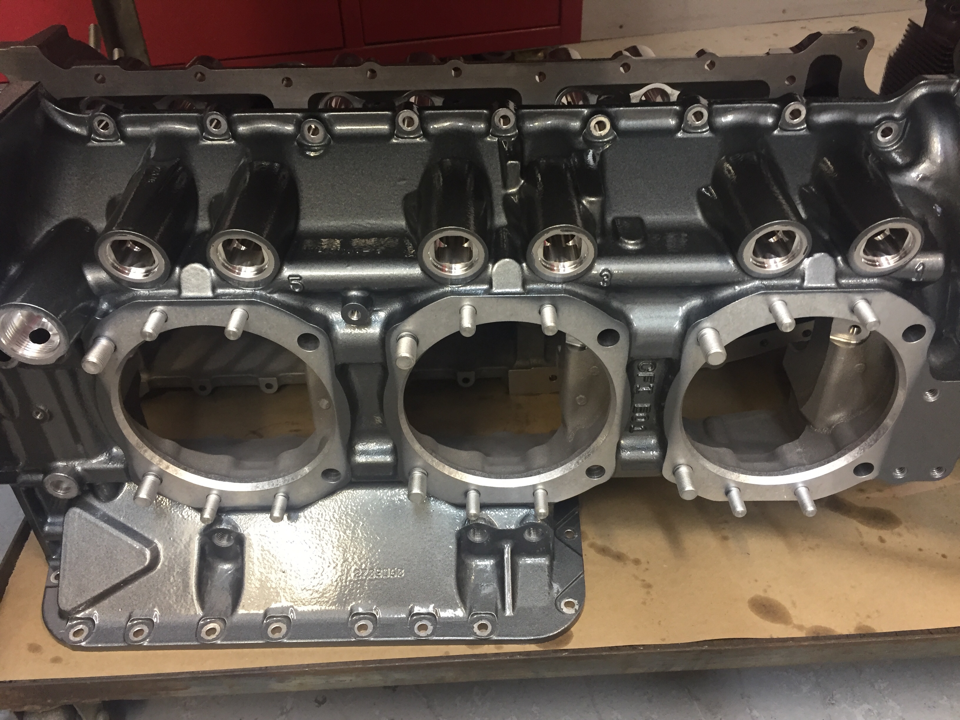
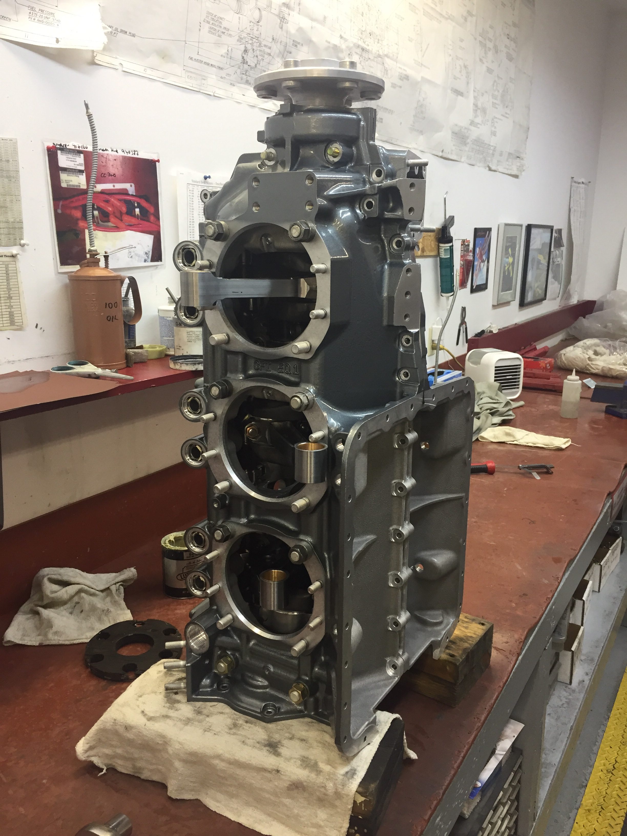
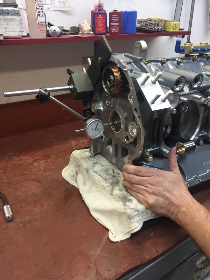
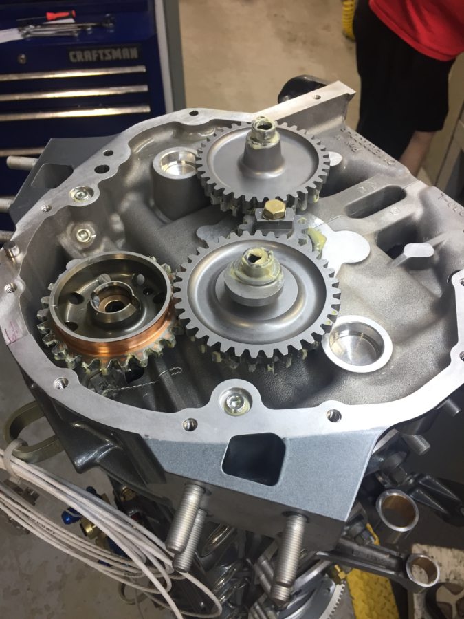
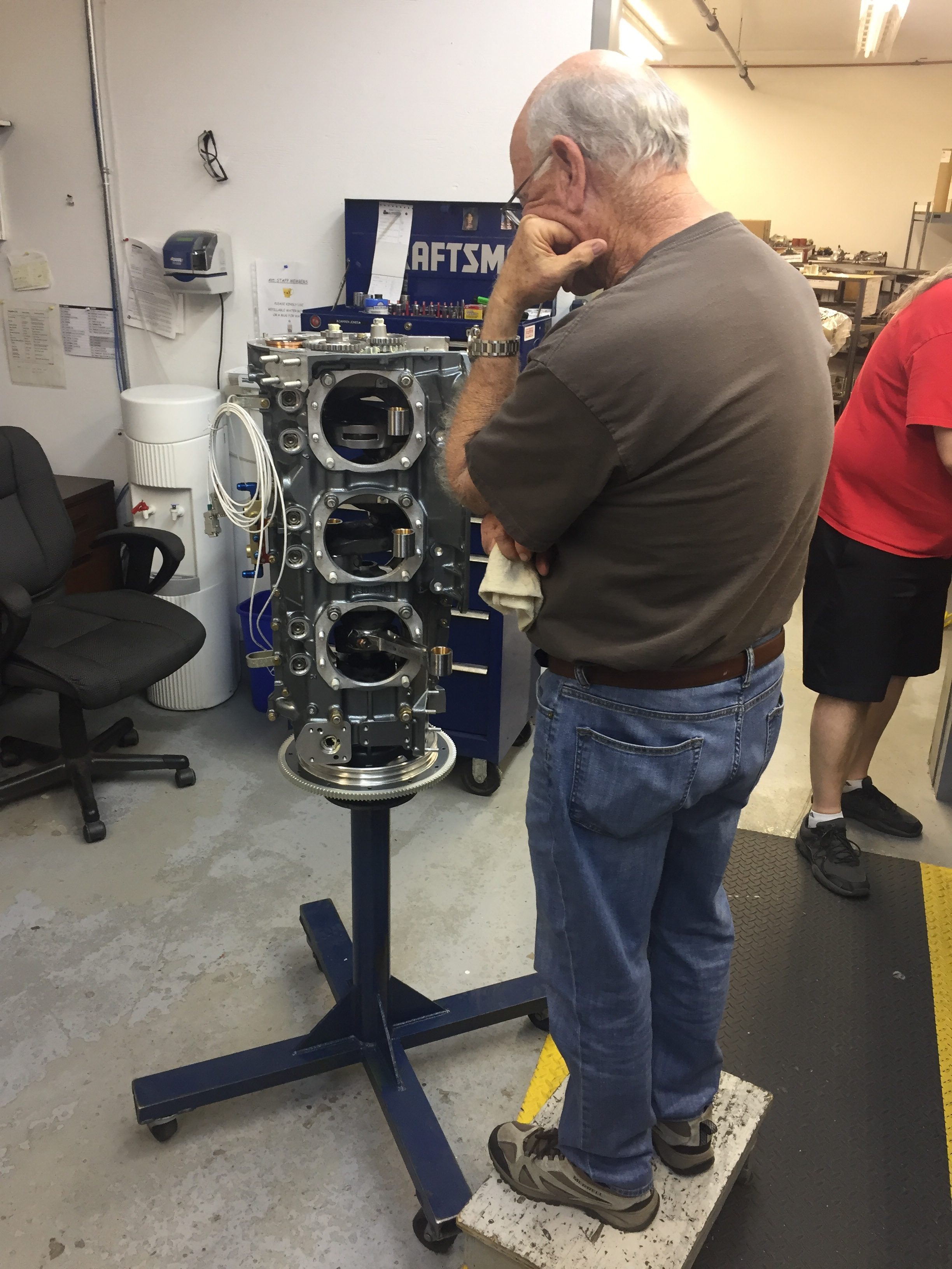
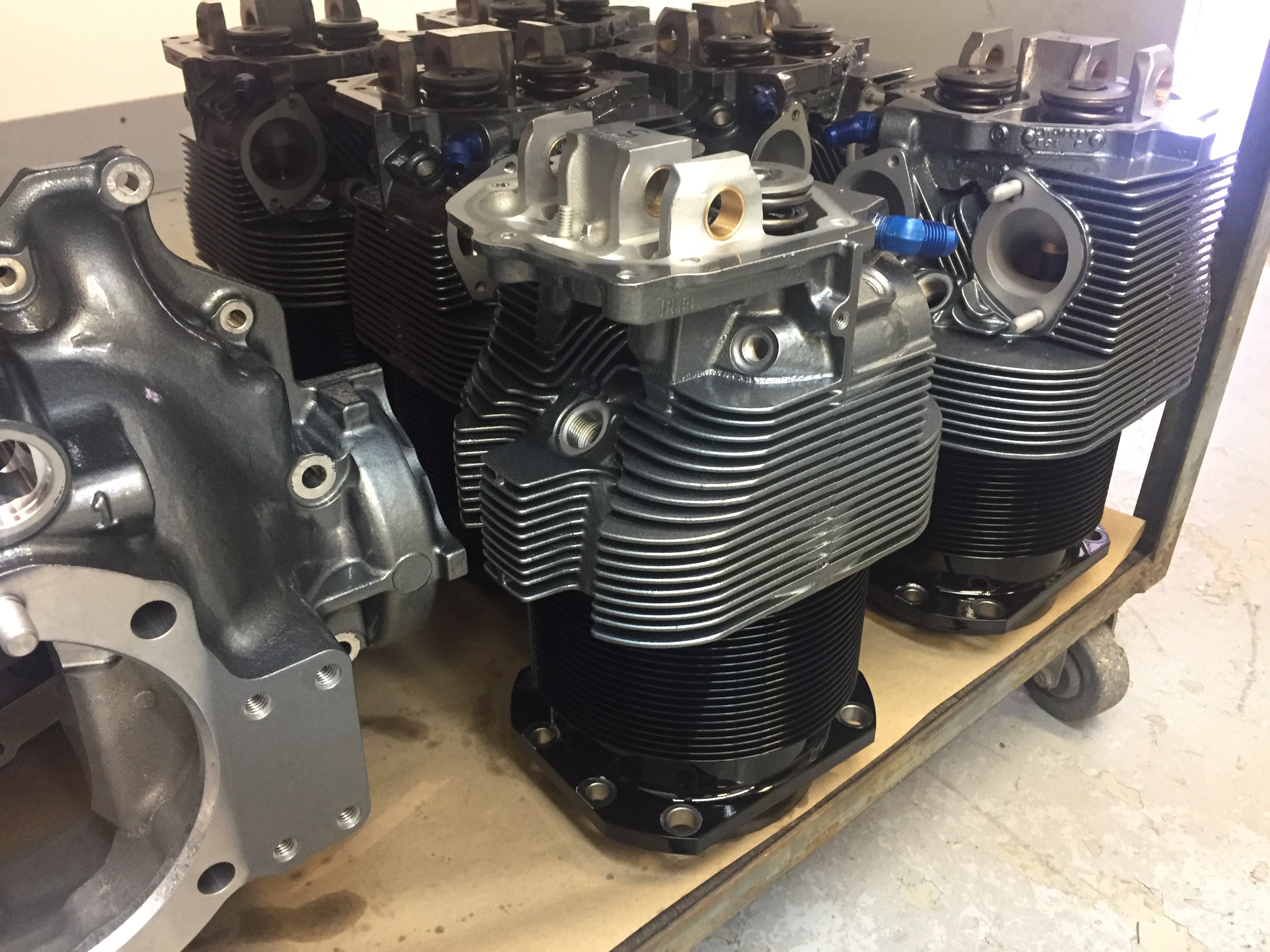
The crankshaft monster quickly grew with rods and pistons before the case halves went on with journal bearings and a few accessories followed by the cylinders. It’s a lot of work, but it’s remarkably simple with pretty loose tolerances hence the inherent inefficiencies compared to a modern car engine let’s say. Lycomings have been around for a long damn time and not much has changed in the design even if manufacturing tolerances have been vastly improved. By the end of the day, we had what pretty much resembled an airplane engine including the accessory case on, for the first time at least. While putting on the cold air induction, we had a fit issue with the oil screen that was immediately handled by the machine shop who bored out a recess. The right tools make any job simple. That and having the right people who know what they hell they are doing. I sometimes think I should not own a Dremel, as I think I can CNC machine things freehand.

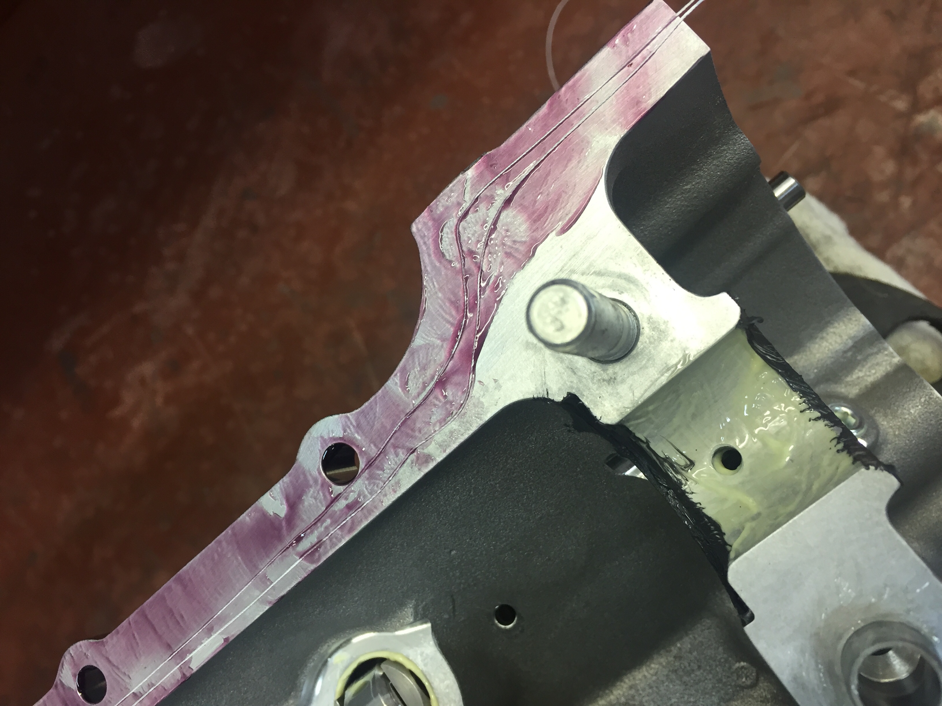
Day two started off with a Knock It Off, as we say in the Air Force. Darren wasn’t happy with having the tach drive shaft removed since it would create a leak point on the accessory gear case and be hard to seal. Even though I don’t need the tach drive and it meant pulling the sealed/gasket-ed case off, we did the right thing and removed it. The shaft adds a few ounces but can be left unattached to anything and is now properly sealed with the bearing and oil seal. We made the quick fix and all agreed we felt better. Dad even got to play with the Loctite that resembles grape jelly in looks but not taste. This is special gasket gel that only cures in the absence of oxygen. So it forms a rock solid gasket but any excess that oozes into the internal workings of the engine won’t cause any issues before it gets caught by the filter.

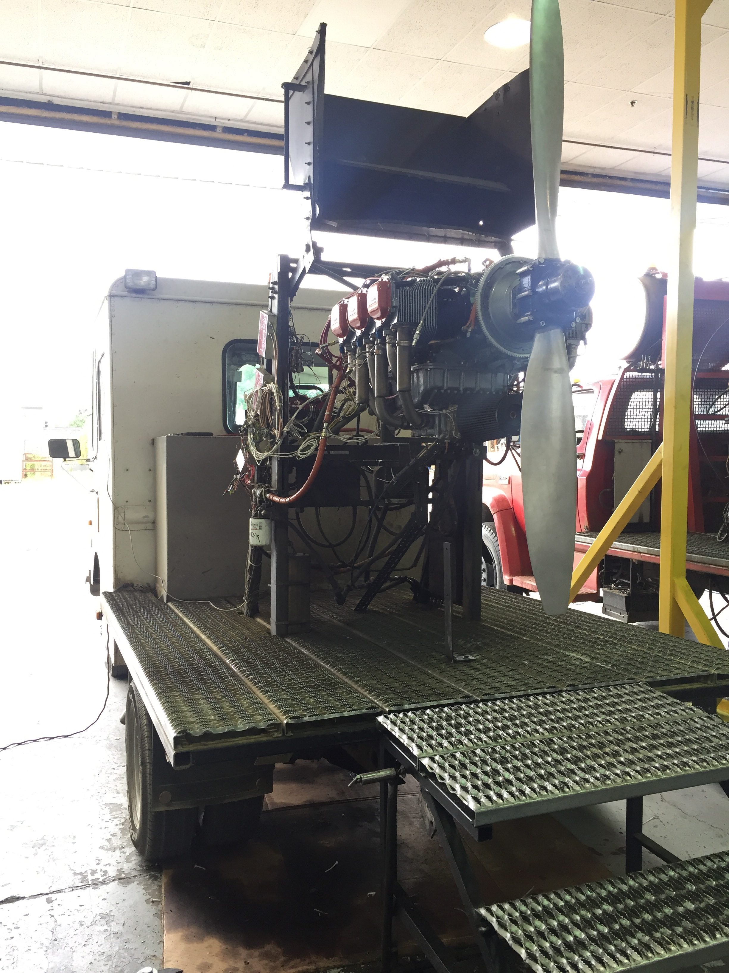
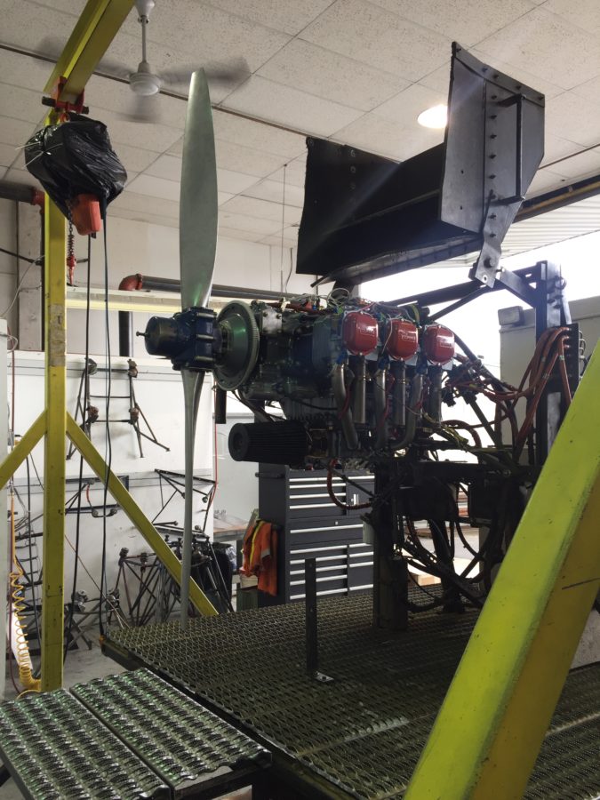
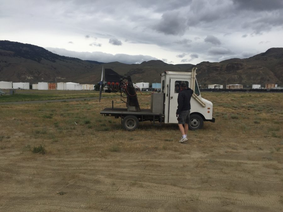
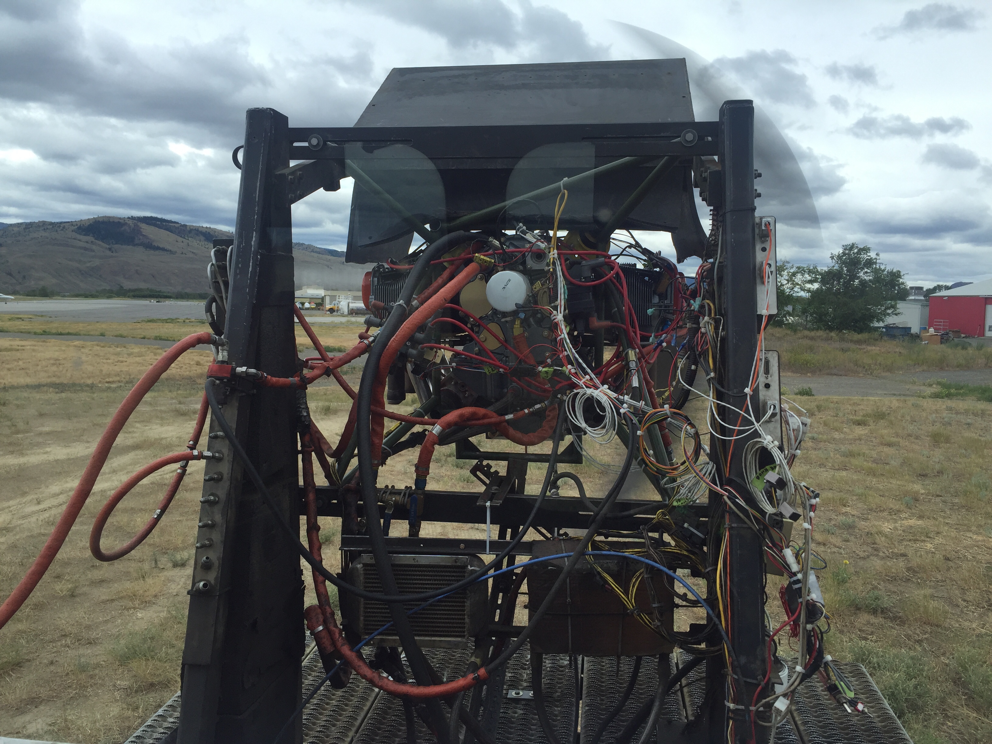
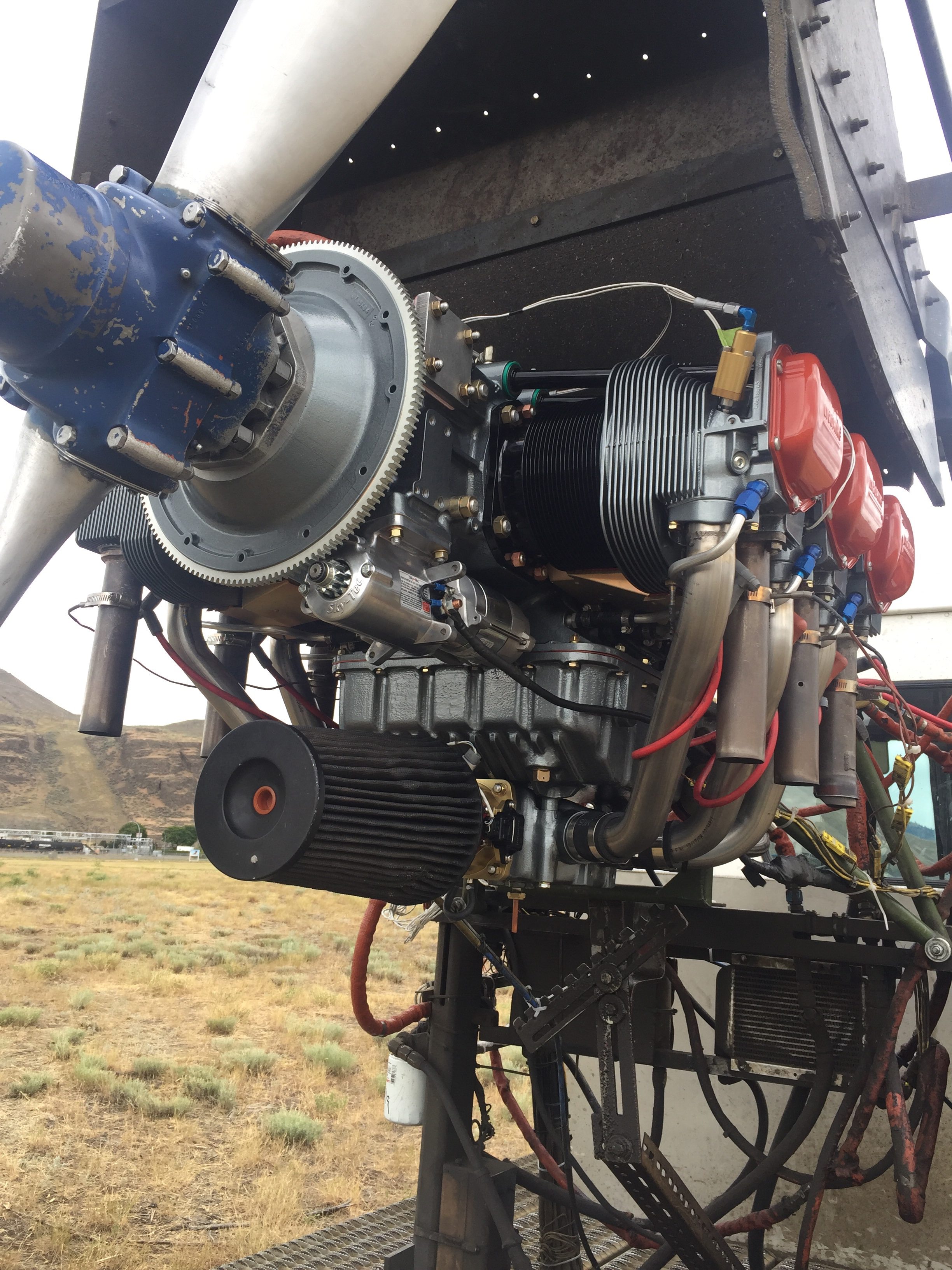
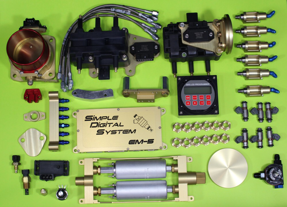
We fit the push rods and rockers in the heads and learned how to properly gap the valves along with a few neat tricks with safety wire that I have taken back home to others. Other than a crazy push rod that we suspect was cut and not remarked, it all went really smoothly and by lunch the cart of parts was just a lonely empty cart! After lunch, we bolted on a few SDS accessories to shift from building to prepping for first start. Dad and I took the afternoon off while the test department hung the engine onto the Test rig which looks like an old bread truck of some kind.  I can only imagine the number of hours that thing has racked up going from their hangar to the field at the end of the runway about 1000 yards away.  They are no stranger to various engine configurations and had the sensor and control package hooked up quickly.  An old prop was bolted on and ground adjusted to that looks about right and she was ready for the next morning.

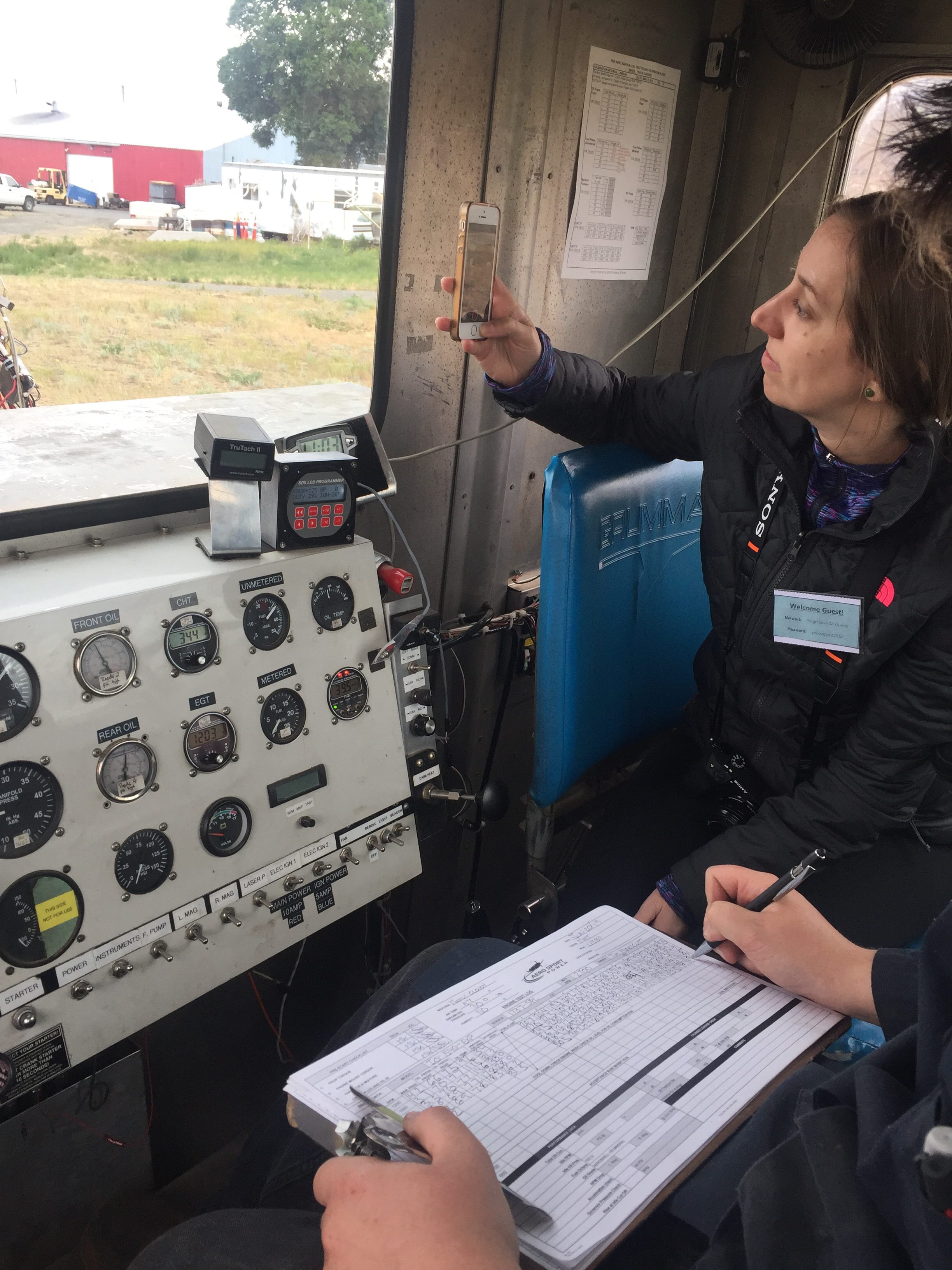
We awoke the next morning to a blustery wind bringing a chill from the mountains across the plains of western Canada.  Oh wait, this isn’t a novel.  It was freaking cold and drizzling the final morning but we braved the elements and watched the guys pre-oil the engine.  Finally, it was time to burn some avgas so we followed the truck out to the field and held our breath as the tech turned the start key for the first time.  We were warned it may not start the first time but I wasn’t too concerned about that.  Sure enough, the second start attempt resulted in a few puffs of white smoke and a low rumble of our engine running for the first time!  Lots of smiles and hugs and handshakes all around, it really was an awesome sight and sound to see something that we put so much work into start up and run like a champ.  Dad and I built an engine (with a bit of help from Darren) and it’s alive!

Laura and I hopped in the truck and got to see a bit of the magic behind the scenes as they ran through the initial checks.  Aero Sport does a few hours of running total to start the shake down and break in process.  On each subsequent start, the engine fired off within a blade or two and only minor mixture (via the SDS knob) were made to keep temps under control.  The tech said that’s typical with the rough cut universal baffle setup they have on the truck.  As exciting as it was to see it run, we were hungry and cold, so let the pros finish up with the run time and headed inside to talk with Doug about some tips for our first start and break in. 

Running the engine at high power setting and avoid ground running was the biggest piece of advice given.  A few other notes about power and rpm along with oil changes and temperature expectations were good information to have and a lot to take in.  Meanwhile, the engine was removed from the test truck and had a complete checkout including draining the oil and checking the filter – no metal!  All of our garlic sauce and grape jelly did its job.  The tech will finish bolting the accessories on and preserve it for the few more months until we are ready to start it and go flying.

All too soon, it was time to say our goodbyes to the amazing team at Aero Sport Power.  We really felt like family there after three short days and genuinely feel welcomed back at any time.  I’m really excited to have the hands on experience of building my own engine and getting an understanding of how it is assembled and operates.  It was some great father-son time as well and the memories will last long beyond first overhaul!

Random pictures:

Let’s build an engine, eh?

Perhaps the biggest and most expensive decision in building a plane is what engine will be powering the hopes and dreams of the builder while turning many dollars of avgas into adventures.  Some may know that I’ve been involved with an alternate engine that has unfortunately not matured enough to be on my plane just yet.  I’ll detail that in a future post, but this one is all about the Lycoming!

The backstory to what impacted my decisions stems from my flying experience, goals and missions for our plane, and personal preference.  I knew that I wanted to start off with a completely new engine, no overhauled components.  That is not to say an overhauled or even factory 0 time (but not new) engine isn’t as good as being brand new.  I just want a fresh start and a foundation that I could overhaul in the future.  I also want an engine that is efficient and powerful.  I’m not interested in exceeding Vne or supercharging the thing to 1000 horsepower, but I do want something a little hot rodded above the stock 260 horsepower of an IO-540.  I also want it efficient, not only for mission range and cost, but to be somewhat green and environmentally friendly.  Afterall, trees need hugs too, right?  Most importantly, however, I wanted to have a modern engine or at least as modern as you can with a 1930’s tractor inspired design.  That meant electronic gizmos and a lot of them!

While researching new engines, the usual suppliers popped up.  Van’s will sell a crate engine with few if no modifications or choices available.  Lycoming will sell directly through Thunderbolt lines with some options available and even paint the engine a custom color as long as that color is red!  Barret Precision Engines can get a new crate engine or overhaul a used core to build essentially anything you want.  Lycon will put 54 to 1 compression pistons that require nuclear fuel to run and charge you the equivalent fee for it.  Numerous local shops can build from parts or rebuild a core engine.  Or you can simply purchase a running engine from a sellar and slap it on the plane.  For me, it came down to two vendors, Barret and Aero Sport Power.

Aero Sport Power is in Kamloops, BC and has been building experimental and certified engines for decades.  They have a great reputation with the aerobatic folks and have an entire business division to cater soley towards ameature built aircraft engines.  They also have a unique offering, a build school that is a three day course where you get to participate as much or little as desired in the build of your engine capped off with a first start and test run on their test stand.  Darren is a phenominal resource and will hand walk you through everything from figuring out which engine you actually need (IO-540-R2D2 hah!) all the way to which hotel is best to stay at in BC and how to run your new engine during the first few flights.  What I liked about Aero Sport the most is technical:  they are an authorized Lycoming builder that can order a new engine kit unassembled.  What that means is they build the engine to my specs, not take a crate engine and rip components off to replace with aftermarket upgrades.

So I called Darren and started talking about what I wanted.  Lycoming 540 with 9:1 compression, SDS dual ECU injection and ignition, BPE cold air induction, no mechanical fuel pump (not needed with SDS) dual groove flywheel for aircon, remote oil filter, 70 amp alternator with 30 amp back up, and of course custom paint scheme.  This all was an easy kill for Aero Sport who promptly gave me a quote and lead time.  They then put up with me asking questions, requesting information, putting the purchase off, and finally committing in January of this year with a July build date.  The price wasn’t the cheapest, but it also wasn’t the most expensive, apples to apples.  They were, though, the only shop who could build (not re-build) the exact engine I wanted.  The icing on the cake was the chance to come up and help build it! This is how excited I was!

With the deposit paid, planning began on keeping the copilot happy by having a vacation in conjunction with the build class.  We worked out flying into Calgary and taking our time traveling west over the mountains to Banff then to Kamloops before spending a few days backpack camping back in Yoho then flying home.  To top it off, my dad and step mom had a similar idea, taking a cross country train from Toronto to Vancouver then meeting us in Kamloops so pops and I could build the engine father/son.  I won’t get into all of the vacation details, but we now have free tickets from American thanks to our luggage traveling halfway around the country before making it to our hands on day three of the trip.  We traded the backpack camping for day hiking and an Air BnB with a hot tub due to snow and head colds and came home happy!

The summary for builders is take a lot of time and research the build shop you want.  Build the engine like you build your plane, just the way you want it.  Need to save money?  Do it.  Want the bling?  Chrome everything.  More power?  Do it.  Your life and the lives of your passengers depend on your powerplant more than any other component so make sure you are comfortable with your engine and are happy with your decision.  I’d be happy to talk with anyone about the finances and other small decisions to help a fellow builder.

Stay tuned for the build school write up.

Punching the punch list

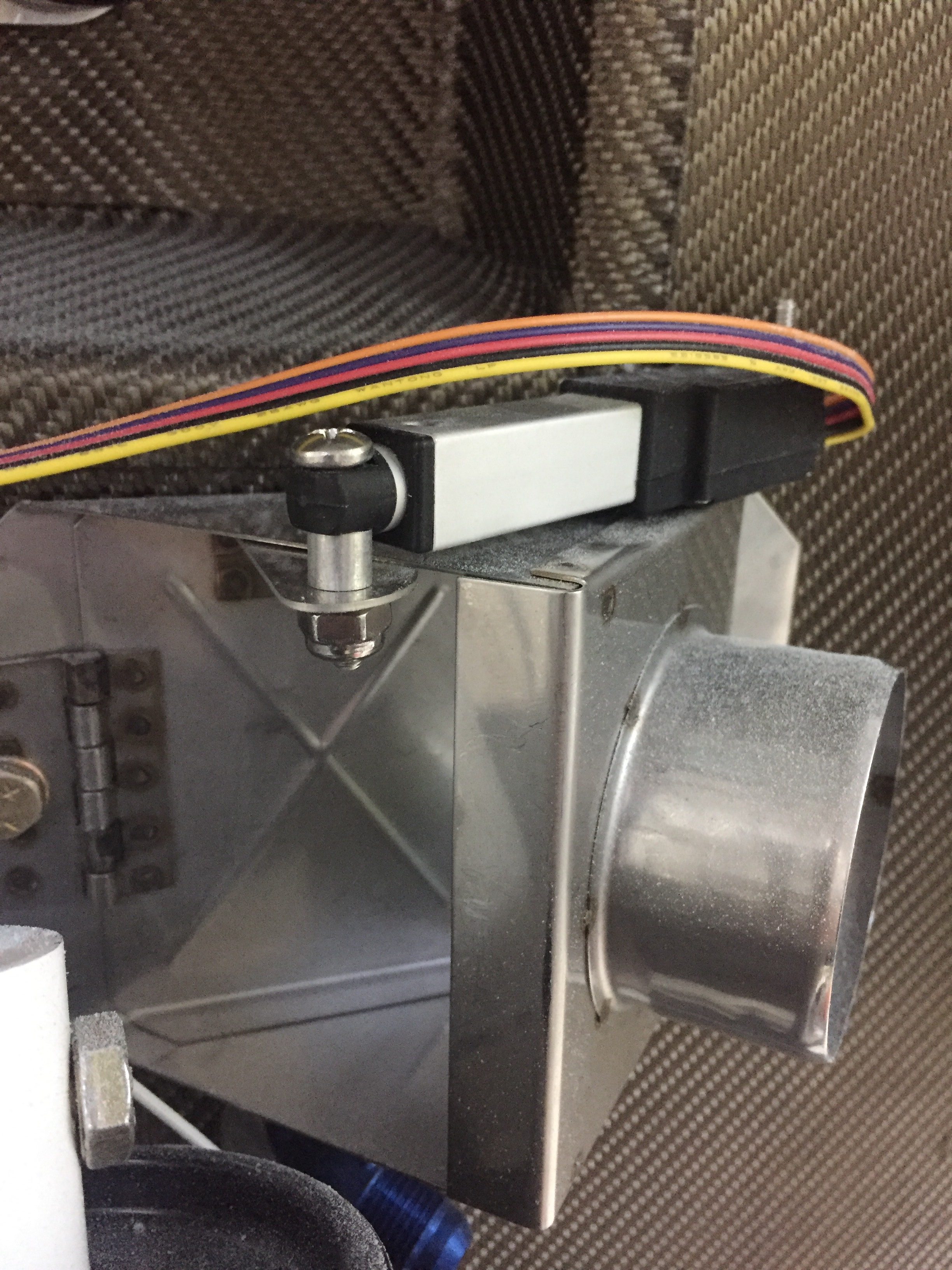
There are a lot of little jobs that go along with the big jobs on building a plane.  I’m trying to use my time efficiently while waiting on the engine to knock out a bunch of them.  The first was fixing the arms and servos on the heat ducts up front.  An order to ACS and a few minutes at the band saw and the servos for the heat and oil coolers were attached properly and pots adjusted for full travel.  I also spent an hour trouble shooting a bad pot for the rear heat duct, as I have a switch that allows either the front or rear rheostats to control the servo and the rear rheostat was inop.

I cussed and bled in equal amounts installing the last of the seat rail brackets now the gears are on.  The nuts and bolts are not easy to access at this point, but you have to wait in order to install the gear bolt.  I also put in the last bolt and custom spacer for the GPU plug which helps reinforce the receptacle by attaching it to the seat pan.

I ignorantly forgot to install the transponder antenna before buttoning up the tunnel, so I had to take the center console, tunnel cover, and lower instrument panel off to get down in there.  Of course I burried it near the core of the earth which made access tricky to say the least.  I was able to squeez my hands down there and got it all bolted on with the coax attached.  I knew I had left one fuel line untorqued but couldn’t remember which one so checked all fuel line fittings for proper torque.

The last task in the rear tunnel is to secure the aircon lines which I did with some hose clamps and edge grommet material.  Again, not fun to get to the hardware but it was doable and will rarely if ever be removed.  The lines are now secure and fit nicely in the tunnel, I’m glad I didn’t run them down the side of the fuse.  I also secured the last little sections of the O2 lines in the tunnel.

My ELT antenna placement has been a topic of disagreement on VAF, as I really wanted to avoid mounting it on top of the tail cone.  It’s big, ugly, and ugly.  Mainly, though, it’s ugly.  It’s also essential to my life and the lives of my passengers should the worst happen and we have an accident, so I guess it’s important to do it right.  I debated on doing some reception tests with it mounted internal to the tail cone, but honestly, I just got lazy and decided it really isn’t that ugly.  In the end, I chose to do it the right way and put it on the top of the tail cone.  The cable was secured along a bulkhead and the last of the wiring clean up for the O2 tank / ELT was completed.

I love spending time wiggling back into the tail coffin, I mean cone, so I made a fort with blankets and towels and dove in to attach the OAT sensors to the ADAHRS and finish securing tail cone wiring.  I put the OAT sensors below the access panels underneath the horizontal stab since I had all of my wing wiring complete and for shorter wire runs to the ADAHRS.  Since they have to be calibrated anyway, I’m not too concerned with exhaust from the engine affecting them too much.

The O2 tank was put back in for good and connected to all of the lines.  I also attached the pitch auto pilot servo to the bellcrank and will connect the yaw servo once the tail feathers and rudder cables are rigged at the hangar.  That is the last task in the tail cone and can be completed without having to crawl all the way back there.  It’s going to be motivation in life to keep from getting fat or have a small child that can slide back there for maintenance, it’s a very tight fit with all the extra stuff I put back there.

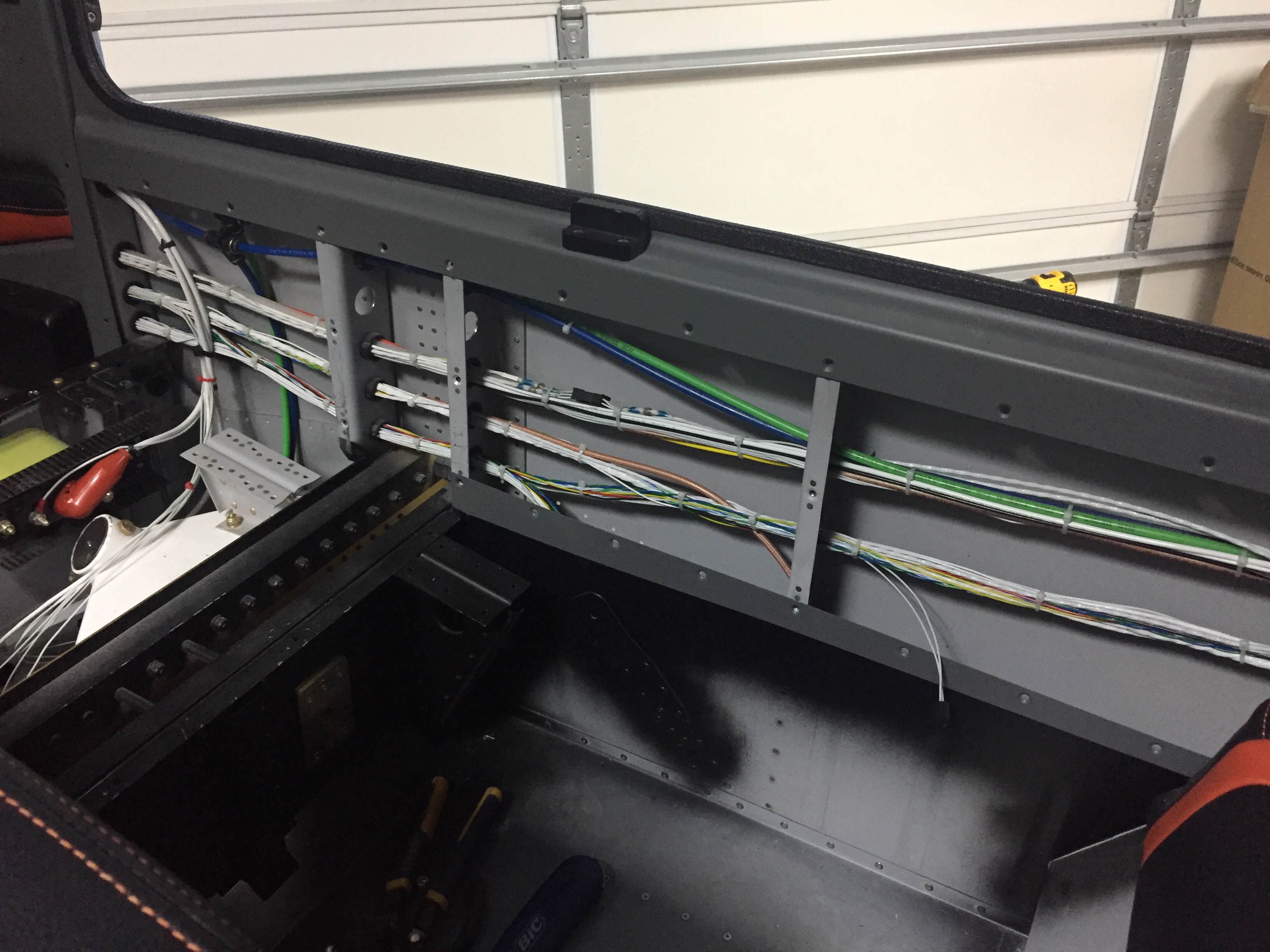
More zip tie work on the side walls as I cleaned up all of the wire bundles.  I was lazy and didn’t lace them.  If you don’t like that, you go build your own damn airplane!  Lots of zip ties.  Overall I’m happy with the wire runs, I was able to keep coax with mainly data / signal wires and have the high current ones seperated.  I have seen plenty of aircraft with everything bundled together without issues, so I think it’s more important to terminate and ground properly than anything.

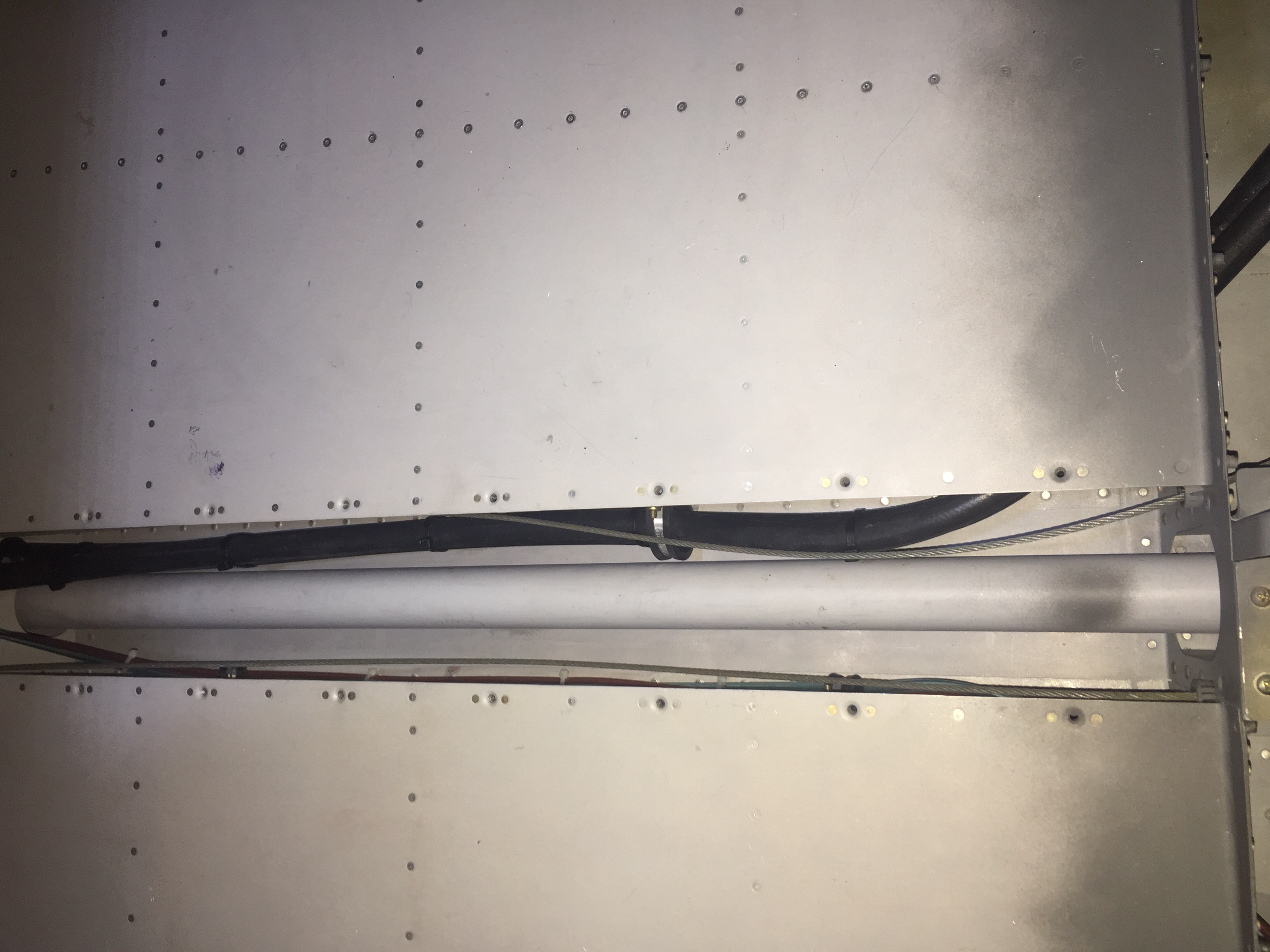
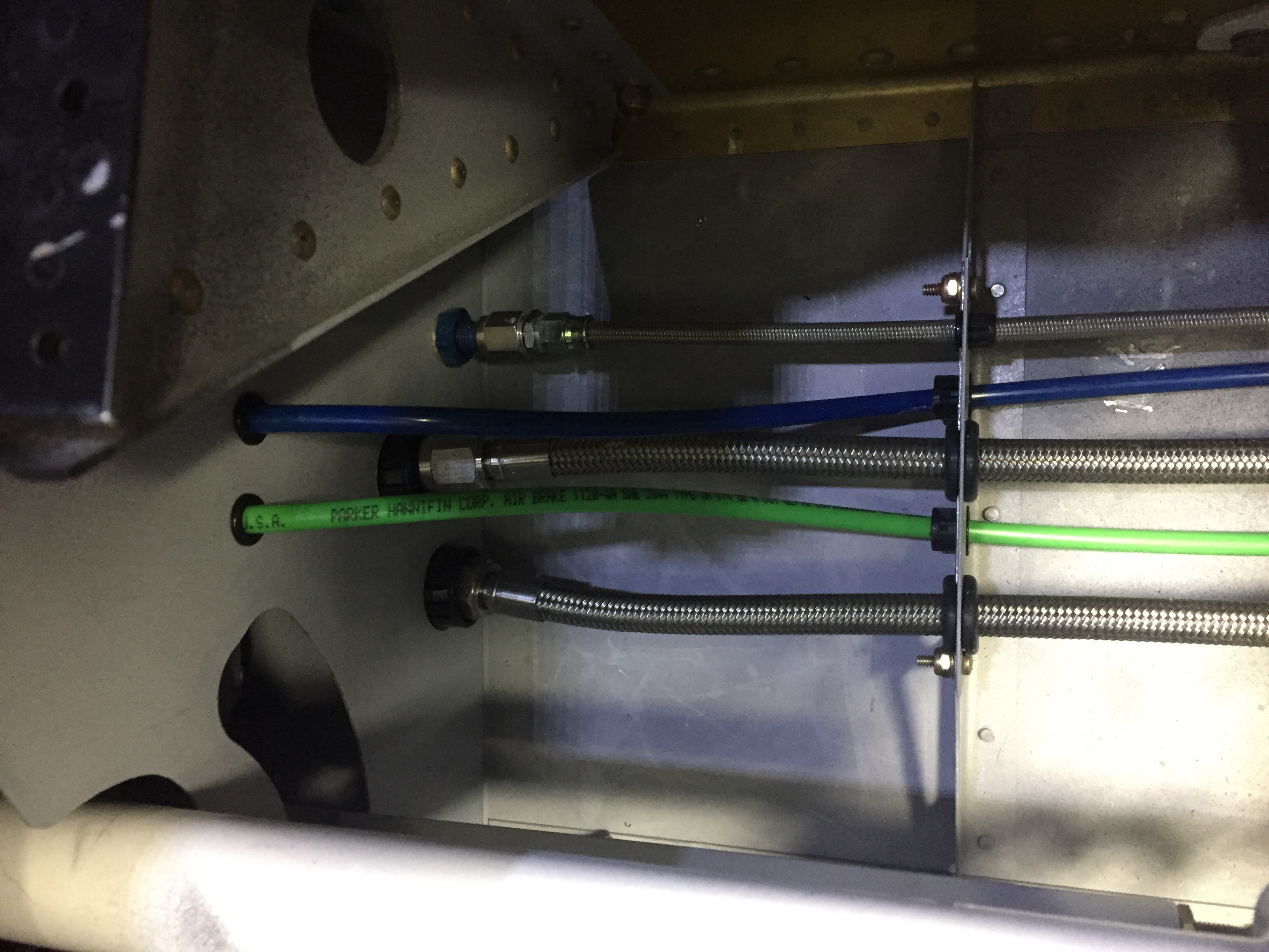
The pitot / AoA tubing needs to run across the fuselage from the left wing to the right sidewall, so I put two holes in the tunnel and used free holes from the fuel line anchors to run the blue and green tubing.  The wing is already plumbed, so these lines will connect with those from the wing with two connectors and be done.

Finally, I put the 30 amp Schottky diode on the firewall between the shunt and engine fuse block.  I had this in my electrical design but just in the wrong location.  It provides redundant power input to the engine fuse block only, keeping it from backfeeding the rest of the electrical system.  The power comes in from the emergency engine power switch which comes from the battery to the fuse block.  Big picture, it is a redundancy for the single point of failure of the master contactor or short in the system.  A complete electrical failure or engine stopping SOP will be to turn off the master switch (leaving PFD, MFD, and G5 operating on independent back up batteries) and switch on the emergency engine power switch.  If the battery has any juice at all, it will go only to the engine fuse block.

Smooth details

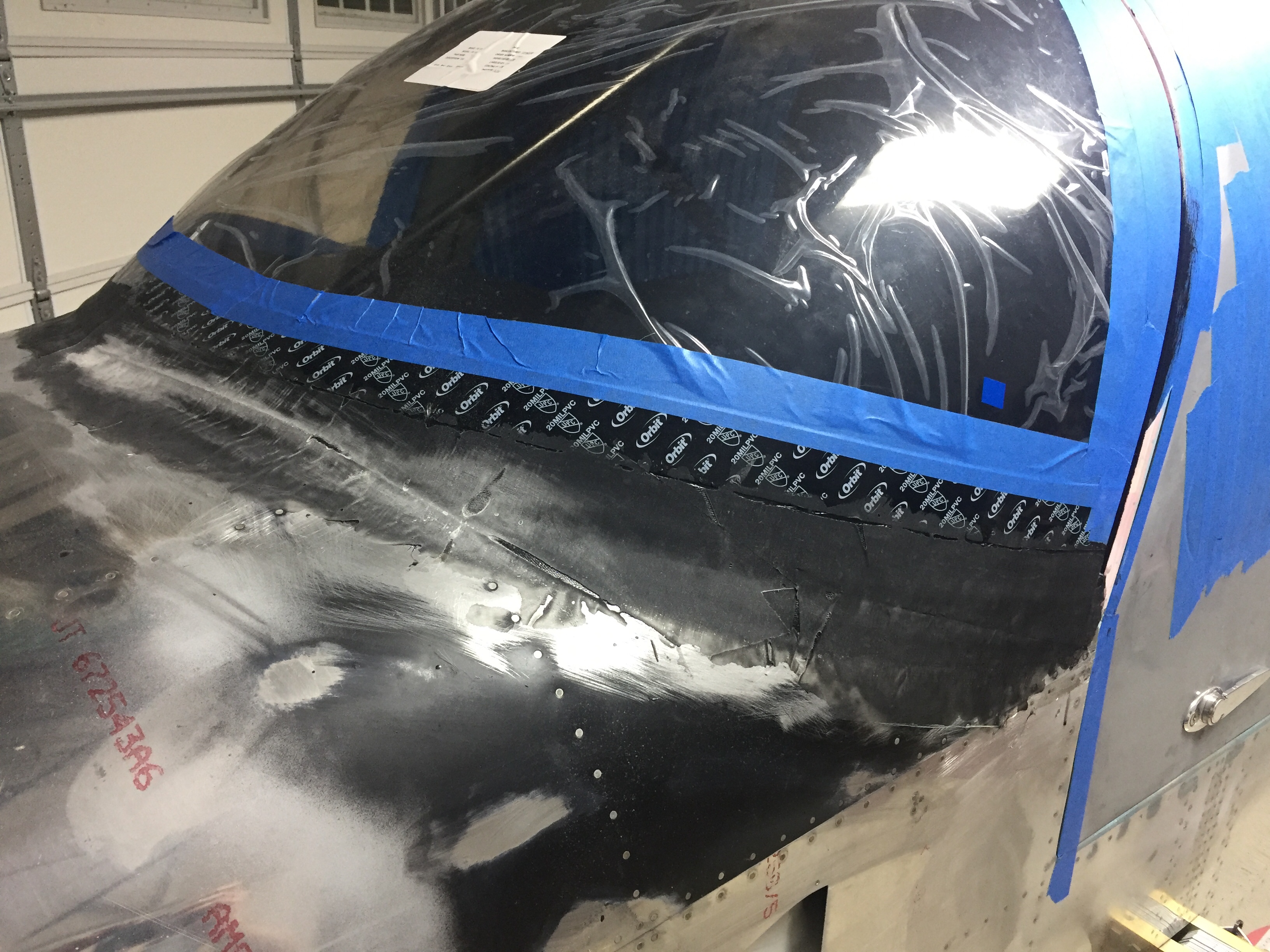
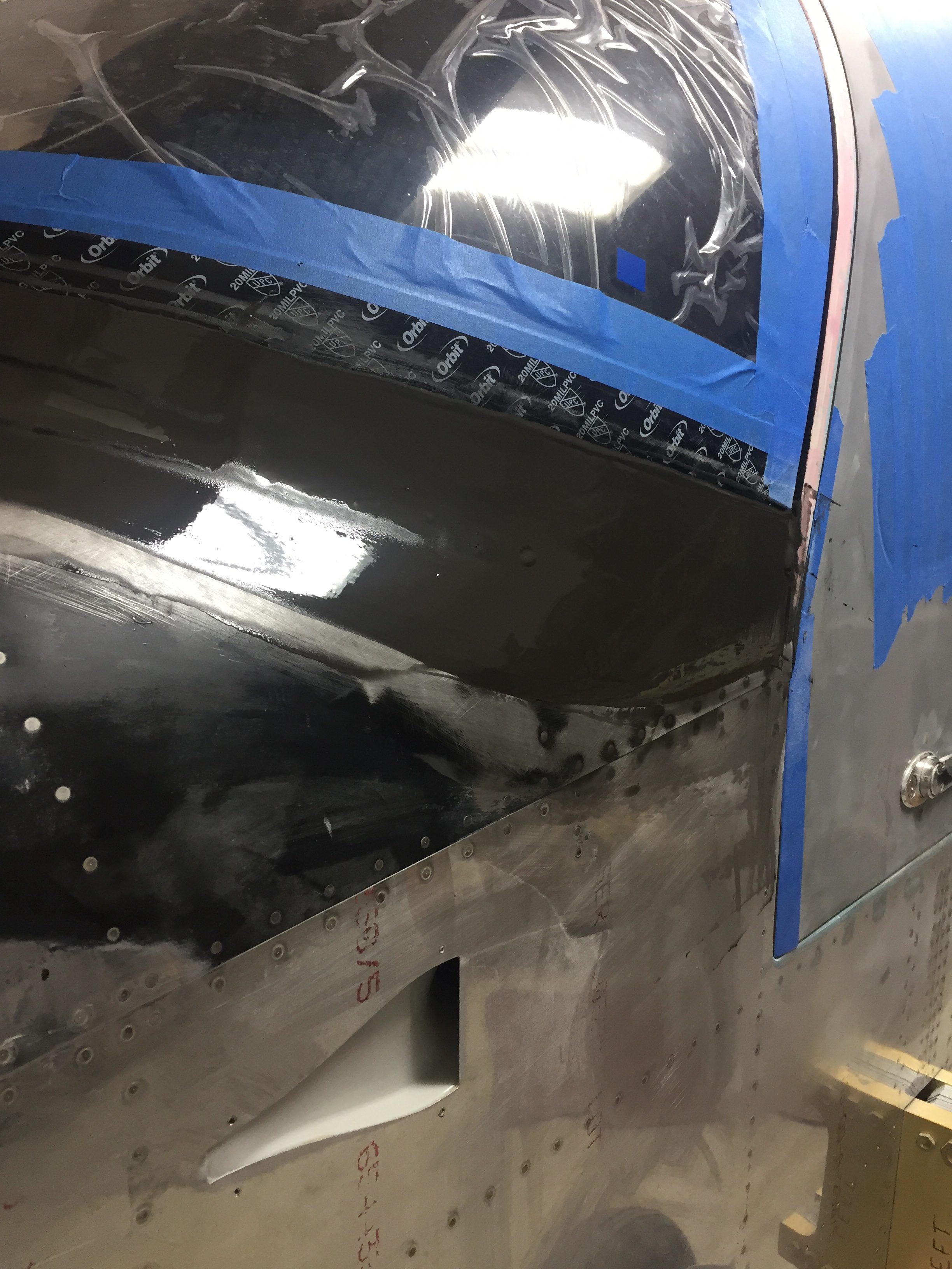
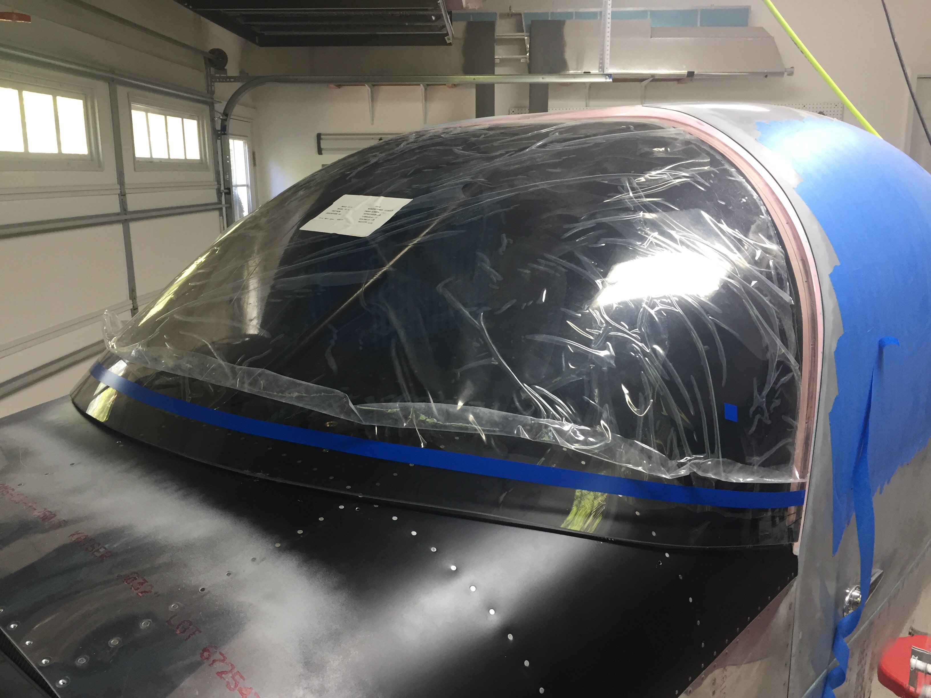
One of the last big fiberglass tasks is to layup the windshield fairing to the upper forward skin.  It’s a involved process with 10 layers of varying width glass strips followed up by a few coats of filler and epoxy to get it all nice and smooth.  I used cardboard to make a 7″ radius template and cut all of the fiberglass in preperation to layup the fairing.  I took other’s advice and died the epoxy black that will help create a nice finish from the inside with the Sika primer painted on the plexi.  This avoids unsightly views of the fiberglass from inside the cabin.  No pictures of the process as I had epoxy and fibers all over me, but it was a long afternoon with a lot of mixing.  I found that it was difficult to keep the layers precicely on top of each other and wound up with a few lumps and bumps along the way.  All were under the template radius, however, so could be fixed with filler.

The layup turned out pretty well and the next step is to apply filler.  I ordered a 2 mil vinyl plumping tape from Amazon Officially Approved Totally Legit Aircraft Supply Company and applied that over the electrical tape that marked the edge of the fairing.  This is probably the hardest aspect, as getting a nice smooth and even line is a bit challenging.  In the end, I did a lot of measuring and then eyeballing to get it good enough.  It probably isn’t perfect, but it looked good to my discerning eye.

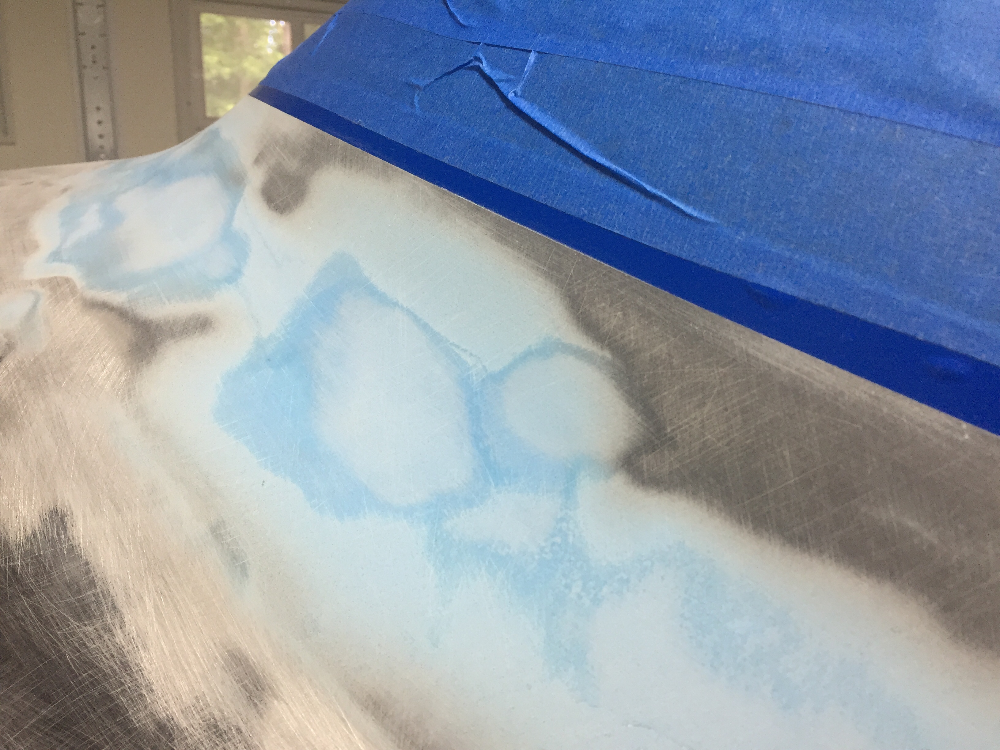
My first coat of filler was the West epoxy mixed with micro to give some good ridgity over the layups.  I died it black just be be sure a good coverage again and made it good enough under the template.  After a quick sanding once dry, I used SuperFil to complete the curve which is much easier to apply and sand.  All in all, it took about five applications to get everything just the way I wanted it.  I used my favorite soft curved sanding block to sand and just judged by feel any high or low spots.  I’m happy with the turn out and I’m sure Jonathan will touch it up when he takes the plane for paint next year.

On the inside, I have one little streak of white from the tape which is a bit aggrivating, but nothing I can do about it now.  It may be covered by the side panel and glareshield, so not too worried about it, but it just annoys me.  The rest of the windscreen interior turned out absolutely perfect.  Again, the Sportsman method of taping and using Sika was a huge aspect of getting a clean finish.  It’s really cool to sit in the cabin now and look out through the windscreen!  It’s also nice having the cabing almost entirely closed in to keep it clean.

I am getting the last bits of interior from Aerosport and putting them in place as I go.  The panel inserts came with the seats and turned out great.  They are easy to install and really add a bit of class and color to the interior.  The baggage bulkhead looks great as well with the EXPERIMENTAL embroidered on the leather.  I’ll be putting a mesh grille in the cutout for the aircon return vent.
I finally got started on the wheel pants as well now the gear is on and it’s exciting pulling more parts down from storage.  I really want these pants to be finished well and have a nice fit, so I’m taking my time prepping the seams and mounting points.  I’m going to use SkyBoltz instead of traditional nutplates to allow quick removal and installation of the pants.  I don’t plan on having access doors for the valve stems because I just don’t want to do the fabrication neccessary.  This way it forces me to have a good look at the tire and brake while checking pressures monthly.  FYI the SkyBoltz are far cheaper direct than from ACS.

One issue I had to pause on and get some help was the wheel pant spacer that bolts onto the wheel nut for the main gear.  On initial fit, it’s proving to be way too long and I was hesitant to cut it allowing the rear portion of the pant to fit.  Beringer says trim away, however, so I think it’ll actually save me a few steps later in the process since I’ll be able to trim at a precise angle to match the pant and avoid using flox to build up a flange on the inside of the pant.
Meanwhile, I fabricated the last of the stainless steel brake lines and installed them to the calipers.  I am now considering swapping the calipers from side to side which will put the bleeder nipple on the bottom.  I’ve always had the nipple on the top of the calipers, but using a pressure bottle to bleed the brakes from the calipers up will allow the air to be pushed up naturally instead of forcing it down and the nipples should be the lowest point in the system for this.  If the lines can still be used, I’ll swap them.

Next up is some exciting stuff as we jet off for vacation and engine build school in Kamloops, BC.  Stay tuned for details!

She’s got legs!

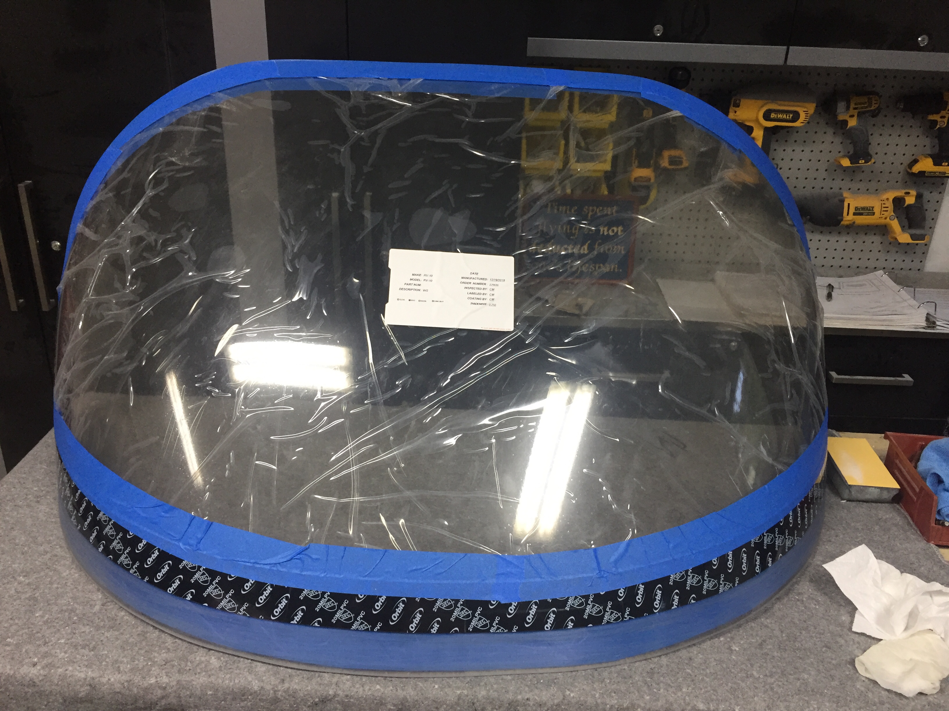
I continue to empty my parts inventory which is nice to give the space back to what it should be such as guest bedroom and bonus room upstairs.  A big chunk of floor space has been taken up by the windscreen.  Now, the story is I received my order from Cee Baileys many months ago but the box was damaged and the thoughtful FedEx driver decided to take the bundled plexi out of the damaged box and simply lay on the diamond plate steel floor before continuing the route.  Needless to say, my brand new windscreen was no longer brand new.  It’s not to say that it’s ruined, it just didn’t meet my standards.  I was lucky to only have a few tiny nicks that won’t even show up on a camera picture, but are visible if you look hard enough.  A claim and call back to Cee Baileys had a replacement in a better box on the way to me.  I plan to sell the original one at a good discount and it may work for someone building on a budget or as a repair, who knows.  Either way, my fuselage was ready for a windscreen.

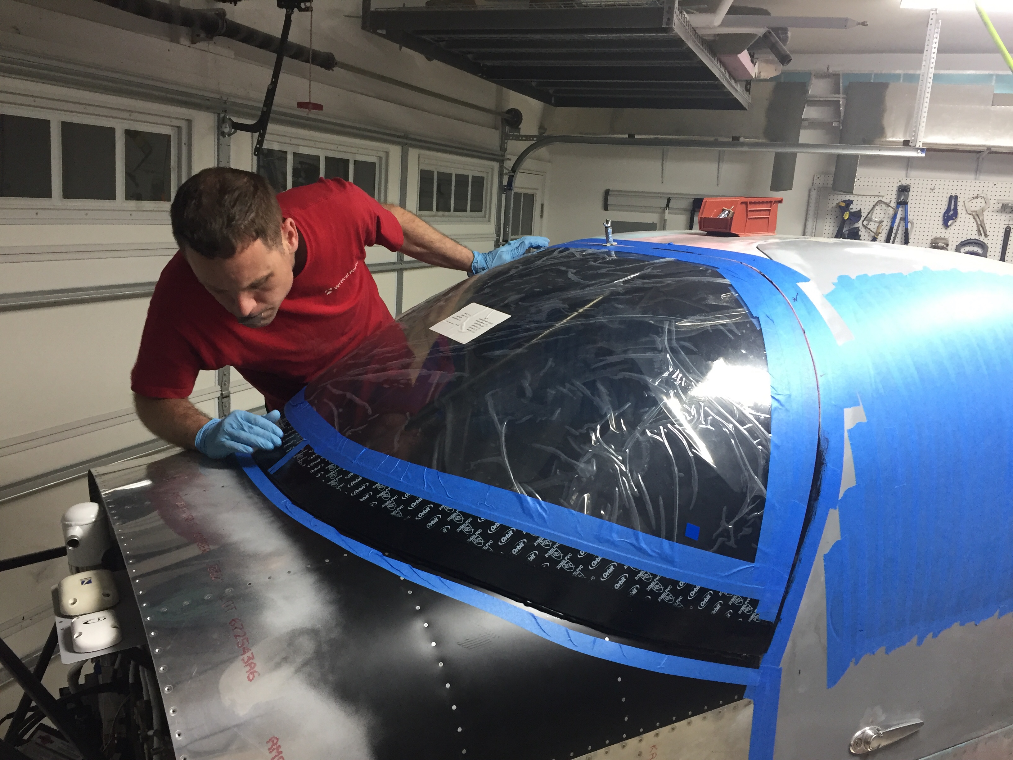
I prepped it just as I did on the windows and since I had already rough trimmed it, I was able to get the final fitment completed in just one evening.  I’ll be using a mix of methods to install it, following the plans on the lower edge and using the Sikaflex method around the cabin top.  I again traced the edge of the cabin top onto the plexi so I could tape it using the sportsman method.  It was actually easier since I only had half the area needing taped.

I also ground down the two side corners of the plexi to allow a nice flat surface once the fiberglass layup is applied.  I’ve seen and heard others having a buldge on either side of the fuselage and most women find buldges unsightly and moderately annoying.  This is all about impressing the ladies, so no buldges on Tess!  I decided to apply the Sika primer on the outside of the bottom area to help hide the fiberglass overlay.  I also have black die for the epoxy.  Once the skin was roughed up, I laid a good bead of Sikaflex down and Laura helped me set the screen in place.

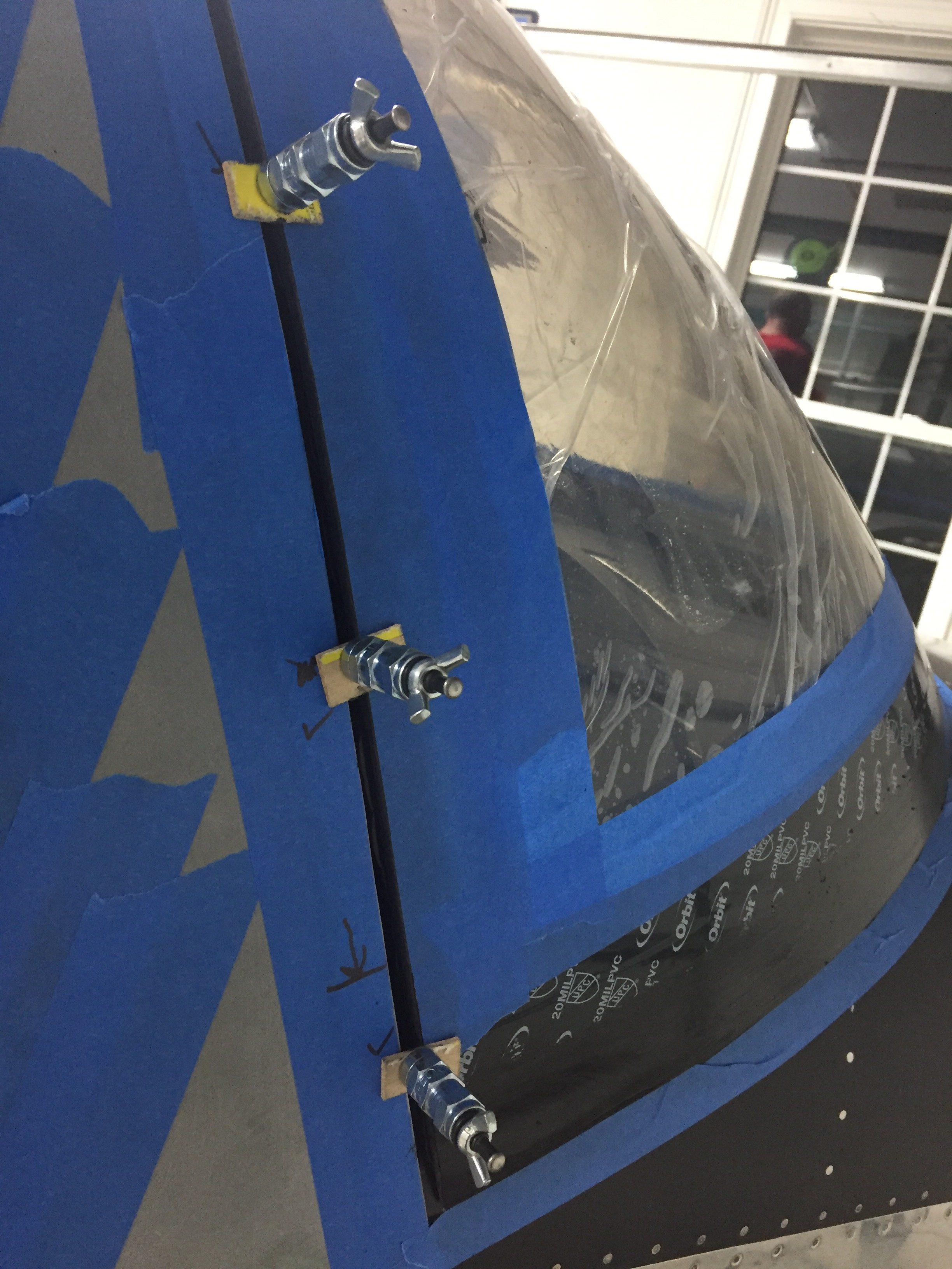
I worked quickly again to put the wing nut clecos in and level out the screen to the cabin top.  It went well and soon enough it was time to clean up the inside.  Again, time spent prepping the tape proved to be priceless, as the inside of the screen came out perfect and professional looking.  I didn’t have any sealant on the plexi at all nor did any get on the cabin interior paint.  All in all, I’m really pleased with it.  Once the Sika cures, I’ll start on the fiberglass fairing at the bottom.  Again, the Sika will fill in the gap around the rest of the windscreen after paint is completed.
The next project and main goal before the engine arrives this summer is to get her up on the landing gear.  I bought a fancy Harbor Freight engine hoist to assist in the task and after some usualy frustration at assembling a HF tool, it was ready to roll.  I had a friend who’s building a Glasair come over and help with the lifting of the fuselage.  It was nice to have a extra set of hands besides Laura’s and my own.  He hooked up the chains on the engine mount as I padded a workbench and got the components ready.  The lift was really a non-event but nerve wracking none the less to see the fuselage hanging in mid air!

I had already built up the brake calipers and wheel pant mounts to be ready for the install and to be able to do that on the bench vs on the floor.  With the Beringer setup, a lot of the setup is different but ends with the same result.  The spacers are all machined and an extra hole has to be drilled in the wheel pant mount.  A larger hollow axle slides over the stock axle area and a pin is used instead of a through bolt.  The Beringer items are such quality and fit great.  I did have to dremel a bit of the pant mount to clear the gear leg since it’s slide inboard a little bit.
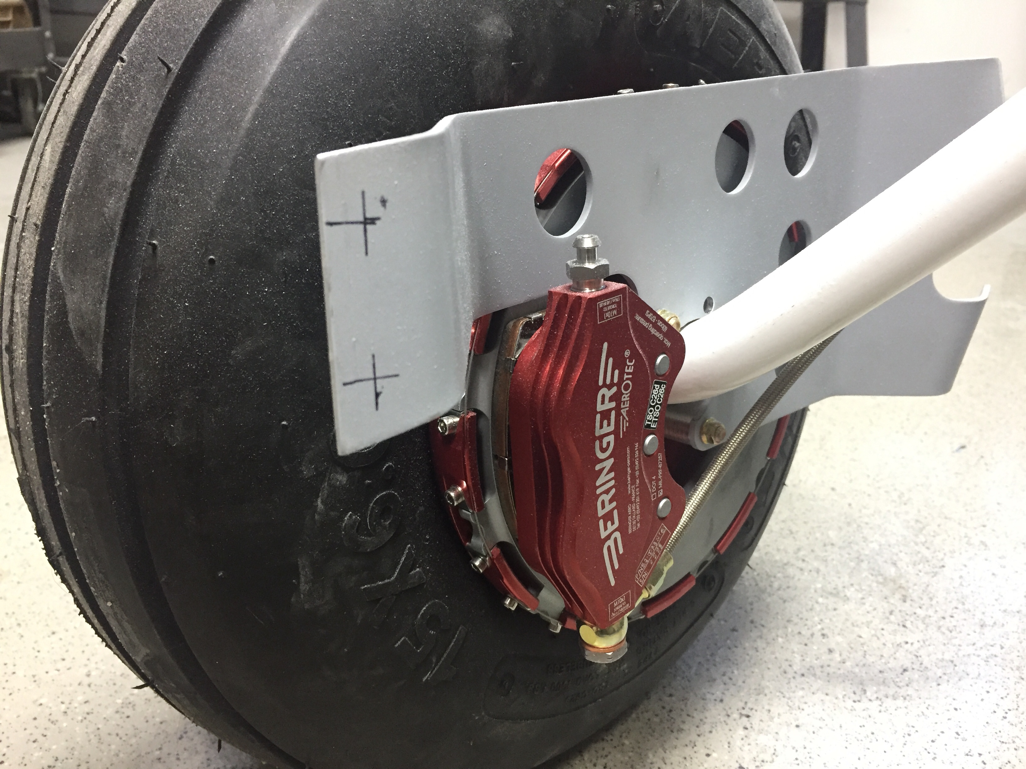
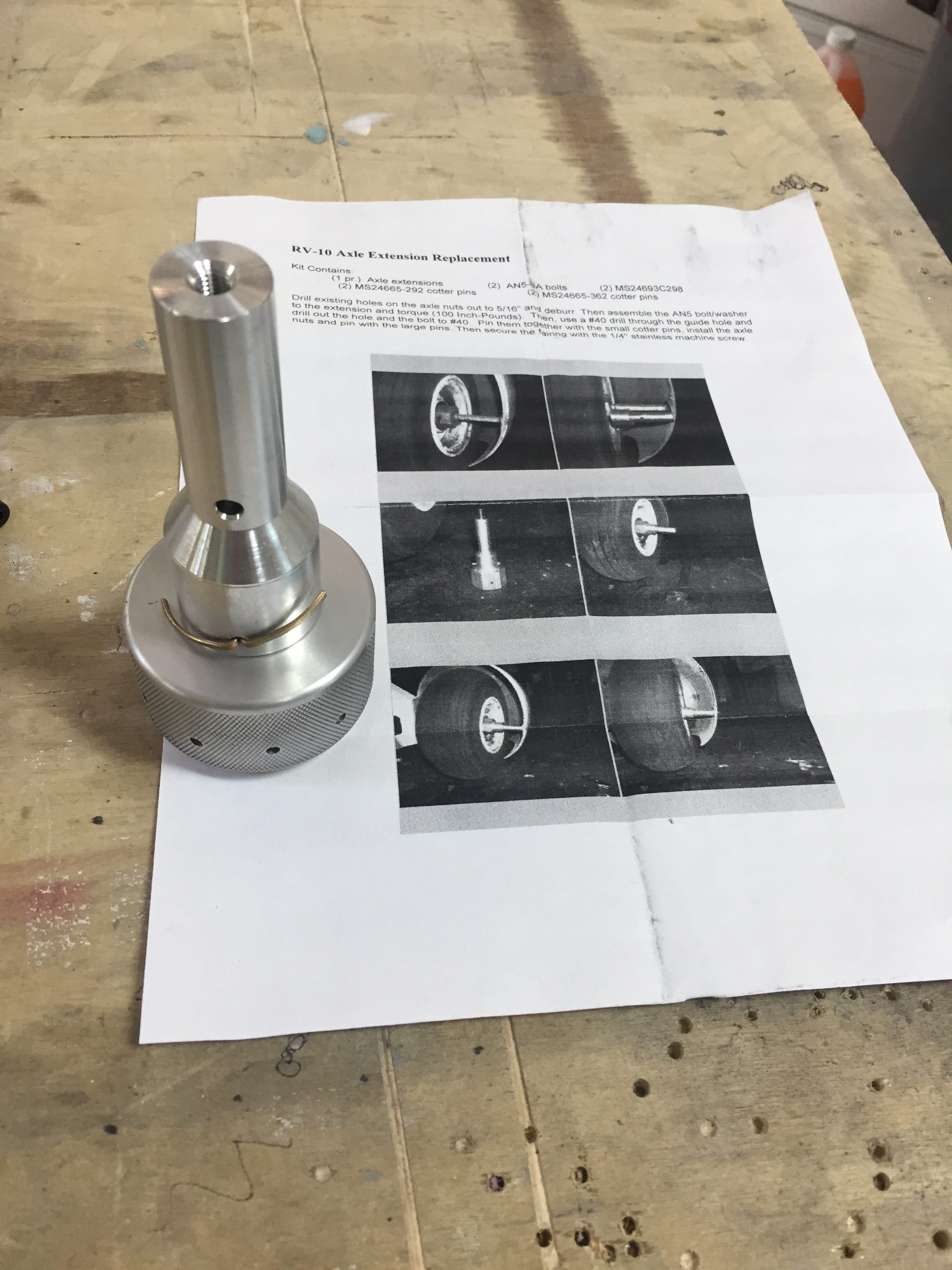
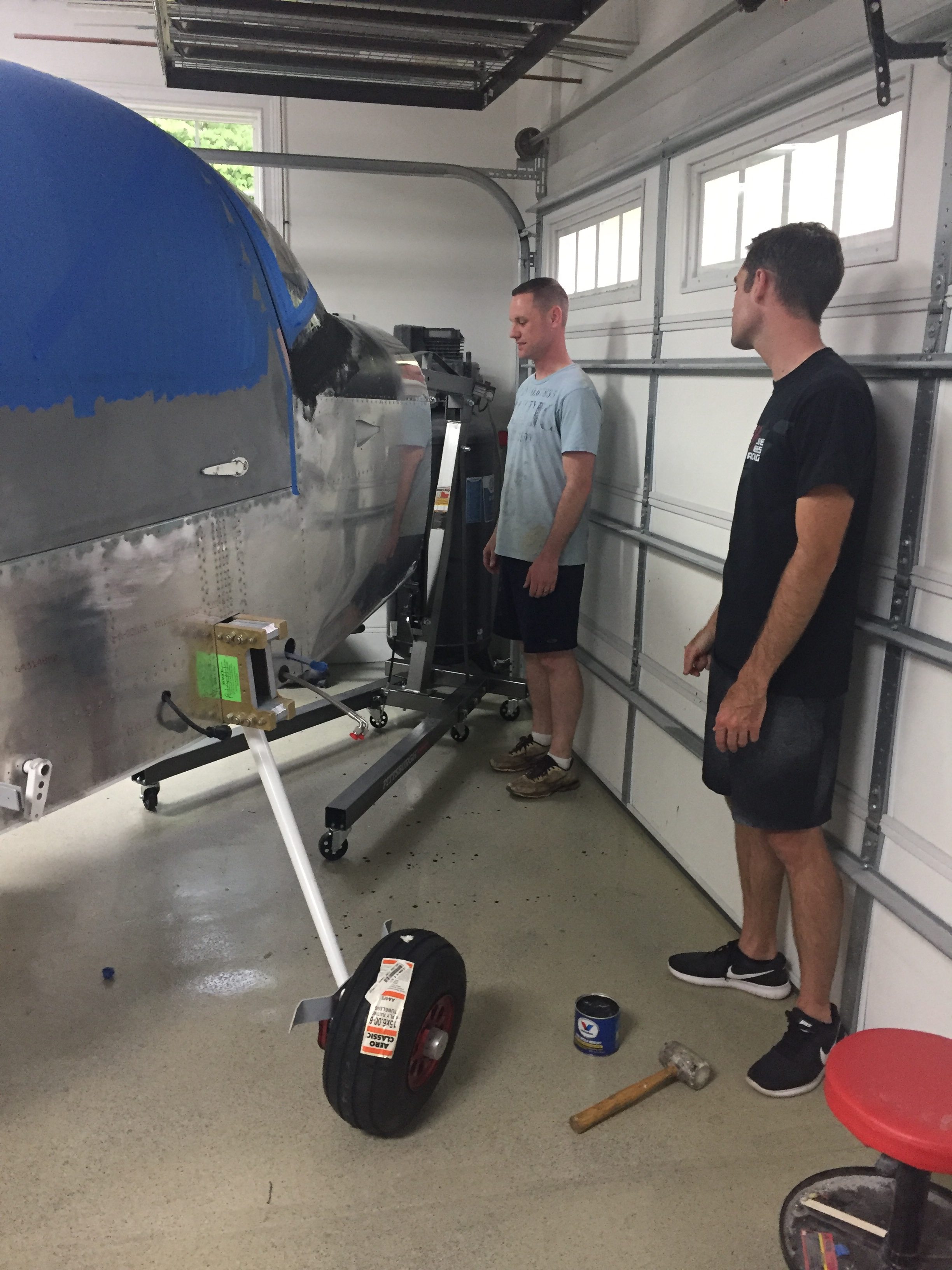
The left leg put up a bit of a fight, as I didn’t sand down the edge of the powdercoat so it didn’t want to slide all the way into the mount.  Once I figured that out, I made sure not to learn from it and pressed on drilling the hole for the bolt.  Yet again, very anti-climactic for such a momentous achievement!  We slid the main wheels on and lowered it down onto the gear for the first time.

The nose gear leg was bolted on pretty easily and we were ready to compress the pucks/strut to get the cap and bolt on next.  Remember when I said I was sure to not learn from the powdercoat edge?  Yeah, we spun our wheels and cranked on ratchet straps for an hour with no luck getting the strut cap to aling properly.  Clearing my head for an hour to go get more tools helped me finally learn and the lightbulb popped on to sand the strut a bit.  The cap fell into place easily after that and didn’t require nearly as much compression as we had initially put on the gear leg.

The next bit of ignorance on my part came in putting the bolt through the cap.  The plans called for it to be inserted from the starboard side.  I thought, it doesn’t matter.  Well, Tim, it does matter.  Follow the plans!  The hole is slightly twisted to clear the heat vents.  I wound up getting it in from the port side but made it difficult for myself.

With that complete, the nose wheel went on and she now has her legs under her!  The Beringer wheels look amazing, too bad they will be hidden under wheel pants.  I left the tail stand on until the engine is hung but still had to chalk the mains since it rolls so easily!  I took advantage of the new mobility to roll Tess outside for some sunshine and a good shop cleaning.

Fans of all shapes and sizes

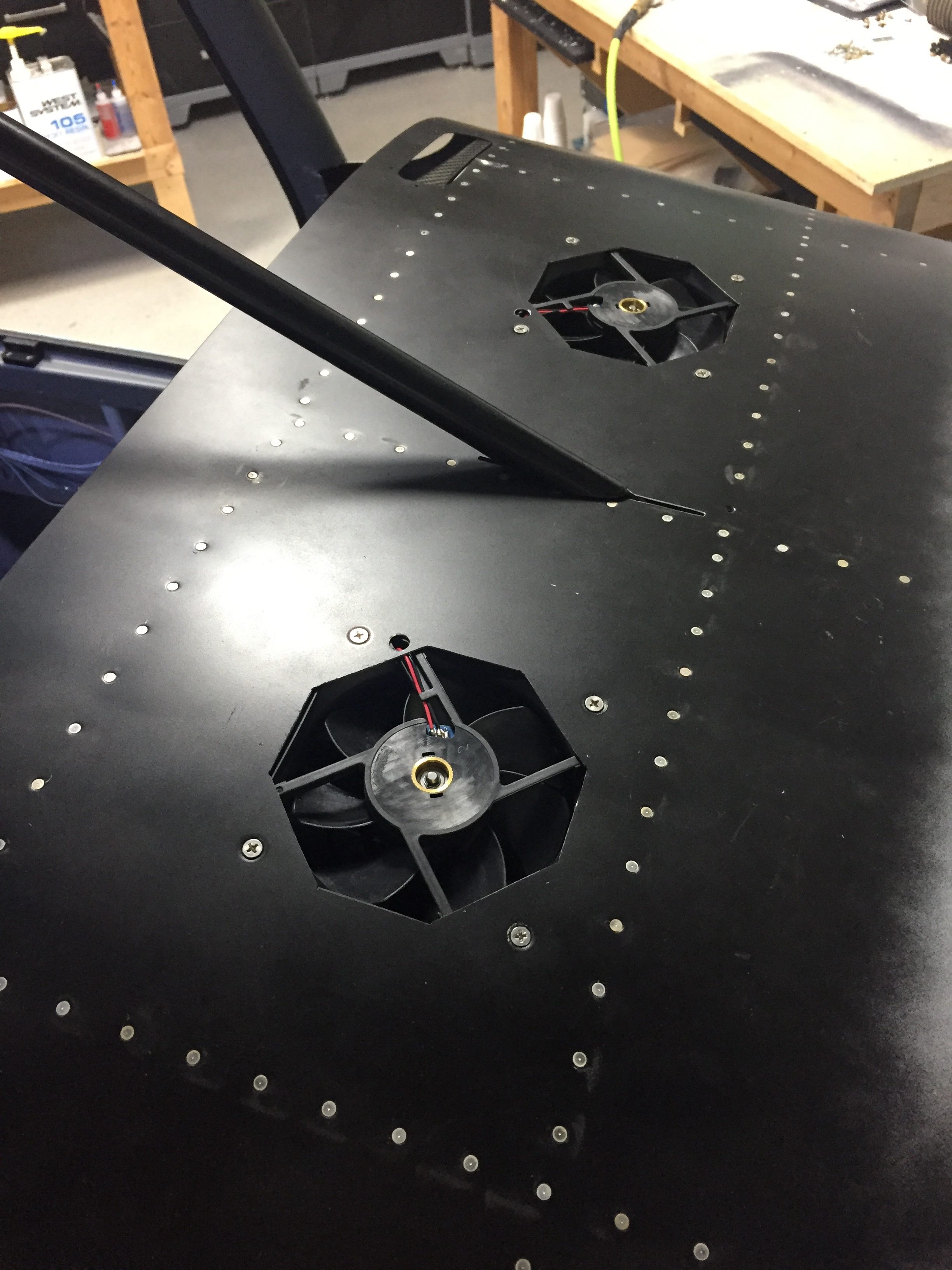
Two jobs still linger before I can rivet the front skin on; defrost fans and bolting in the support bar.  The defrost fans were pretty simple, as I already had the wiring in place and holes cut.  I just needed to drill screw holes and mount them up.  Although a bit tough to get to, they were eventually bolted in and tested out.  I probably could have gone smaller or lower CFM, but go big or go home.  I shouldn’t have any fogging issues!

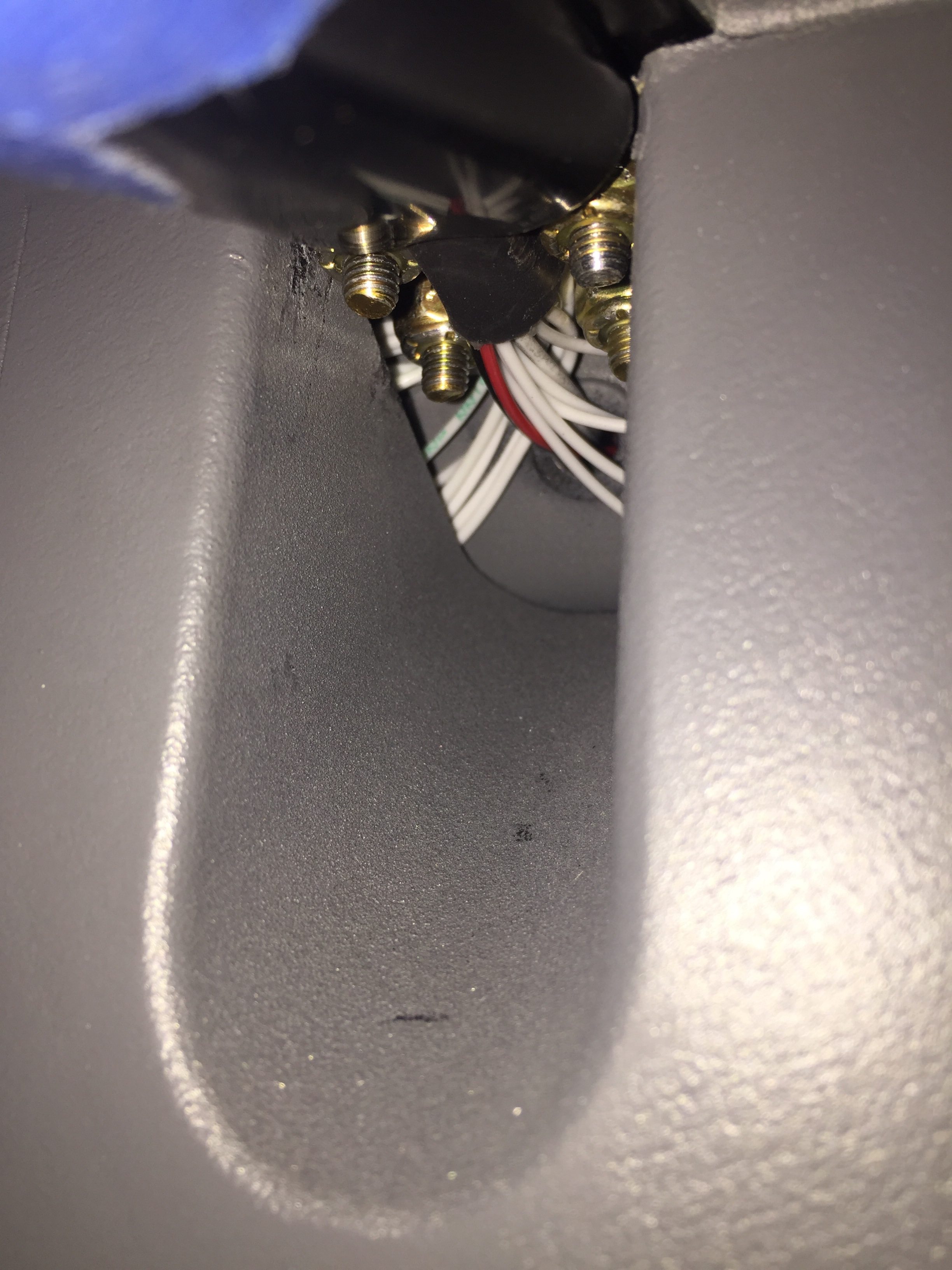
The support bar was one of those jobs that I have put off due to dread.  Since I molded the overhead switch panel into the cabin top and overhead console, the access to the four screws going through the cabin top is extremely limited.  Added to that is the hunky chunk grip of wires I have running up the bar to the overhead.  My dad was in town for a few weeks so I decided to get his help and tackle the task.  We were able to get the first two screws in pretty easily by sliding the wire harness to the empty side.  I put the nuts on finger tight and then had to mulitlate two sockets to fit up agains the switch panel since it was so close fitting.

The other two screws were a bit more challenging, as I had to slide the wire between the screws now and wrangle the washer and nut around them but beside the switch panel.  As with a few jobs, a lot of cuss words were uttered, a tool might have gotten tossed gently onto the floor, and after a lot of sweating and questioning why I didn’t just buy a Cirrus later, it was completed.  I’m glad I won’t be taking this apart regularly.

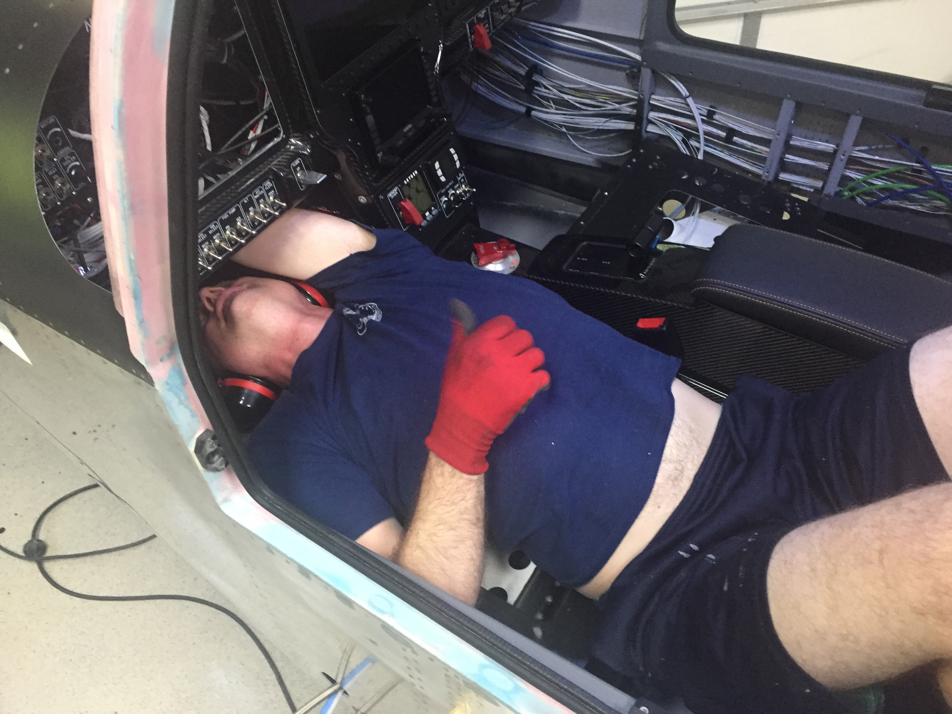
All that cussing and sweating just primed me up for the next job, riveting the upper forward fuselage skin onto the structure.  Since dad was here to shoot from the outside, I grabbed my PPE and dove under the panel in one of the most uncomfortable positions I’ve ever been in since I was born.  The rivets went in smoothly and we were able to knock it out together in a few hours, but man it is literally a back breaker.  I had positioned all of the avionics so I could reach the rivets, but it was still tight.

For anyone reading this that hasn’t reached this point or is considering building a 10, PLEASE TAKE THIS AS A PIECE OF WISDOM HANDED DOWN!!!  Do NOT rivet the forward fuse / skin on until AFTER you have all of your avionics and wiring in!

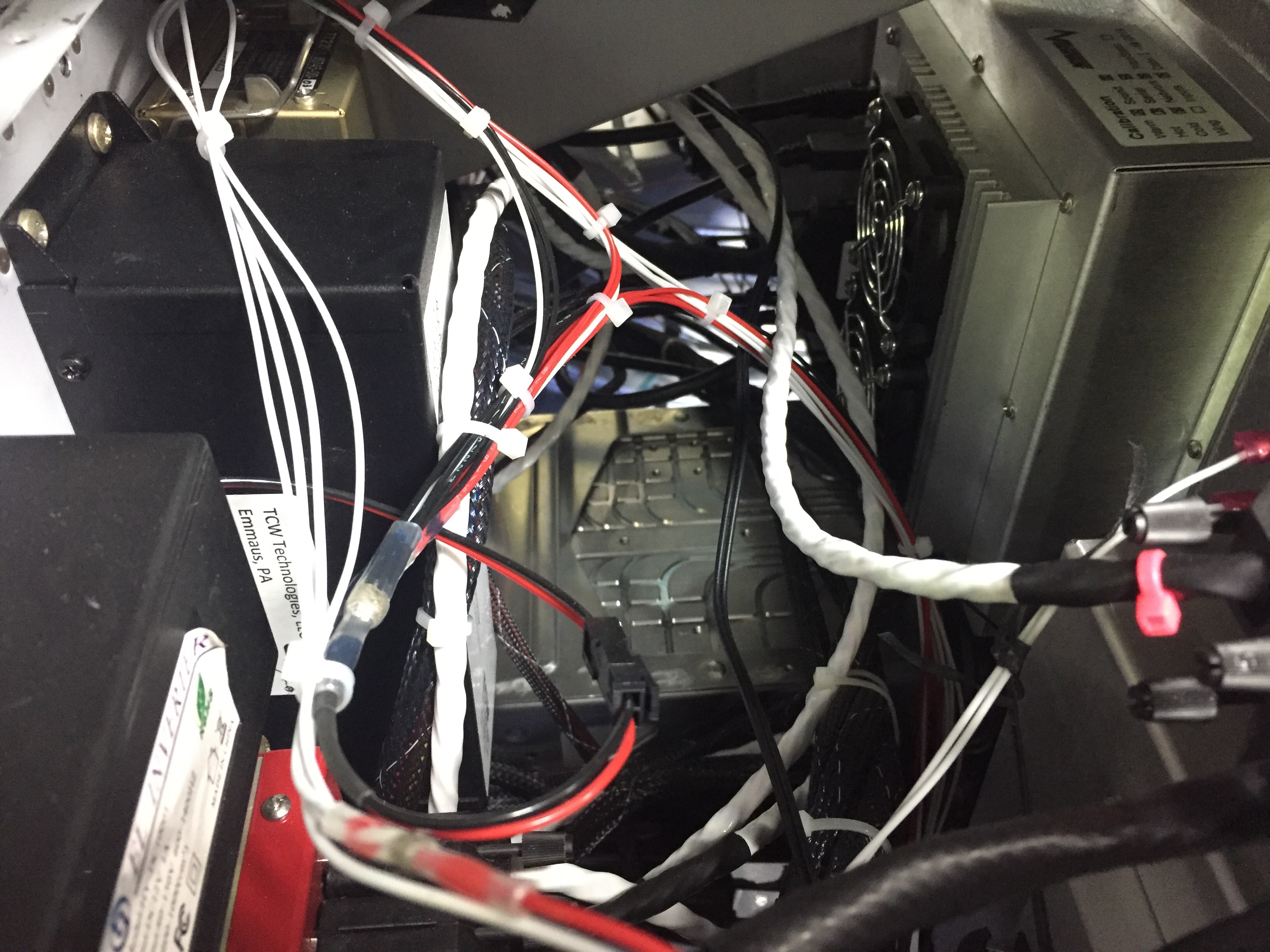
I can’t imagine spending days laying like that running wires, terminating connectors, and trying to bolt crap onto the subpanel.  I kept the structure and skin off as long as possible and was able to simple walk around the avionics bay to complete everything.  It would have taken me twice as long to complete the wiring if I had followed Van’s plans.  I took the opportunity while under the panel to add just a few more zip ties to the wiring runs that I had already permanently secured.  It’s not immaculate, but I’m very happy with my housekeeping and wiring runs.

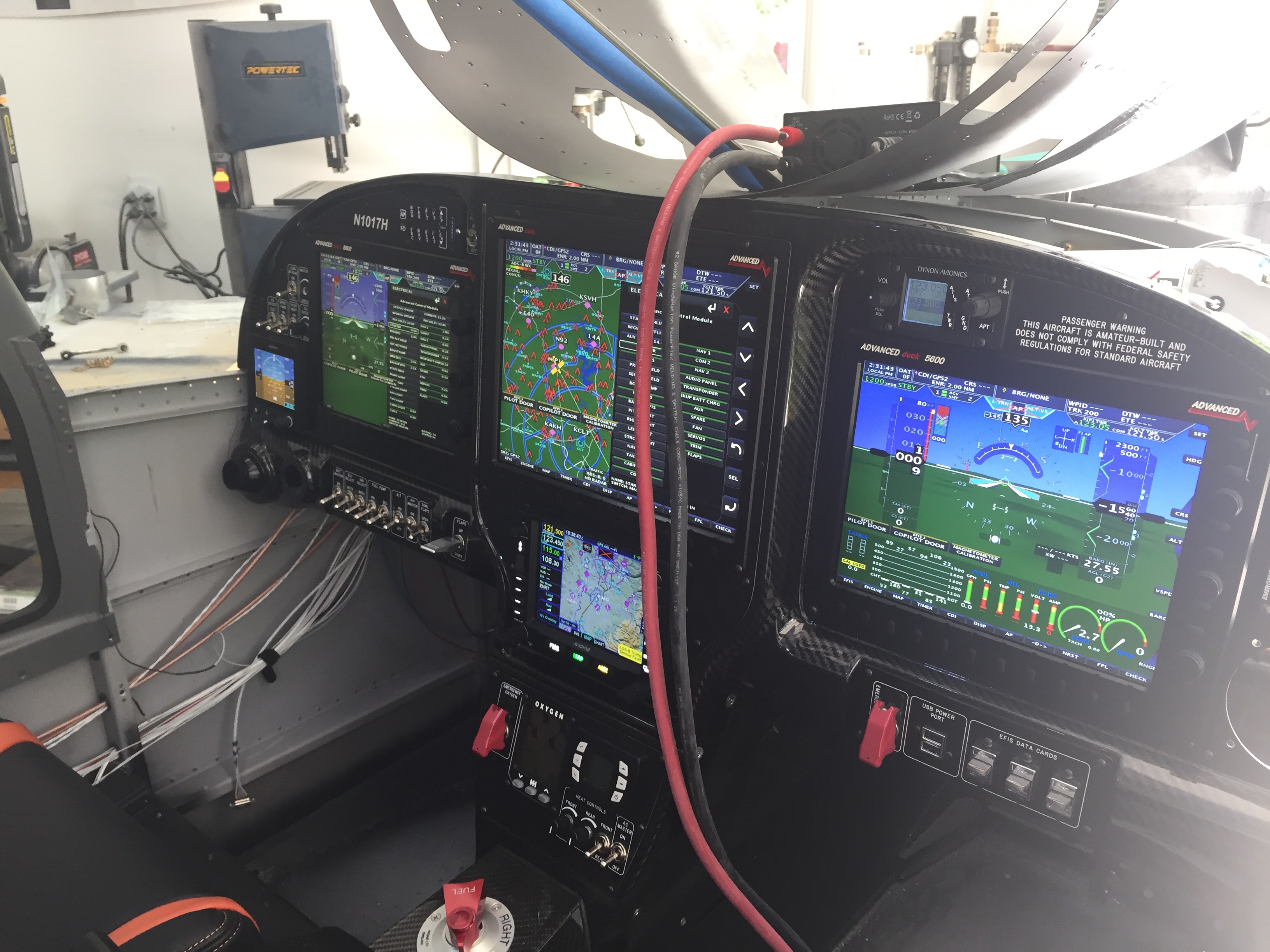
It’s cool to see the batwings gone now up front and the plane is really looking like a plane!  I put the PFD/MFD screens in and tidied up a few things which at this point completes the avionics.  All components have been installed and successfully tested sans the ECUs which will come with the engine in July.  I’m trying to minimize the time spent playing with avionics, because to be honest, I won’t get any building done if I’m swiping and experimenting with instrument approaches to JFK!

Finally, all of the aircon relays came in and I was able to properly test the system without the compressor, of course.  The condenser fan that I upgraded as part of the redesign really pumps some air and I’m really optimistic that it will produce good cooling for the condenser.  I installed an Aerosport headset hanger on the overhead console panel and reinstalled the panel to enclose the overhead.  With it all sealed up now, the cabin fan is very effective, even on low, at pushing air over the evaporator and throughout the cabin.  On high, it’s more air than I get through the vents in my car, so I’m again optimistic that the aircon is going to be very effective even on hot muggy days here in the south.

Next up will be the windscreen followed by getting the landing gear on.

Cool Colors

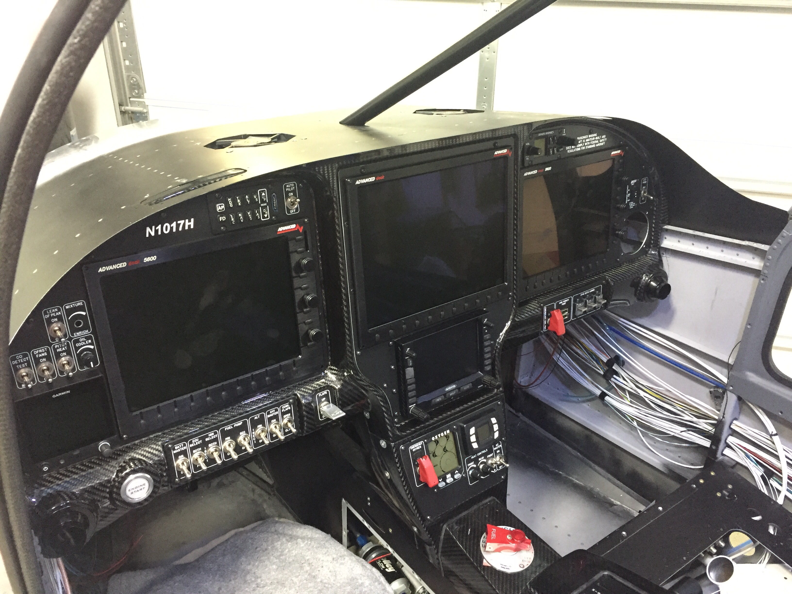
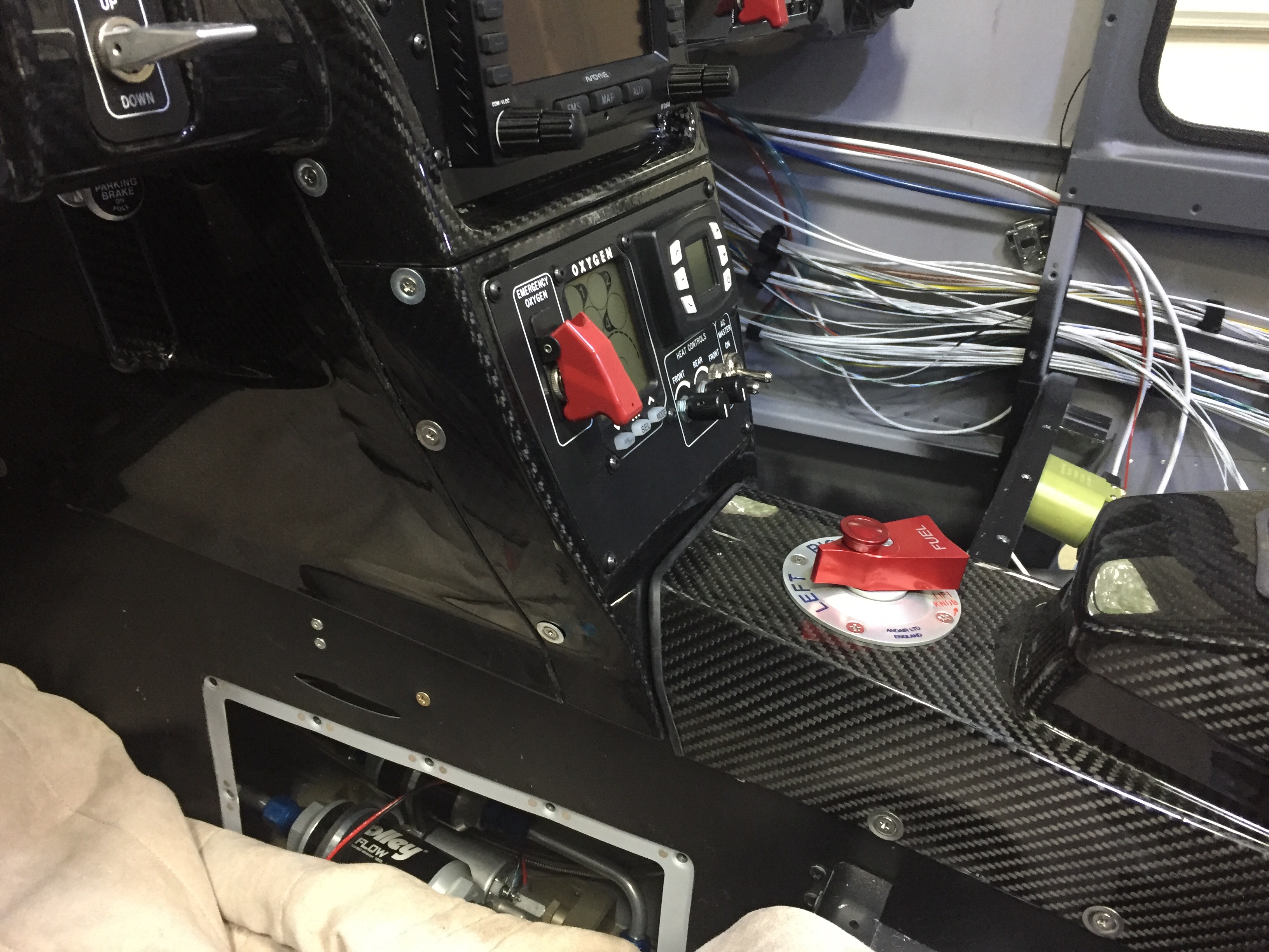
I have fully recovered from the traumatic smoke incident and have made progress on completing initial testing on all of the electrical components in the plane.  I buttoned up the tunnel and got the tunnel cover and lower panel console installed.  I am lucky but allowed JUST enough length in wiring for the components on the lower panel including O2, aircon, and cabin heat controls.

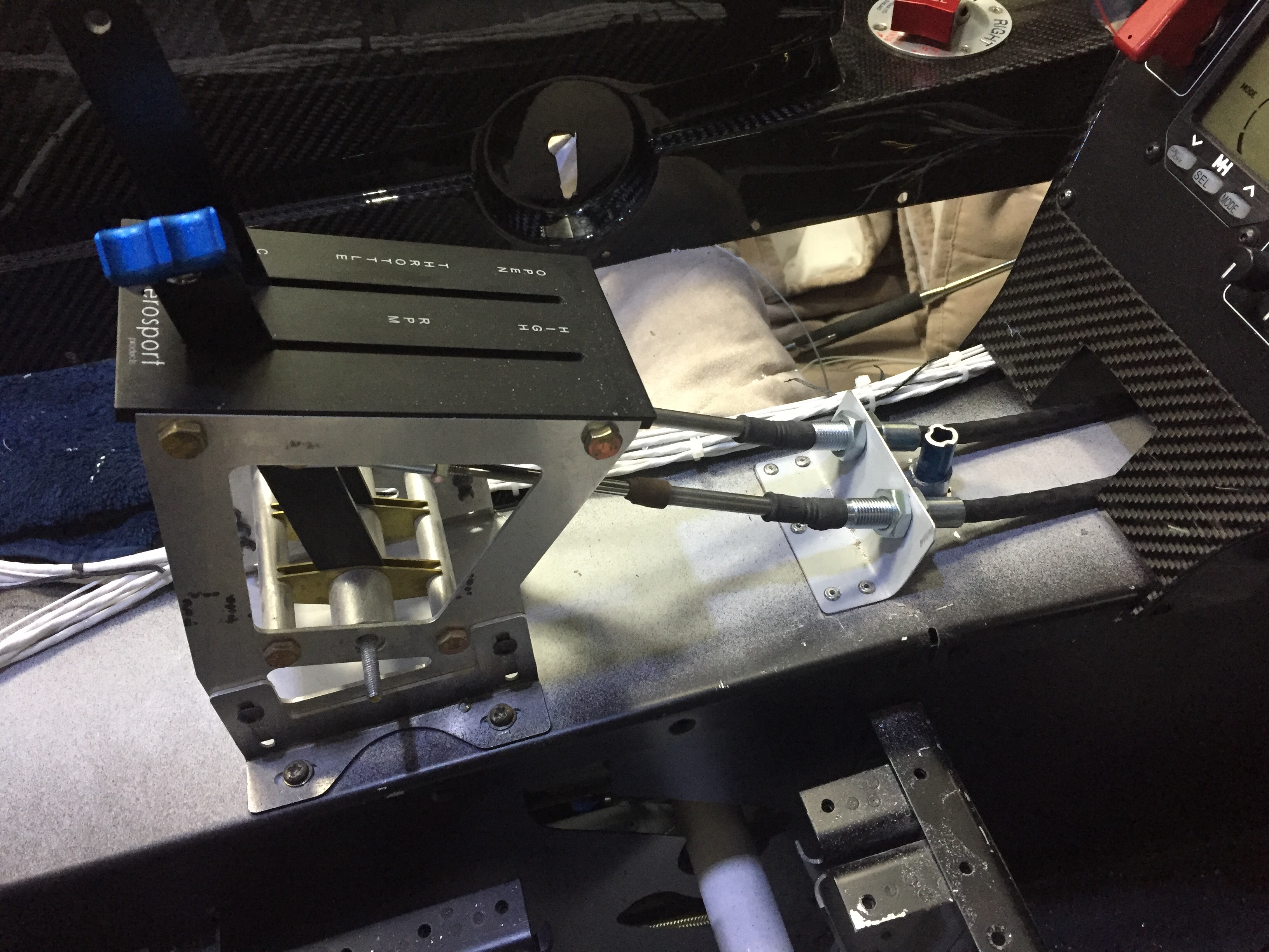
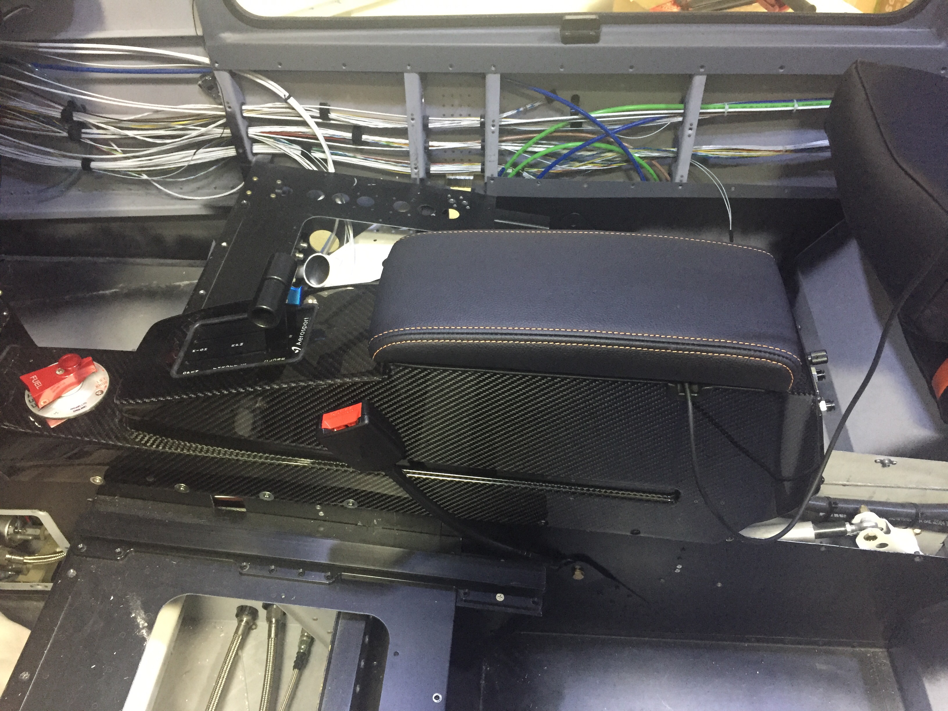
The center console was next to install and went in pretty easily all things considered.  I finished odd jobs with the audio jacks, USB power port, and the wiring runs on top of the tunnel cover to get it all cleaned up.  I also mounted the throttle quadrant for good and fabricated a bracket to route the throttle and prop cable to the quadrant.  All of the O2 lines were hooked up and the fuel selector was verified in the correct position corresponding to the selector.

I haven’t installed the front seat O2 ports, so can’t test the oxygen system completely, but the power and back light input functions properly as do the rear controllers, so I’m optimistic it will all check good.  The only item that gave me a bit of trouble was the aircon. I have the aircon fuse block (bus) powered via a 40 amp relay and master switch to allow for rapid load shedding should I need it.  The switch, relay, and control head all works but I wasn’t getting either fan to come on.  I double checked all connections and wiring runs were correct to include the drier, high pressure switch, and thermostats.  I should have at least gotten the cabin fan coming on but the 24v relay wasn’t clicking on for the selected speed.  That’s right, the 24 volt relay.  Not the 12 volt relay, the 24 volt relay that I’m expecting my 12 volt system to activate.  Dammit.  It took me sitting in the back reading voltages for about 15 minutes with Laura at the control head to figure out the error.  I never put two and two (or 12 and 12) together, so grabbed two spare 12 volt relays and swapped them out.  Sure enough, proper function of the cabin fan and condenser fan!  I ordered new relays and swapped them all a few days later.

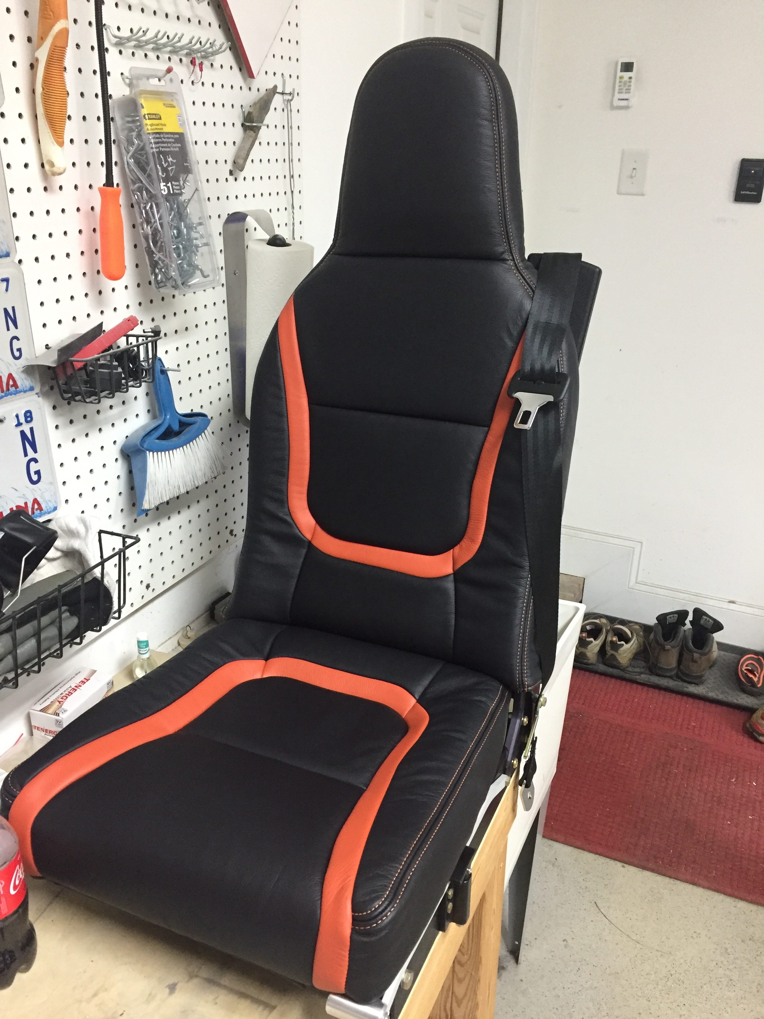
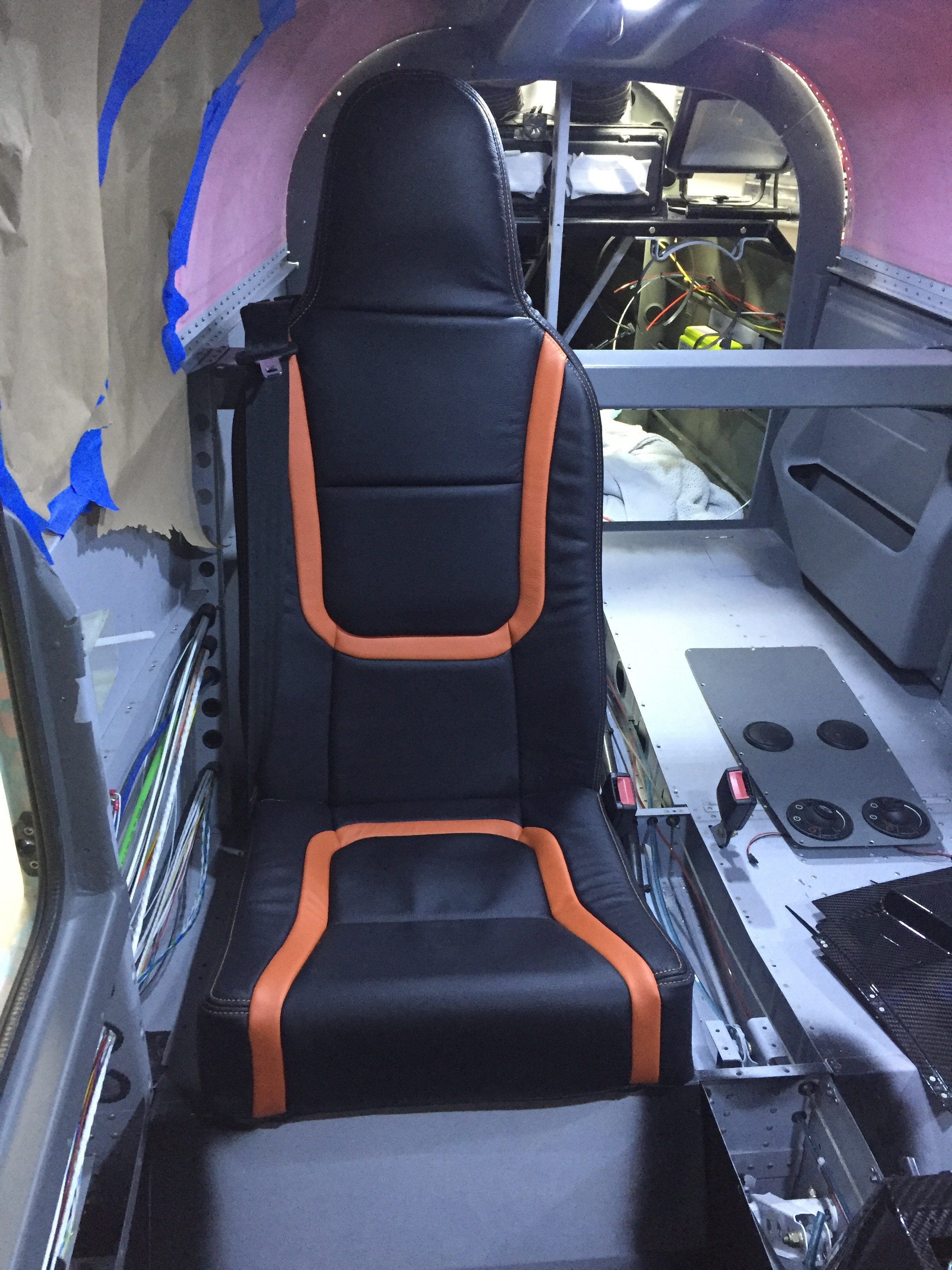
Meanwhile, I received two big boxes full of leather upholstered seats and goodies from Aerosport!  Andrew has been pretty patient with me and man did it pay off!  The seats came out perfect and just what I had imagined.  The orange stitching looks great on the black and matches the leather I sourced perfectly.  They made up the side panel inserts as well as the stick covers and armrest pad, all looking very high end.  I couldn’t help but build up the front seats to see what they look and feel like.

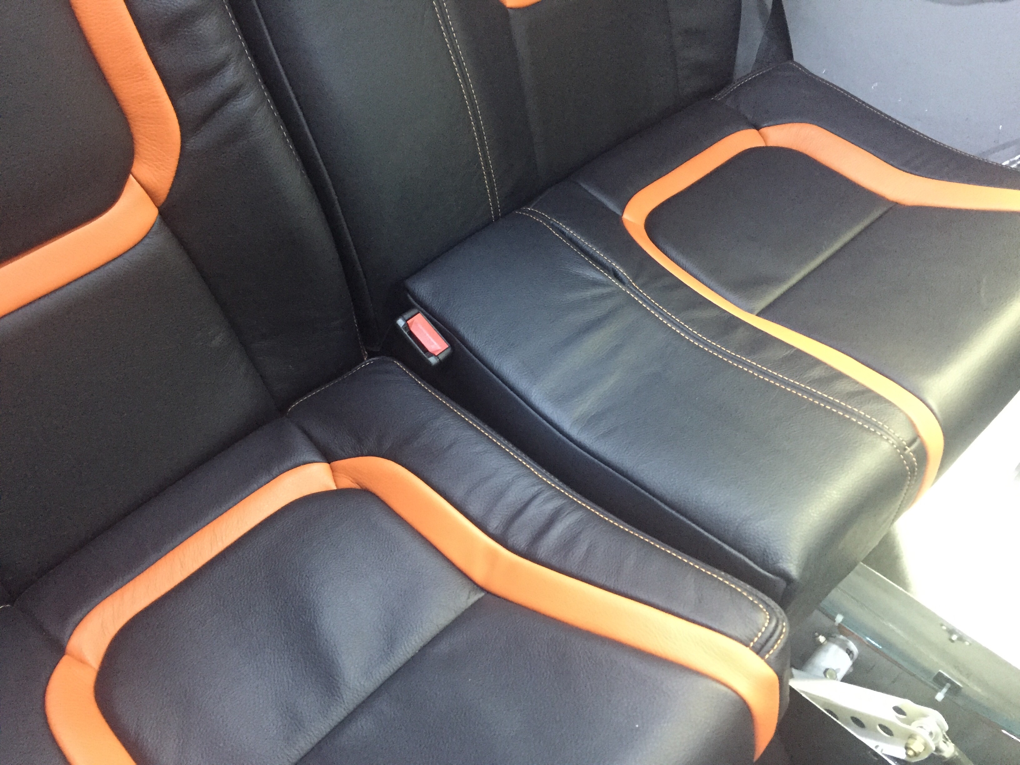
The back seats came out just as awesome as the fronts and feel super comfortable for passengers.  I cannot say enough great things about Aerosport’s stuff, except for their prices!  You do get what you pay for, however, and this is an area that I didn’t want to go cheap on.  Andrew changed up the plan a bit on my front seat belt brackets by designing and 3D printing a cover for the bracket.  This worked out, as I had to open the bracket and widen the belt channel about 1/16″ to get the belt to retract easily.  If Aerosport had done the leather like I had asked, I would have had to pull the entire seat back cover off and I’m sure it would not go back on as well as they have done it.

The left rear seat bottom cushion was the only hiccup, as the seat belt receptacle doesn’t quite fit in the slot they sewed.  Andrew is already on it and I sent the cushion back for modification along with the rear bulkhead substrate after cutting the aircon return vent hole in it.  They then covered it in leather and embroidered the EXPERIMENTAL in matching orange which looks awesome.  The cushion, bulkhead, and new glare shield will be on the way to me in a few more weeks.

Next priority is to finish the remaining items up front and in the back so I can rivet the last skins on and keep the new interior furnishings clean as we finish the build.