Being on the leading edge isn’t all that great

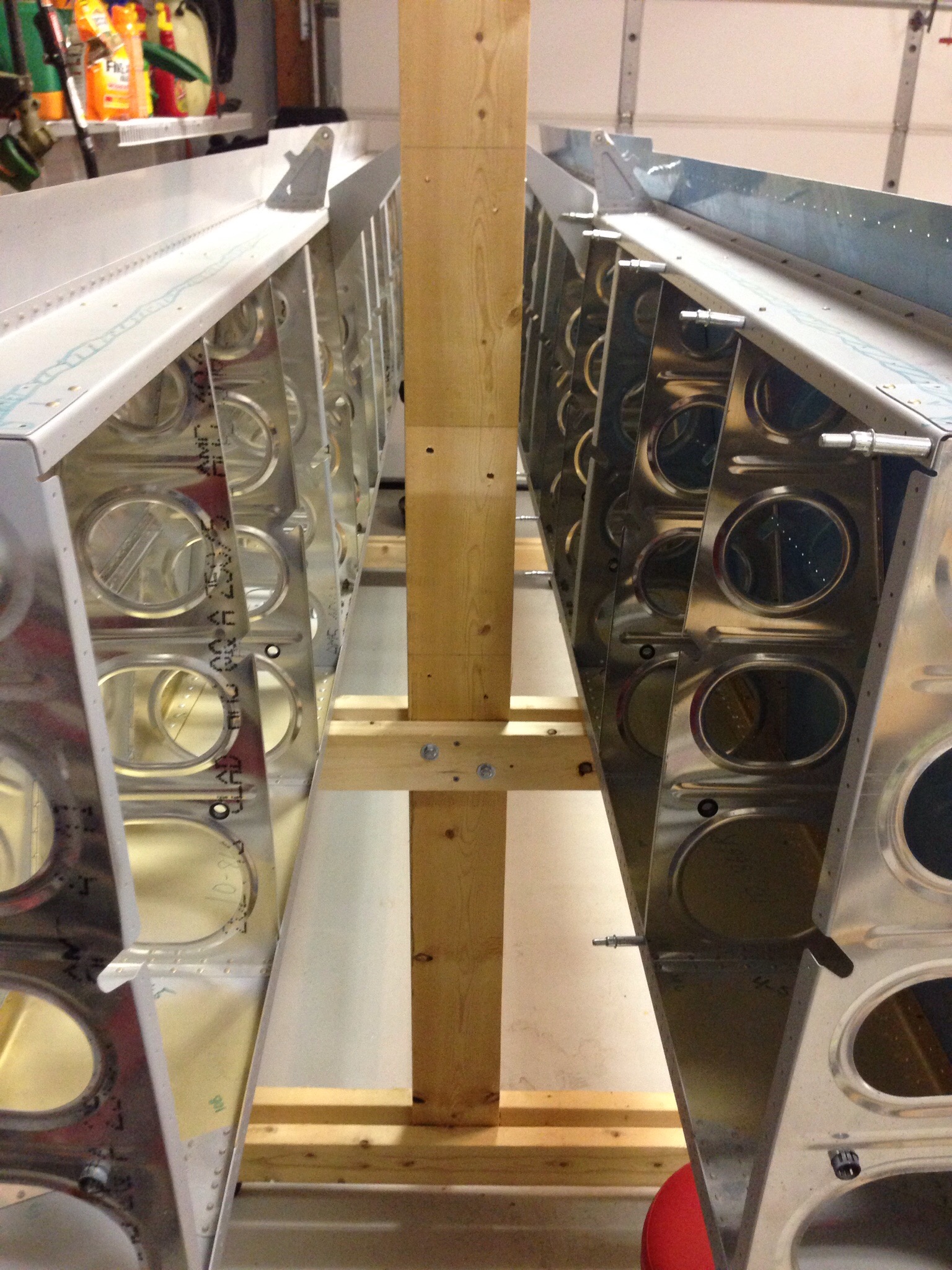
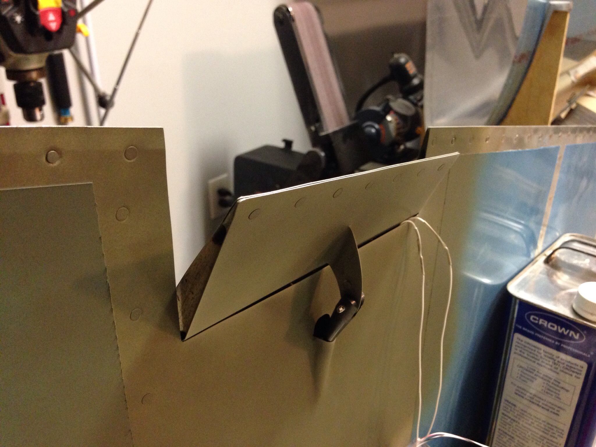
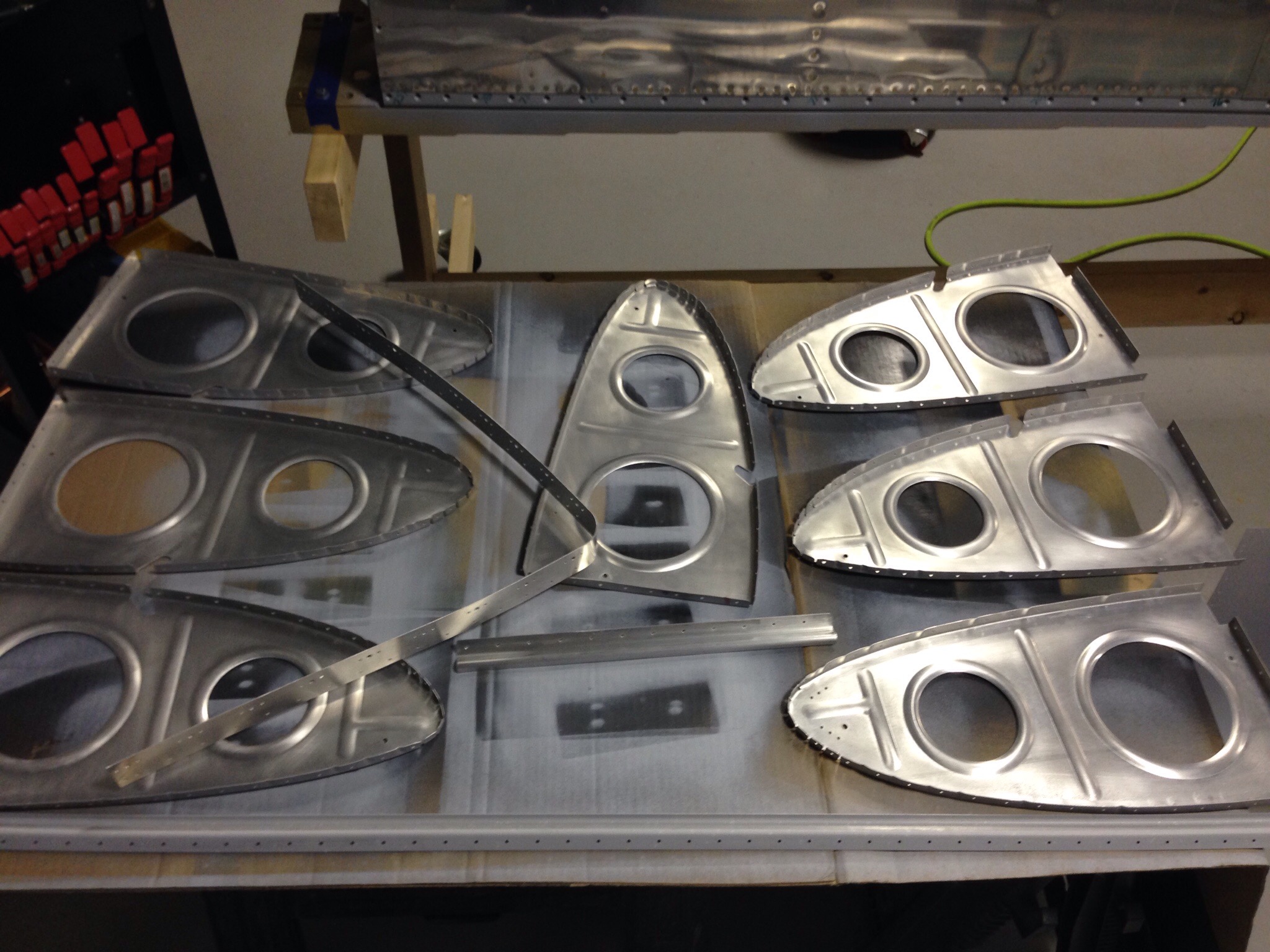
I have decided I don’t like leading edges. While they are beautiful and shapley, not to mention aerodynamically critical, they are a real pain in the ass to build. The real problem are the rib tips and how they just never want to fit right the first, second, and sometimes third time. But with enough patience, perserverance, and hammering (not really, but yes really), they will come together. After assembling and final drilling the components, everything got deburred, primed, and dimpled.
IMG_1456.JPG
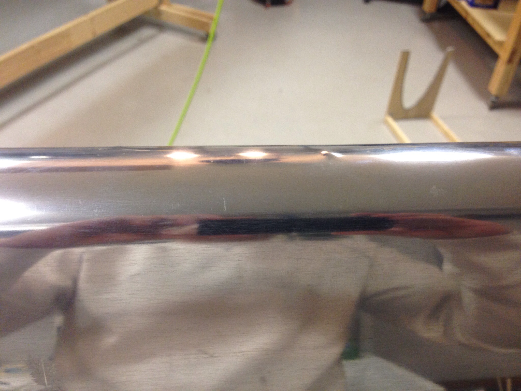
Of course now that I’ve done this four times, I figured out the easiest way to get the skin to wrap around the ribs is to start on the flat side, then work from end to the other around the profile of the skin. I also had the first “F**k-up” that will be a lasting oops on the project. I managed to drop the bucking bar and it seemingly bounced around the inside of the leading edge before finally dropping right in the bottom with a nice zit on the outside.
It’s not terrible and I was able to very gently hammer a bit back into place. It’ll just remind me that I built the airplane every time I do the preflight!
IMG_1476.JPG
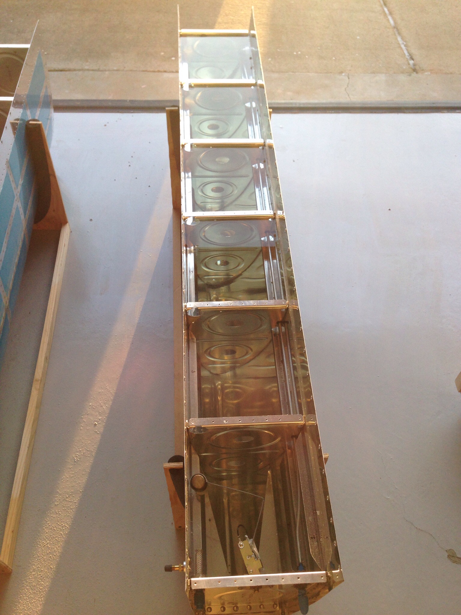
In other bad news, the fuel tanks gave me a 50/50 success rate. The left tank tested fine after the initial fixes cured. Not a single drop of moisture, which made me happy. This was confirmed after four days of water sitting in the tank.
IMG_1460.JPG
The right tank wasn’t done fighting. The one rivet on the fuel cap flange continued to drip like I hadn’t even attempted to fix it. And the rather large leak on the front spar continued to leak, albeit a bit slower and farther out on the spar proving I didn’t really fix it but just slowed the exit path. So, again it was drained of 30 gallons of water down the driveway and dried out to prep another fix session. For now, here is the completed bits of the left wing.

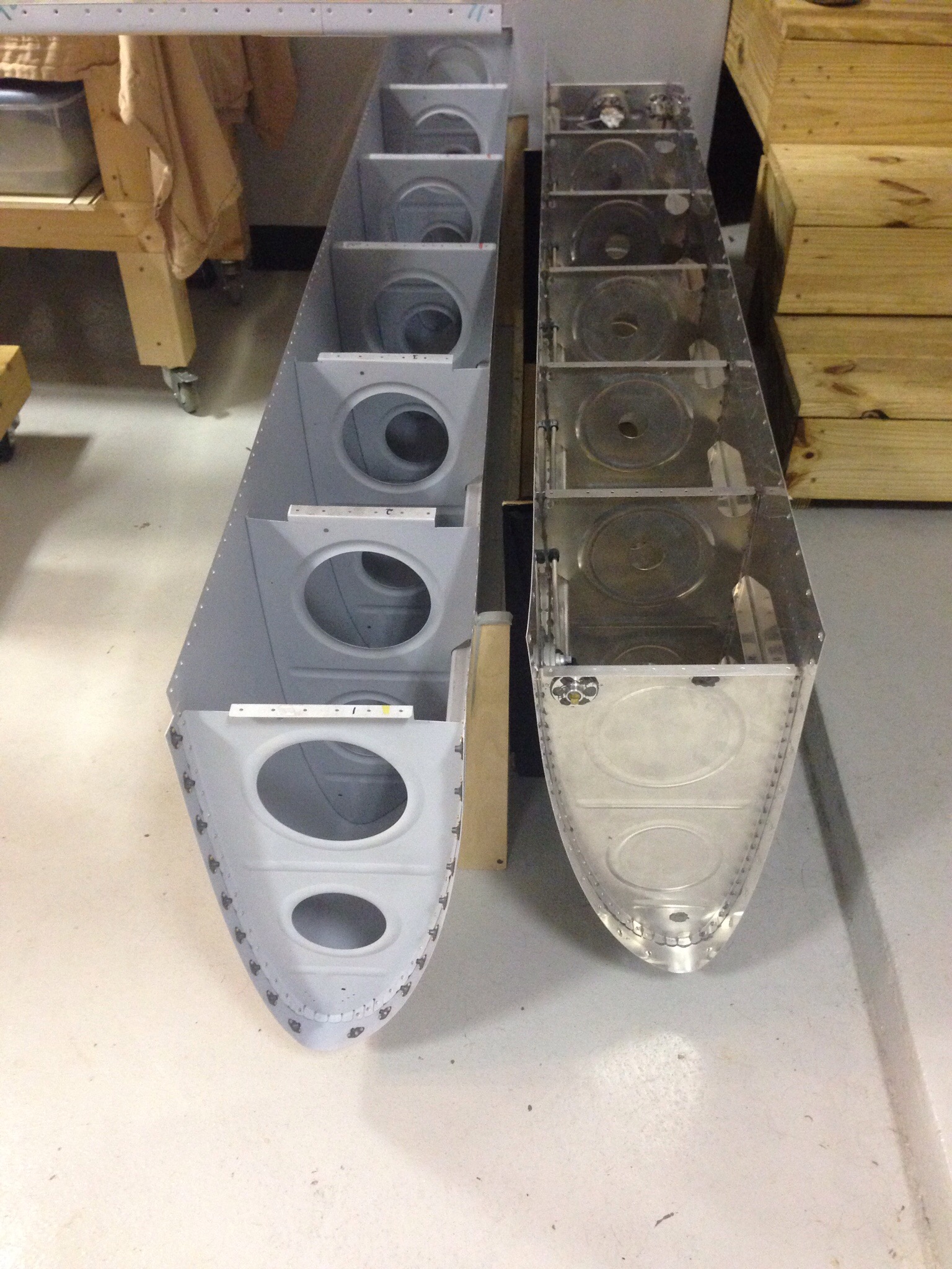
IMG_1479.JPG

Ah yes, that’s what it’s called…progress

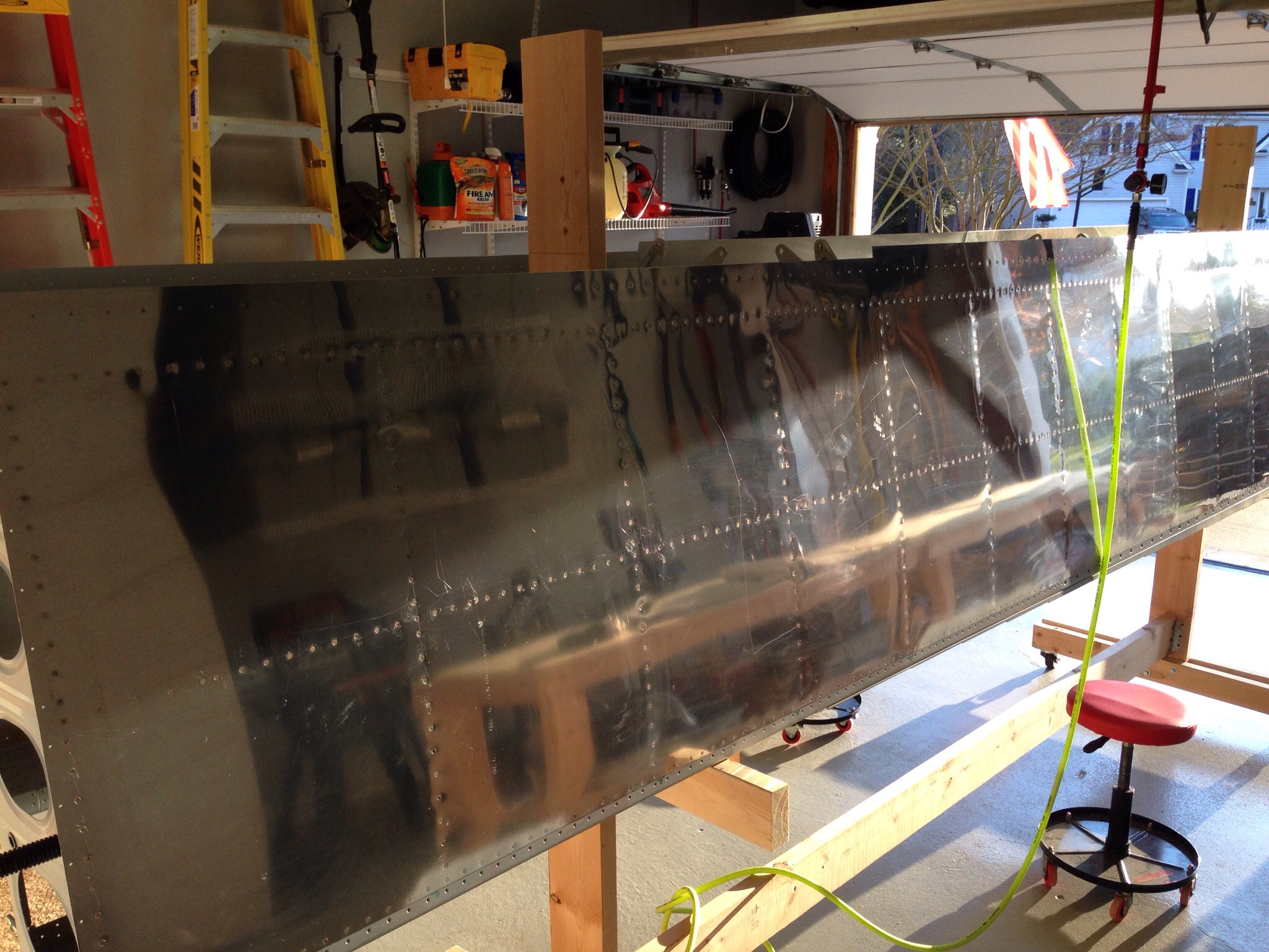
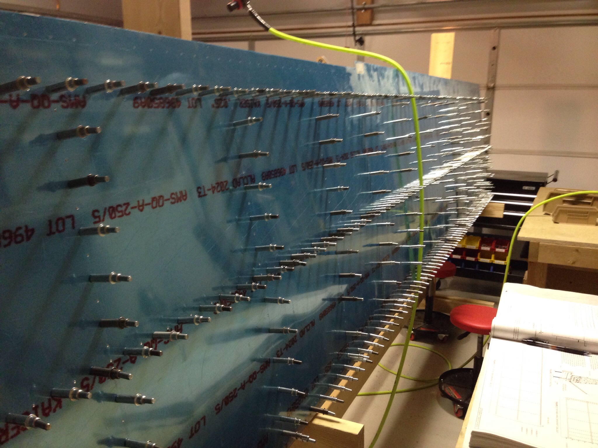
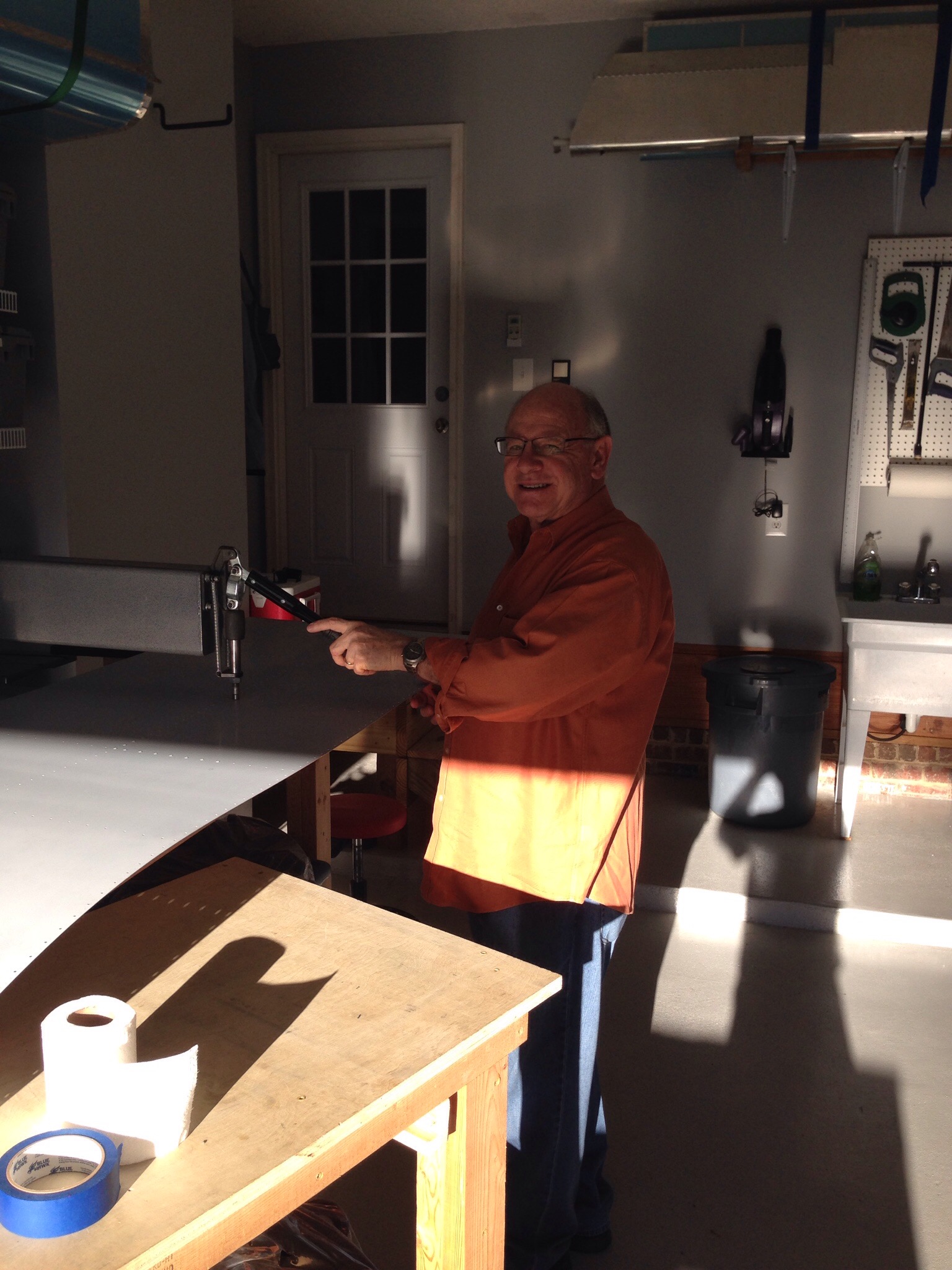
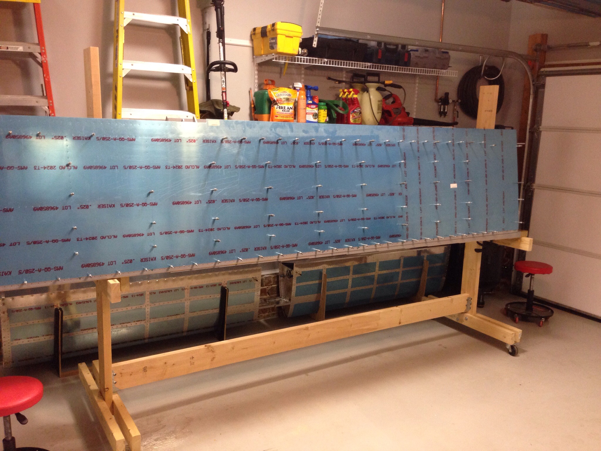
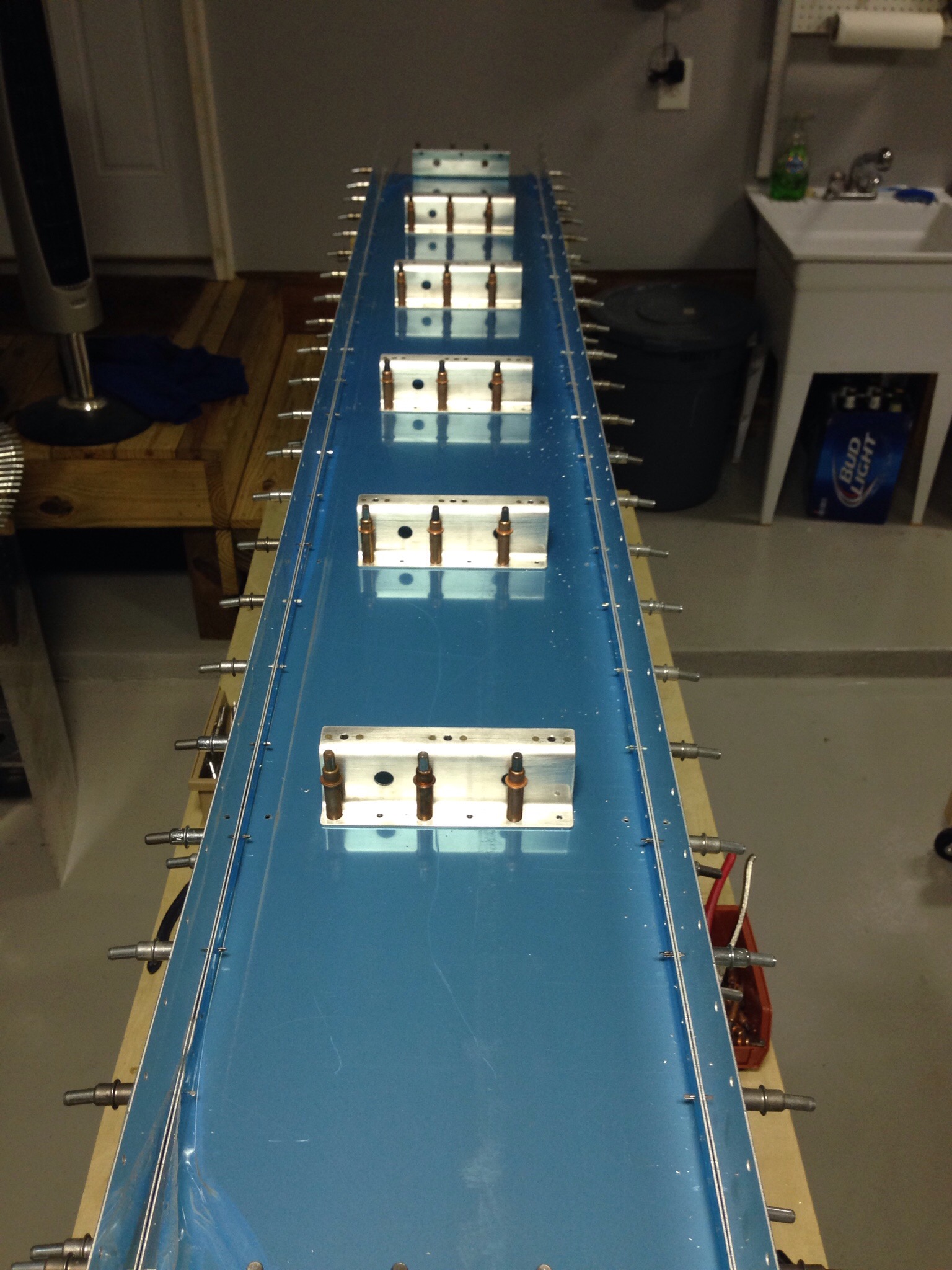
It seems like progress appears in spurts with these types of builds. And this is one of those spurts! I finished riveting the top wing skin with the help of my dad and wife over the course of a couple of days. All went well and I’m now much more comfortable with the rigidity of the wing hanging on the rack.

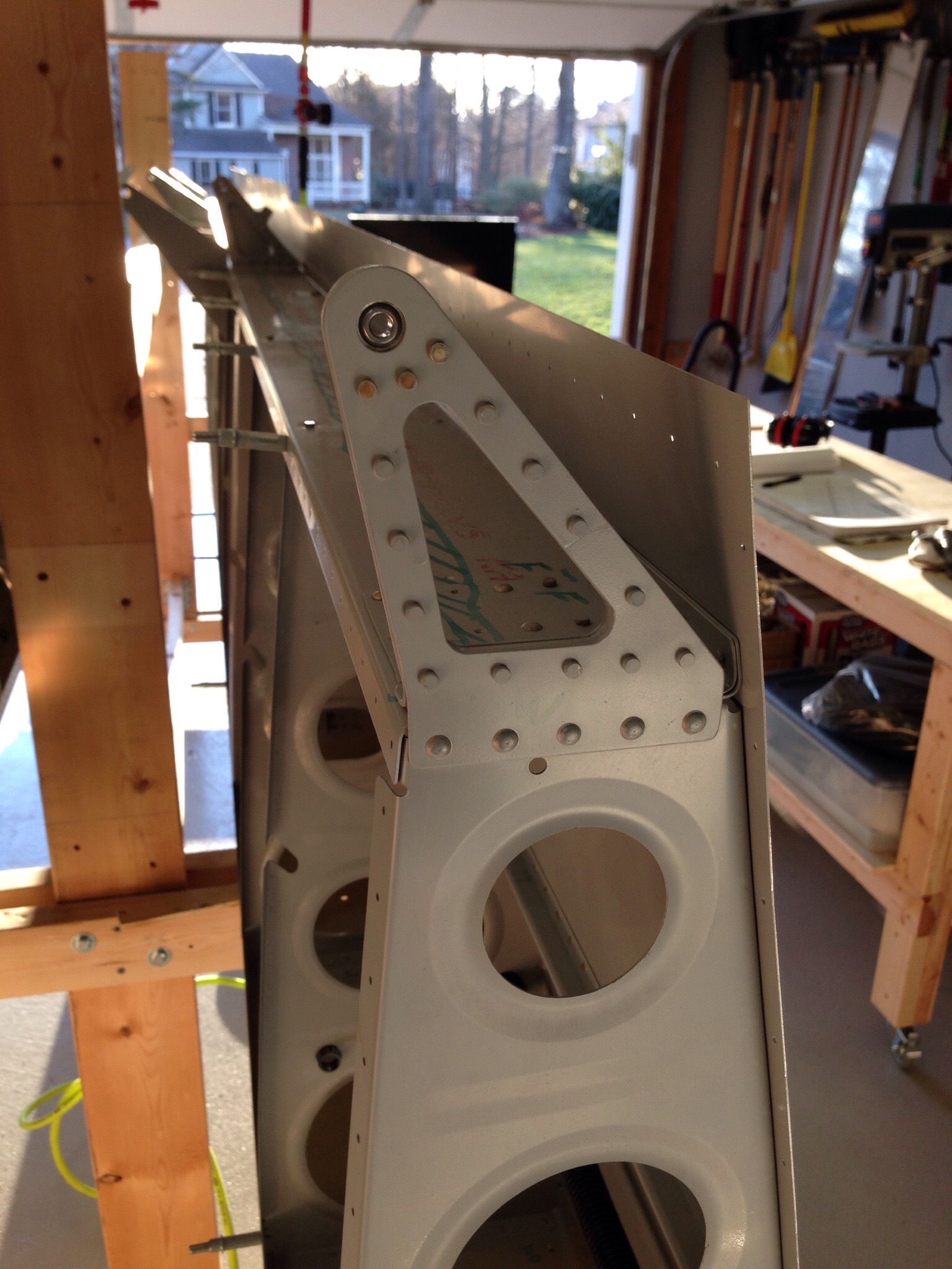
IMG_1452.JPGI also attached the outboard aileron brackets on each wing per the plans. My random parts tub is quickly emptying out for the wing kit, which is a good thing.

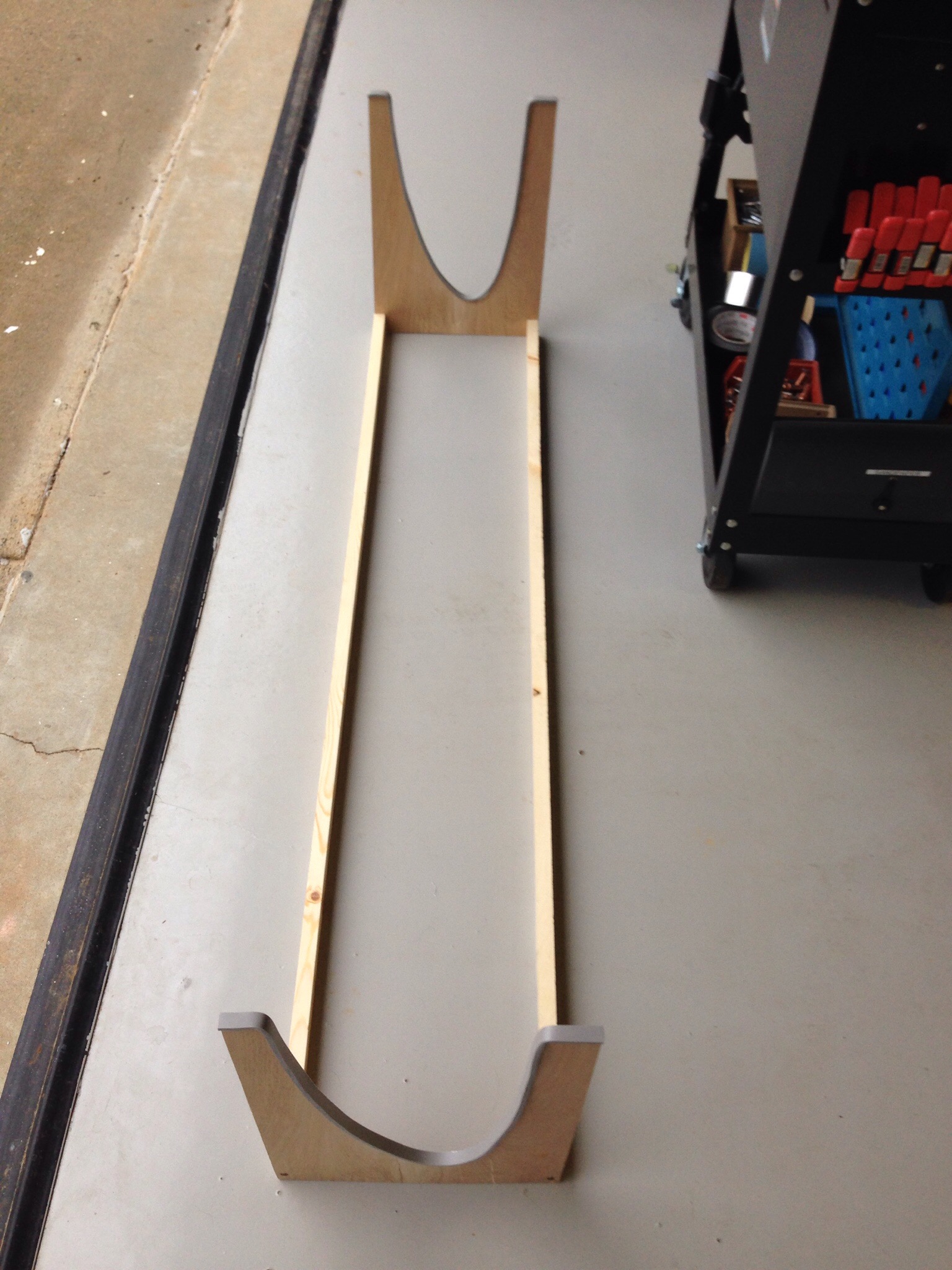
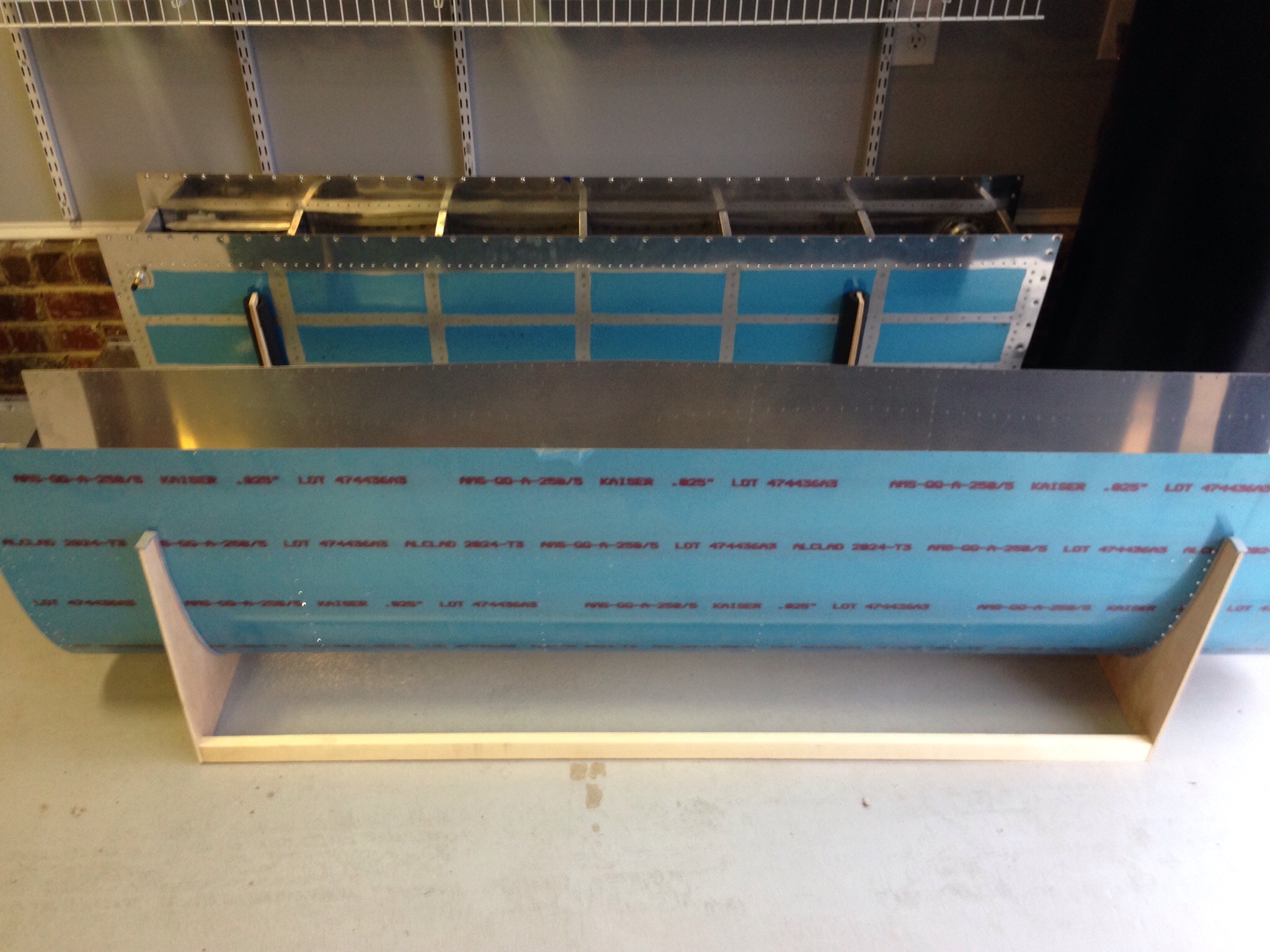
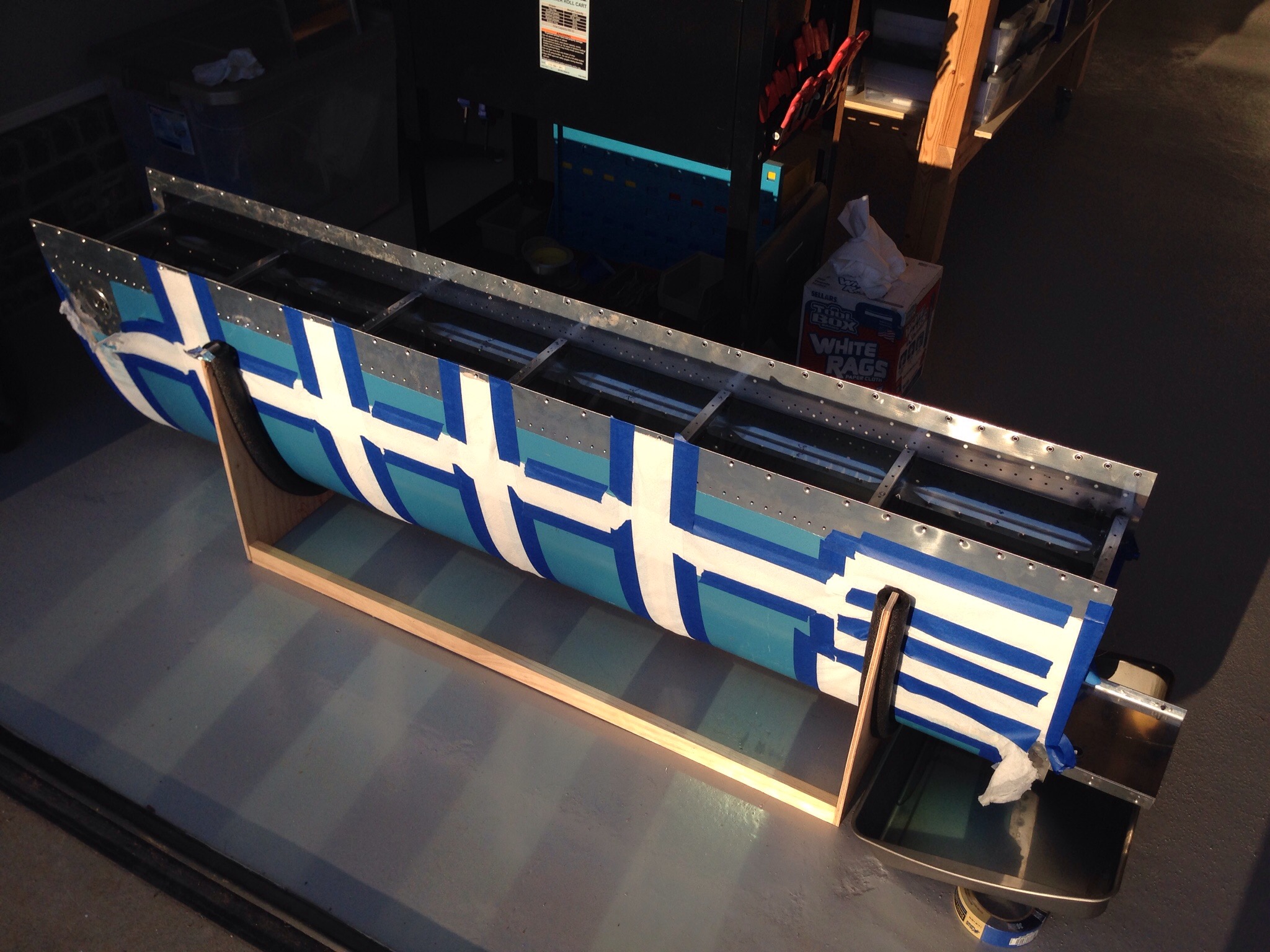
IMG_1451.JPGNext up while the tanks finish curing with the fixes are the leading edges. Normally these are done before the tanks, but it doesn’t really matter as long as they are bolted on the wing spar in the correct order. I went about doing woodwork again to create cradles for the leading edges. A quick job and hopefully won’t be needed as long as the tank cradles have been.

IMG_1453.JPG

IMG_1454.JPG

Leaking…I mean Testing…the tanks

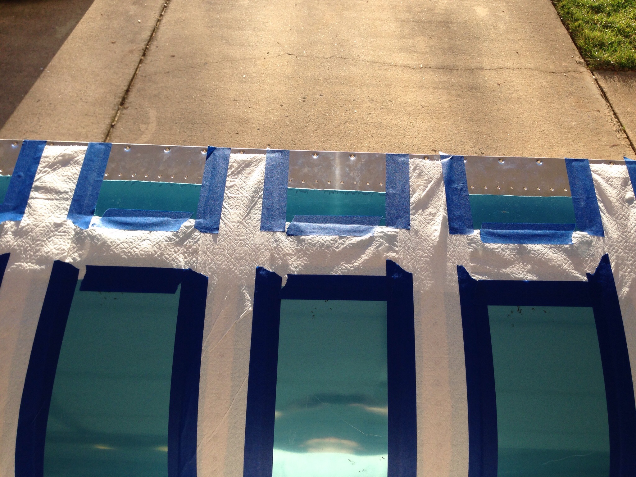
You can guess how it went by the title. I read another build log and saw the idea of testing the tanks before sealing the rear baffle in with water and food coloring. The guy had taped toilet paper on all the seams to be able to identify weeping rivets / leaking joints. I decided that was a good idea since I’m not in a hurry and it would allow me to fix any spots with Pro-seal instead of having to tear into the sealed tanks.

IMG_1427.JPG
Boy am I glad I did this.

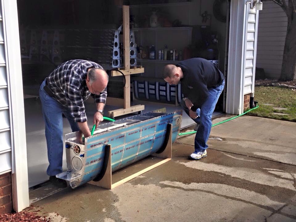
My dad and I got out the hose and filled up the right tank first. Overall, I’m really happy with my first Pro-seal job. I had one weeping rivet (a solid, steady drip) at the fuel cap flange and a stead little stream at the seam between the front spar and skin. After a little inspection, I think I can see where I didn’t get a complete fillet on that joint, so I’m confident it will be a quick fix. I also had one drop appear on the fuel sender plate after letting it sit for 24 hours, so I’ll beef up the Pro-seal on those as well.

IMG_1430.JPG
The toilet paper really wasn’t neccessary, so I didn’t repeat the prep on the left tank. We filled it up and were immediately standing in water. I missed a fillet on the outboard rib and it was a pretty good leak there. I also had one weeping rivet on the bottom leading edge of a middle rib that I’ll need to put some more on.

IMG_1441.JPG
I’m pretty excited that my work was solid and method proven capable. I didn’t use nearly as much as others and my tanks look clean. While I know it wont’ win any awards, it makes me feel better not having the extra mess, weight, and sloppiness inside my tanks. My plan is to fix those few spots after a couple of days of drying and then retest for a few days to ensure they are all set before cleaning and sealing the rear baffles.

Decisions, Decisions

Over the past couple of weeks, I’ve done a lot of work on making decisions based on a lot of research and discussions. This might be a boring read, but I want to document my decisions for the build process and keep my own thoughts straight.

First the engine. It’s a big decision and complicated. I’ve decided to overhaul a used engine and do most of the work myself with the help of a few experienced professionals. There is a local guy who has built many engines for race planes and has a reputable engine shop that has offered to be a technical resource and allow me to use his facilities and equipment. While this won’t be for a while, our hours long conversation has reassured me of this approach vs. buying a new engine. He also advised me on which variants and the things to look for in a run-out or used core. So I’ll be keeping an eye out for good deals on eBay, Barnstormers, etc. over the coming year or so and hopefully make a purchase when the right opportunity comes along.

Building my own engine will also allow me to customize it with the options efficiently and cost effectively. I have committed to running the full EFII electronic ignition and fuel injection system. I like the ease of operation the system provides and most of all, the efficiency of the system. I will use the dual ECU option to provide redundancy for IFR operation. Combined with the Show Planes cowl, Flightline AC system, and possibly a horizontal induction pan, there will be some modifications required for sure. But this will be the airplane that I want and an efficient, modern platform.

It will also be heavily electrically dependant. I’m starting on the electrical schematic to include one main battery, one 70 amp alternator, one backup 30 amp alternator, and integrated back up batteries for the EFIS systems. Using the VPX Pro system will integrate my electrical loads with a few exceptions and provide a better insight into the health of the system.

More details to come on all of these decisions, but it paves the way for planning purposes and at least lets me get started on some of the systems side of the build.

Smoothing the skin

Now that the wings are solid on the modified rack, it is time to attack the right wing top skins. I had previously clecoed the skins on the frame to help keep it ridgid, so I added a lot more clecos and started final drilling. It was a lot of drilling and countersinking since the inboard skin and wing walk doublers are countersinked instead of dimpled. No issues here, however, and it went quickly.

IMG_1418.JPG
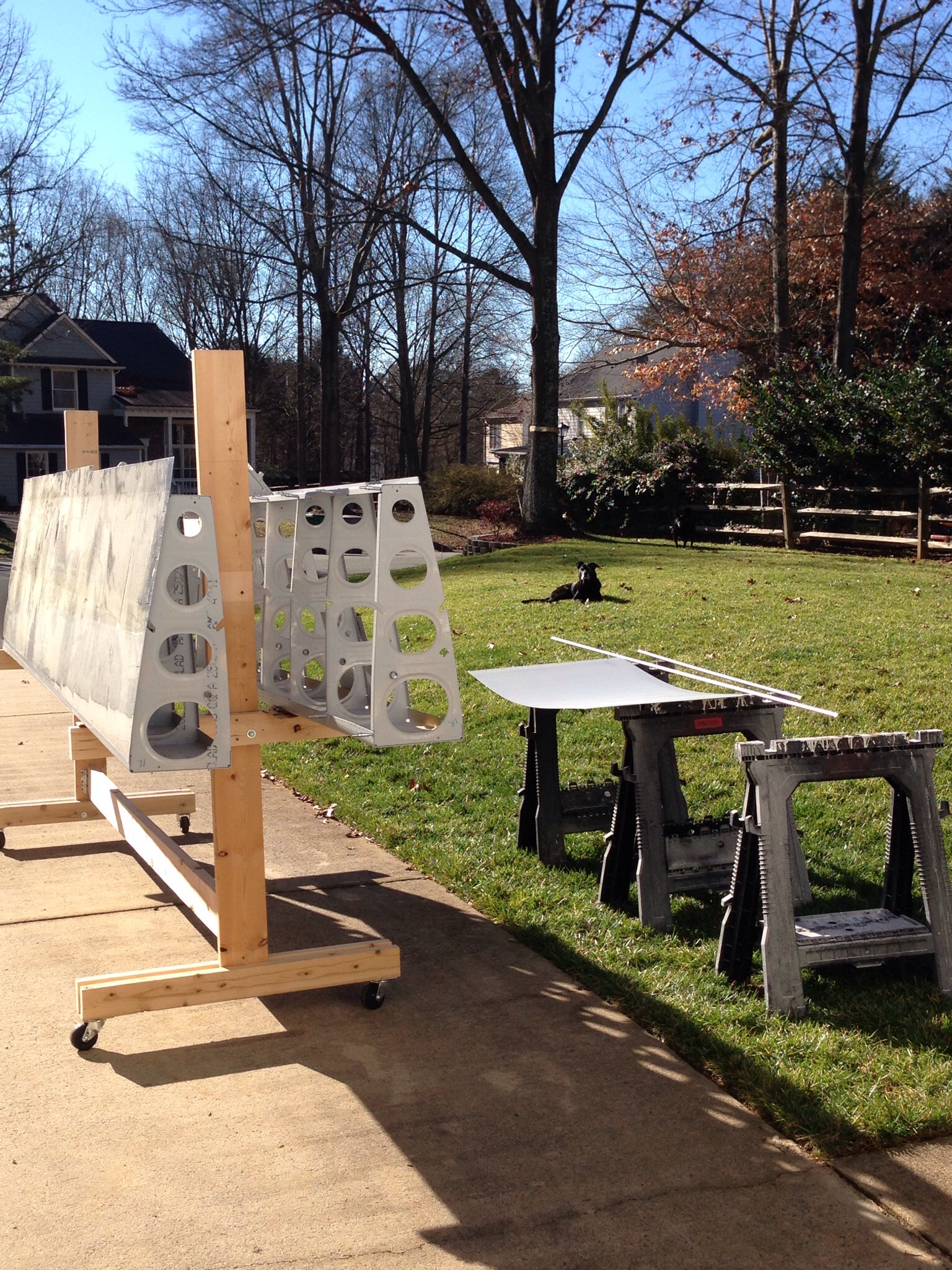
Deburring with the power tool is a breeze and my dad being in town for Christmas lent me a helping hand on the deburring and dimpling. I also got in a couple of cans of the SEM primer in an aerosol can. This is what the original wing builder used and I thought I’d give it a shot. I must admit a like it a lot better than the Dupli-color and may go back to priming everything (I know, I’m so indecisive). It was a nice day, so I rolled everything outside and shot the primer on all the parts, completing the priming of the ribs. I’ll do the left wing when I make it that far. The dogs provided moral support for me.

IMG_1428.JPG

IMG_1426.JPG

Control Approach to my rudder pedals

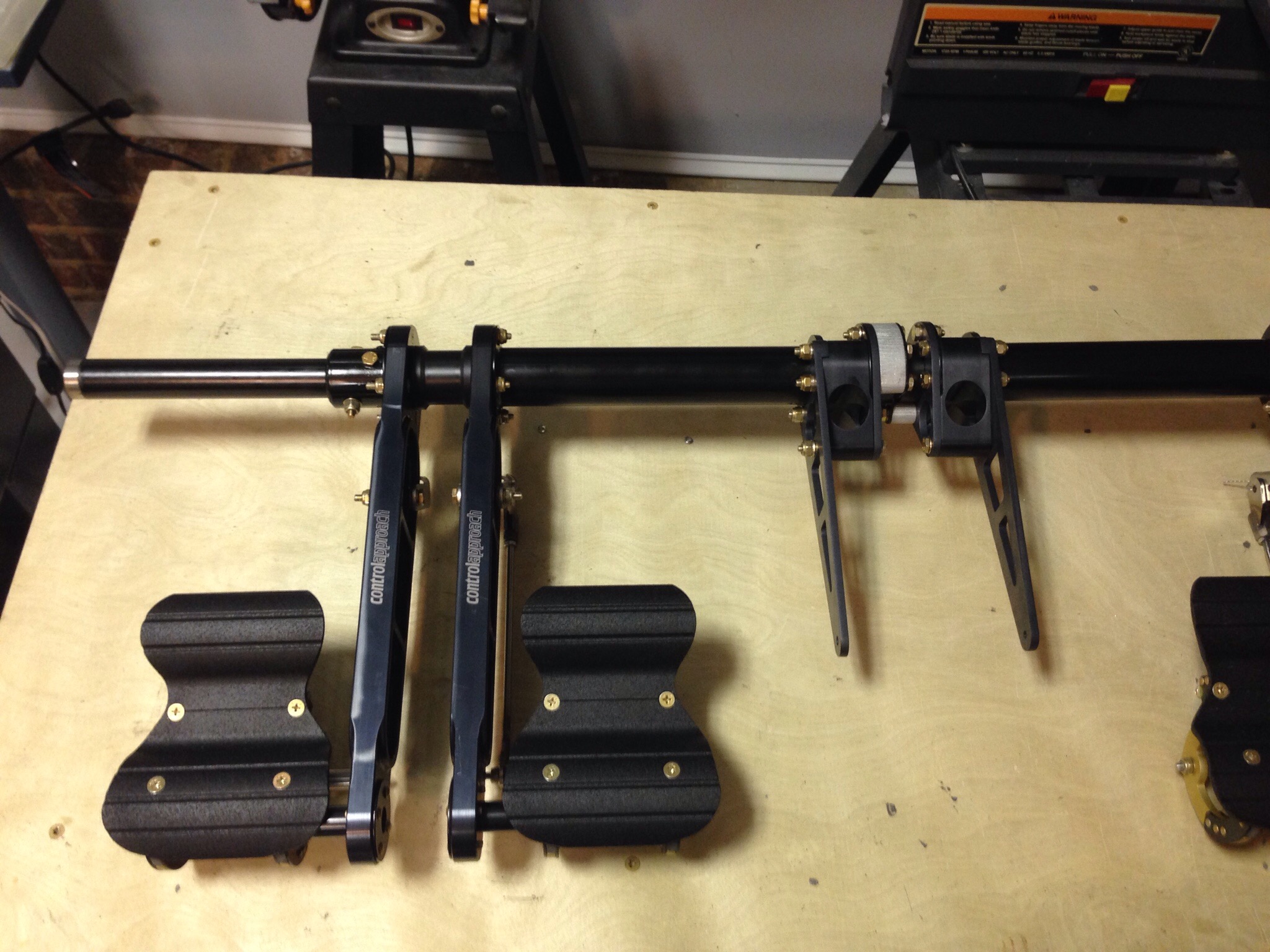
RV-10 builders have drooled for years over ControlApproach rudder pedal set up and I am no exception. A few lucky guys picked up the available sets and Paul hasn’t produced them for a couple of years. I always kept an eye out for the classifieds for a set but had no luck. I decided to take matters into my own hands and reach out to Paul directly.

As luck would have it, Paul was filling promises and had a small production run with one set left. I weaseled my way onto the list and within a few days, had a set on its way to my house.

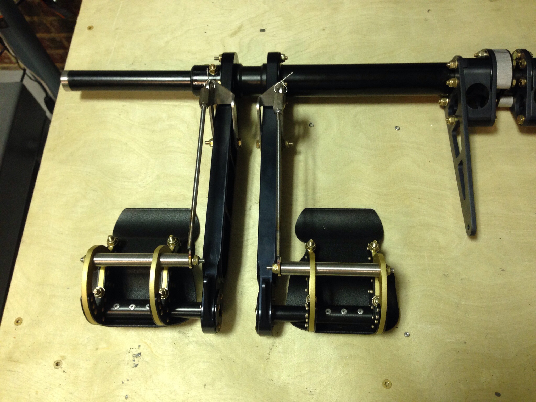
These pedals first of all look amazing. The design is much better aesthetically then the Van’s setup and goes along way to making the aircraft interior look professionally done. They are also awesome functionally, feeling much better (in my limited experience, one flight with and one flight without them) especially with the free-castering nose wheel on the 10. They relocate the master cylinders to the back of the pedal arms to clear up some foot space and eliminate hitting them with your shoes. They also move the rudder cables to the tunnel for their entire run.

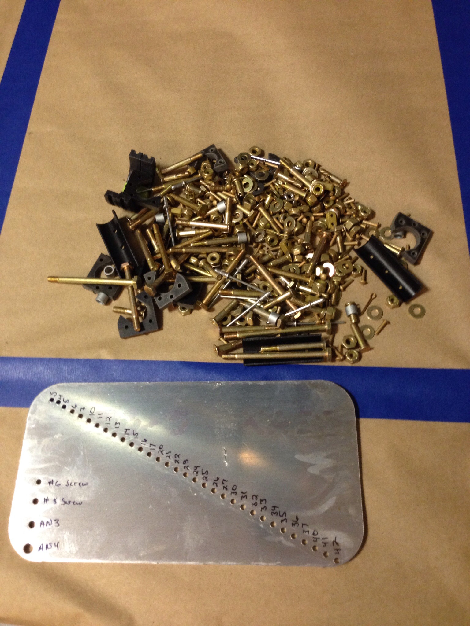
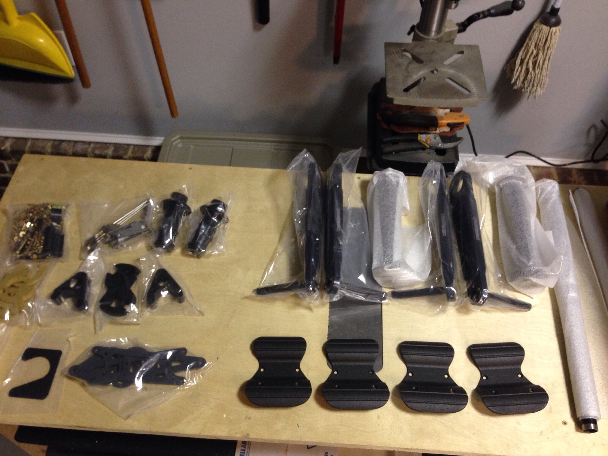
While the machining and quality of the pieces is amazing, the directions leave a lot to the imagine. The box was well packed but the hardware bag was a bit intimidating!

IMG_1419.JPG
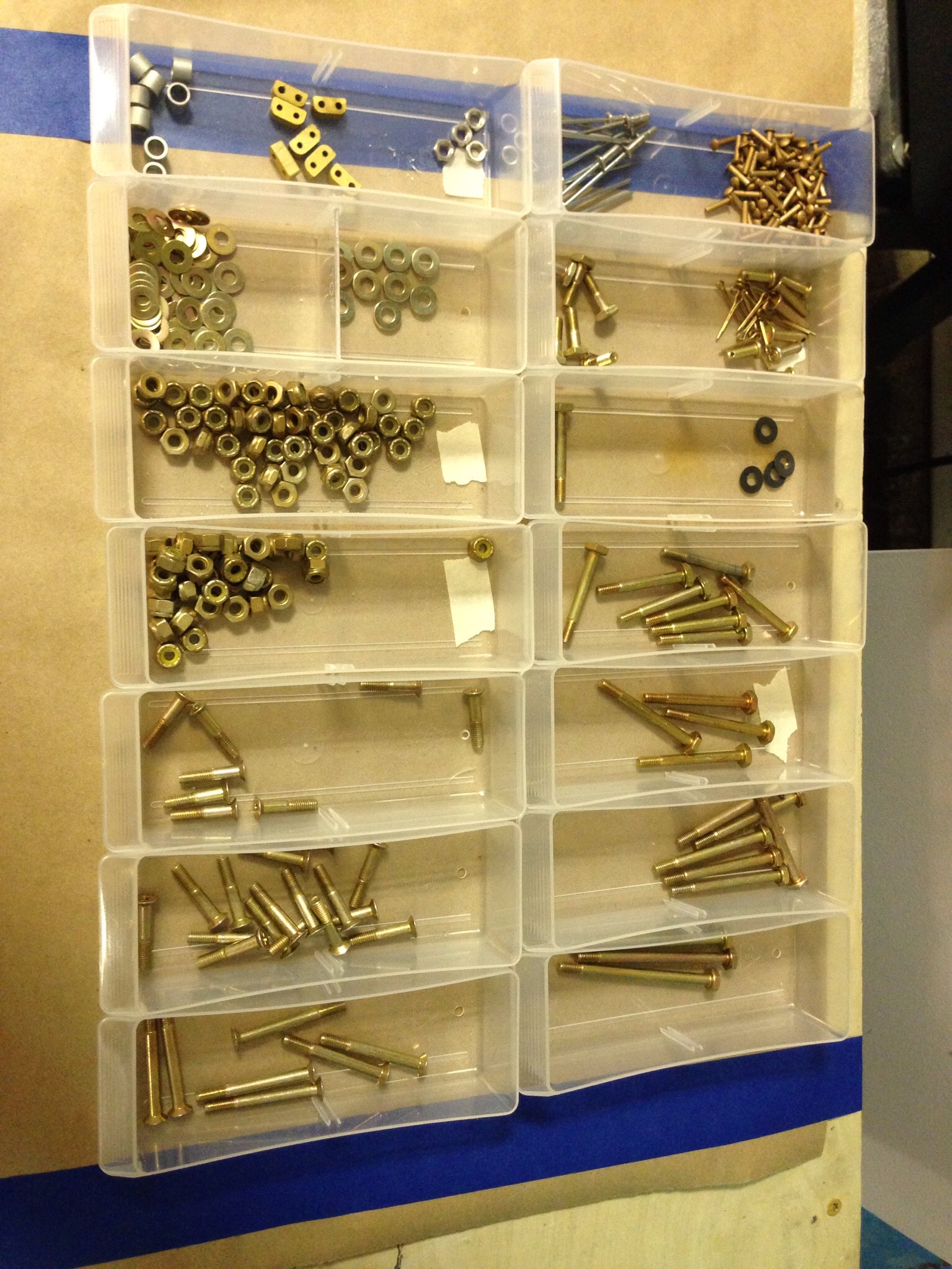
After a bit of organizing, it was much less messy and I was ready to get to work.

IMG_1420.JPG

IMG_1416.JPG
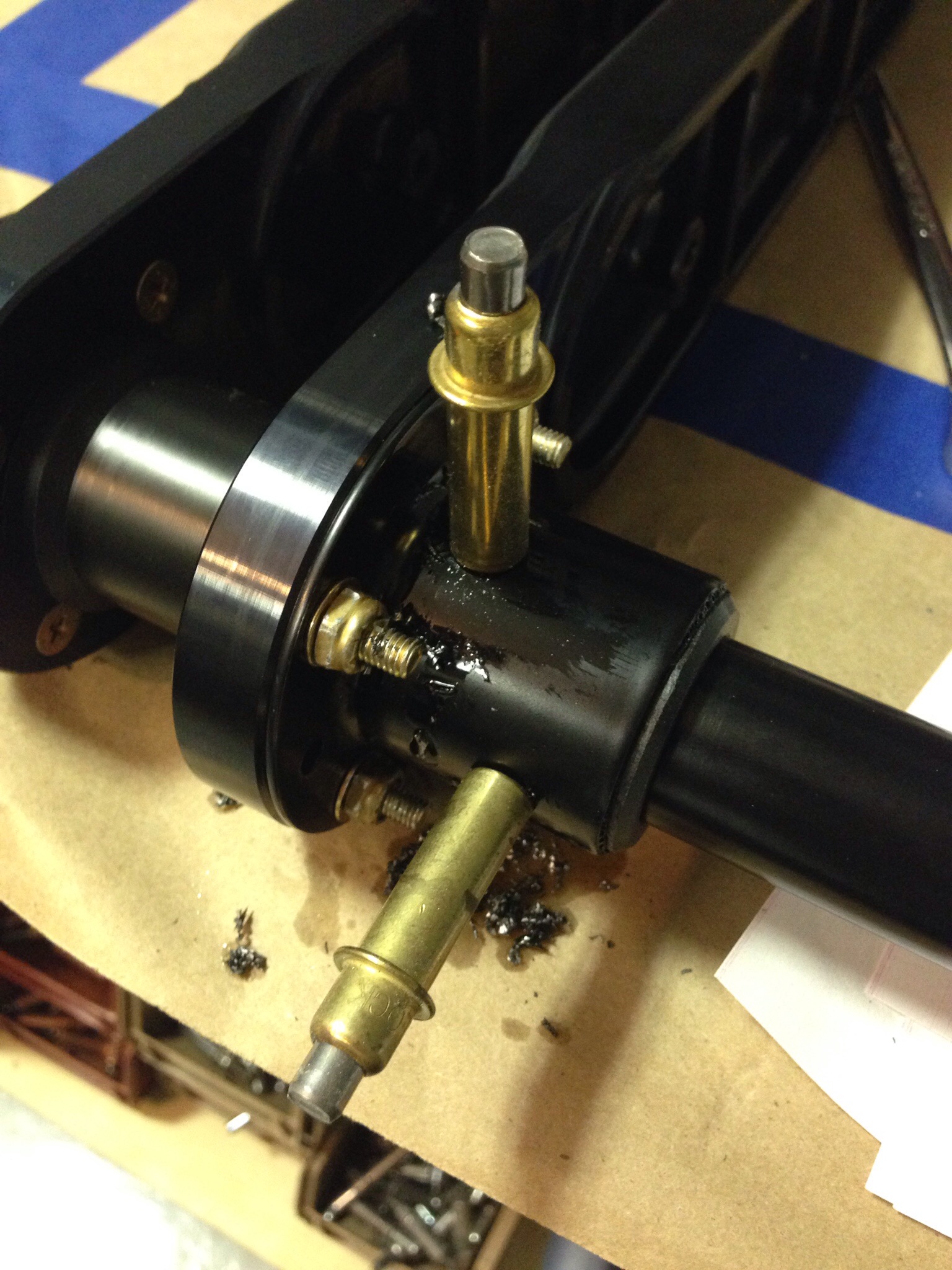
I had to re-read the directions a lot, but once I got a start and all the pieces laid out, it makes sense. A bit of jigging was required to get the four holes drilled for the inner and outer tubes that linked the pilot and copilot pedals.

IMG_1421.JPG
There is also a shortage of thin washers with the hardware kit, but I fortunately have plenty in reserve and most that I need are needed when installing the master cyclinders. I put everything together and securely stashed them away in the storage racks until ready for the fuse.

IMG_1425.JPG

IMG_1424.JPG

Wing Re-Rack

While both fuel tanks cure, I shifted my focus back to the wings. The first problem I wanted to solve was my wing rack. While it’s a nice storage solution to keep the wings safe and out of the way, I quickly saw that it was keeping the spars in a warped state due to the way it was hanging. So I disassembled the frame and decided to shorten it, allowing the spars to sit on top of two cross pieces. This would allow me to better square the wing and secure it a little better while putting it in a better position to work on it. I’m much happier with the result now, as it’s more of a work platform and a storage solution. I’ll also be able to store the wings on it with the leading edges attached with few modifications.

IMG_1415.JPG

IMG_1414.JPG
Then, I completed my wing-walk through. The wing kit was purchased used by me, and being the second builder, I wanted to first understand all the work that went into them and to ensure the work was done correctly and completely. Overall the wings look very good (as I knew at the time of purchase) but there were a few action items.

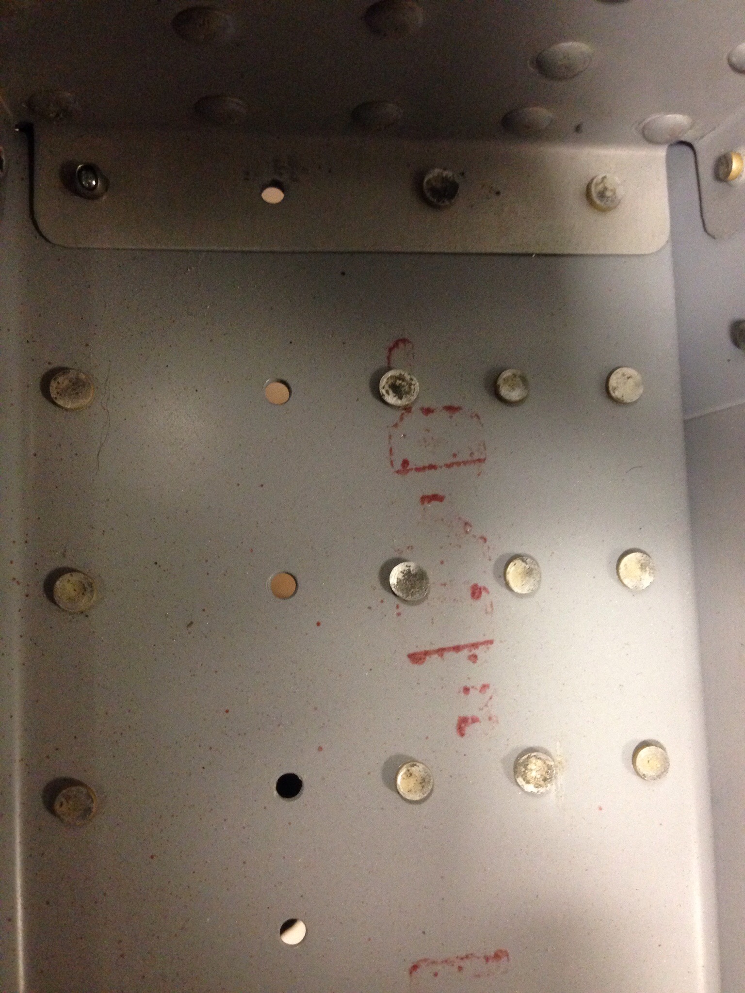
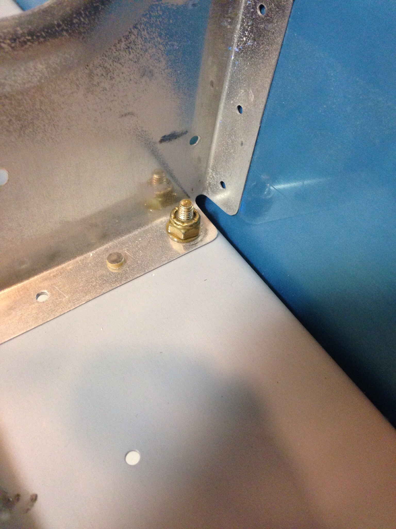
There were about six places on the rib-rear spar intersections that had pop rivets instead of the usual AN round head solid rivets. I still don’t understand why, as it was random and only one per rib. So I drilled those out, cleaned up the holes and installed the rivets according to plans. I had only one hole that was really buggered up, where I couldn’t get any rivet to hold.

IMG_1374.JPG

IMG_1378.JPG
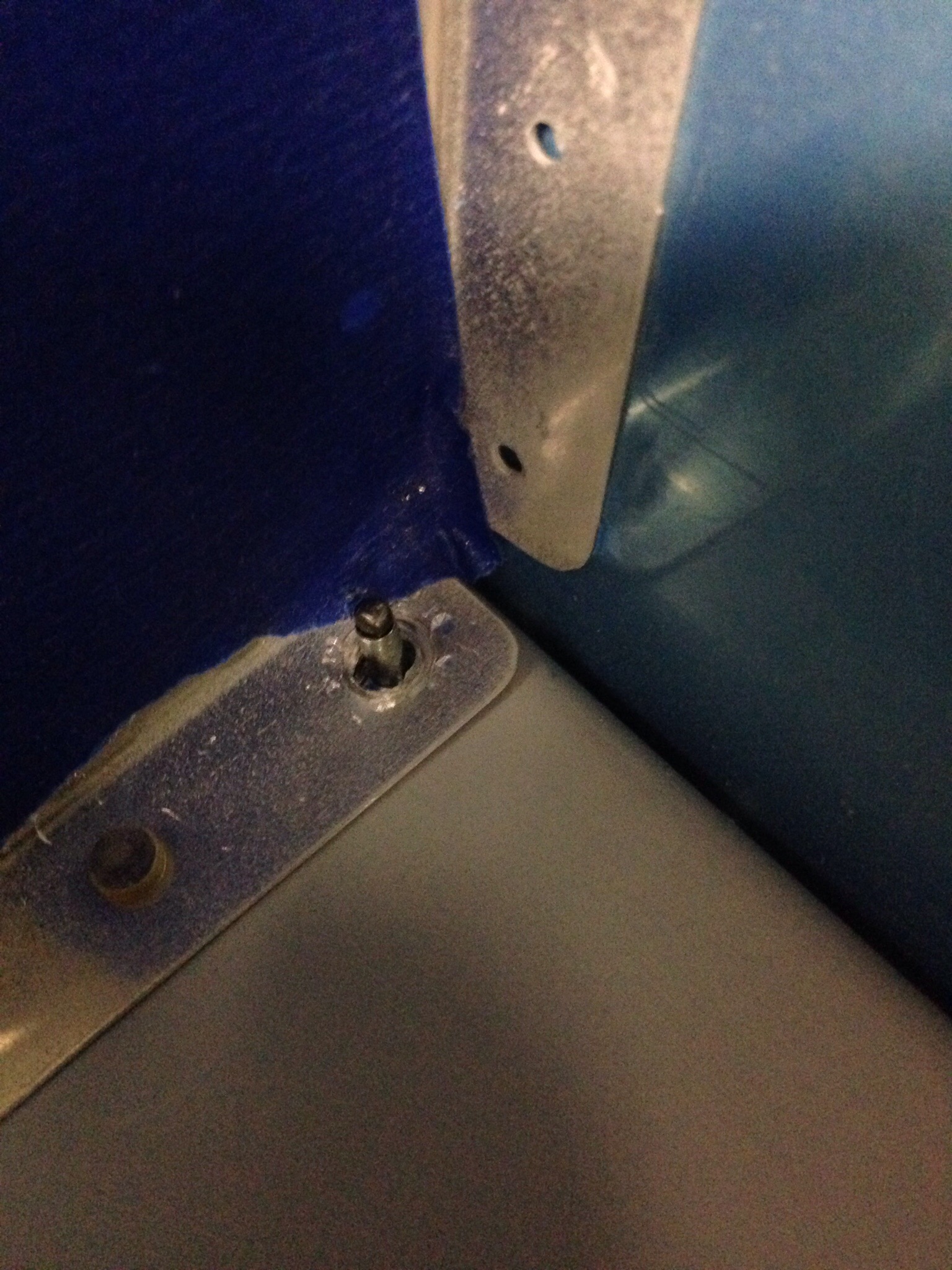
A quick email to Van’s said to drill it out and replace with an AN3 bolt and locknut. It was a simple fix and I know it’s all done right now. Every step was checked off on the plans and it is up to speed for me to take over.

IMG_1412.JPG

Avoiding a sticky situation

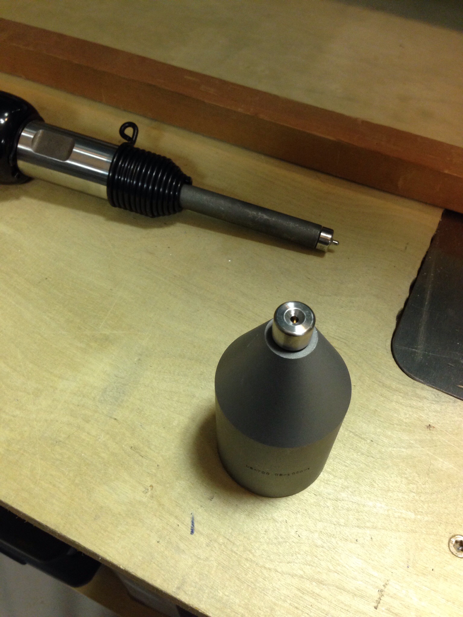
With the drilling and deburring complete, it was time to use yet another new tool that has sat in the toolbox for far too long. This is a bucking bar and rivet set that allows you to insert dimple dies and dimple areas that the c-frame can’t get too. It was useful on the leading edges of the tank skins in the middle of the skin. I did learn, however, that the dies don’t like this tool, especially with a side load on them. I broke two sets of dies. A quick call to Avery and a replacement along with the SafeAir1 pitot mast was on the way.

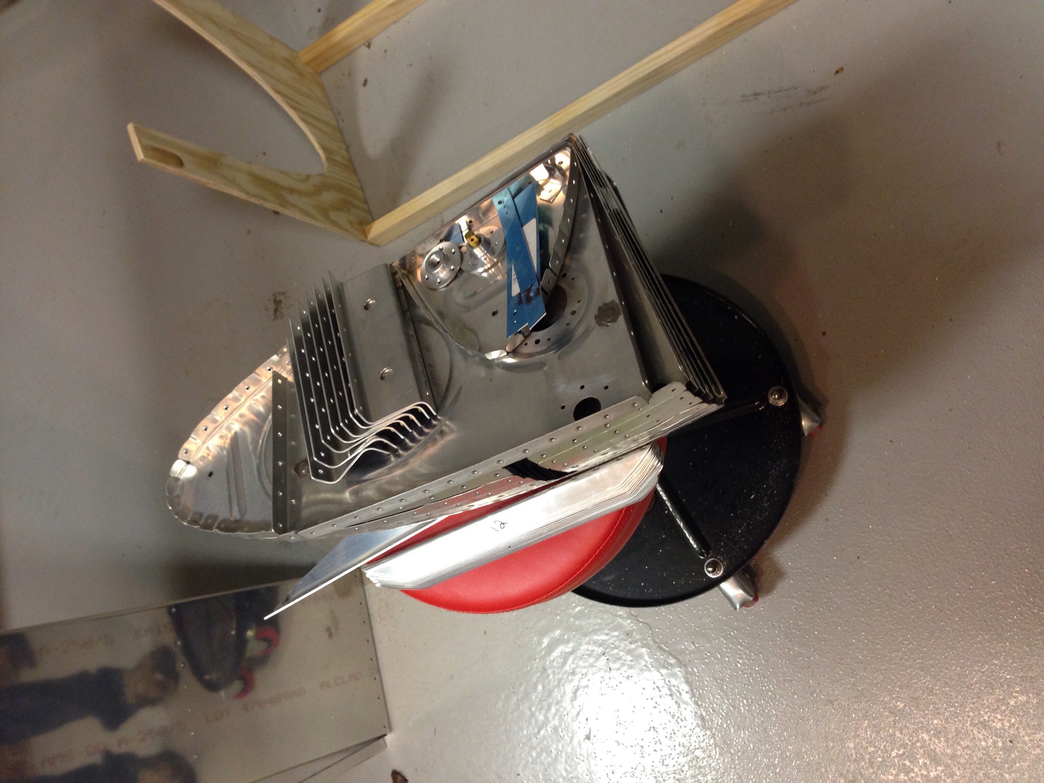
IMG_1355.JPGIt’s hard to believe that almost all the components of the fuel tank can fit on my little stool.  I scuffed the joint surfaces to promote adhesion for the Pro Seal on all the parts. These are all set for final installation into the skin.
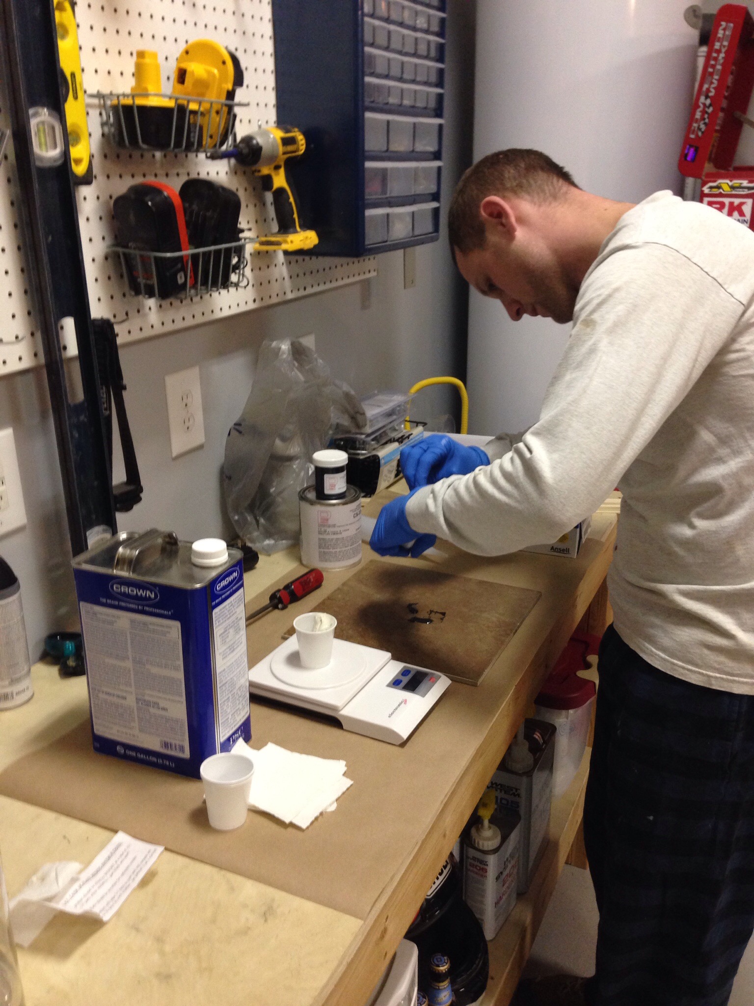
IMG_1359.JPGThis is where things can get sticky. The biggest advice I read was to be prepared for working with Pro Seal and to wear two pairs of gloves while replacing the outer pair often. Once Pro Seal touches a surface, it doesn’t come off without MEK. I used a postage scale to weigh the components, ceramic tile to mix, and the applicator gun from Brown Tool. All that equaled a clean, easy process of using Pro Seal.
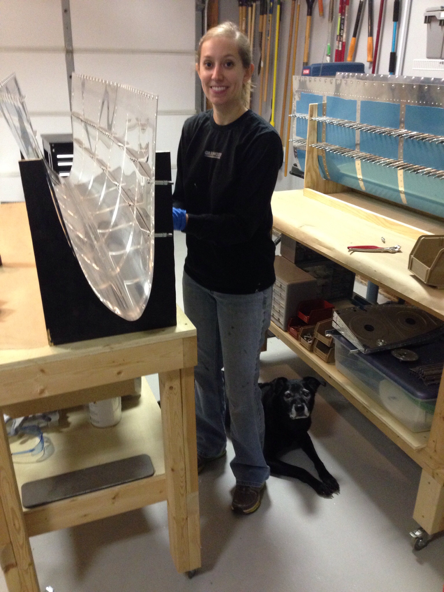
IMG_1365.JPGThe wife-copilot-cobuilder-photographer came out to help and we started with the stiffeners. I chose to 100% cleco the parts in place and come back for riveting the next day. It greatly reduces the mess and actually makes riveting easier. Kayla the flight engineer dog came out to support the project as well. The next day, I came out to rivet the stiffeners with a dab of Pro Seal in each dimple to seal the mfr head of the rivets. Turned out well with the tank die dimple, as it’s a nice flush surface.
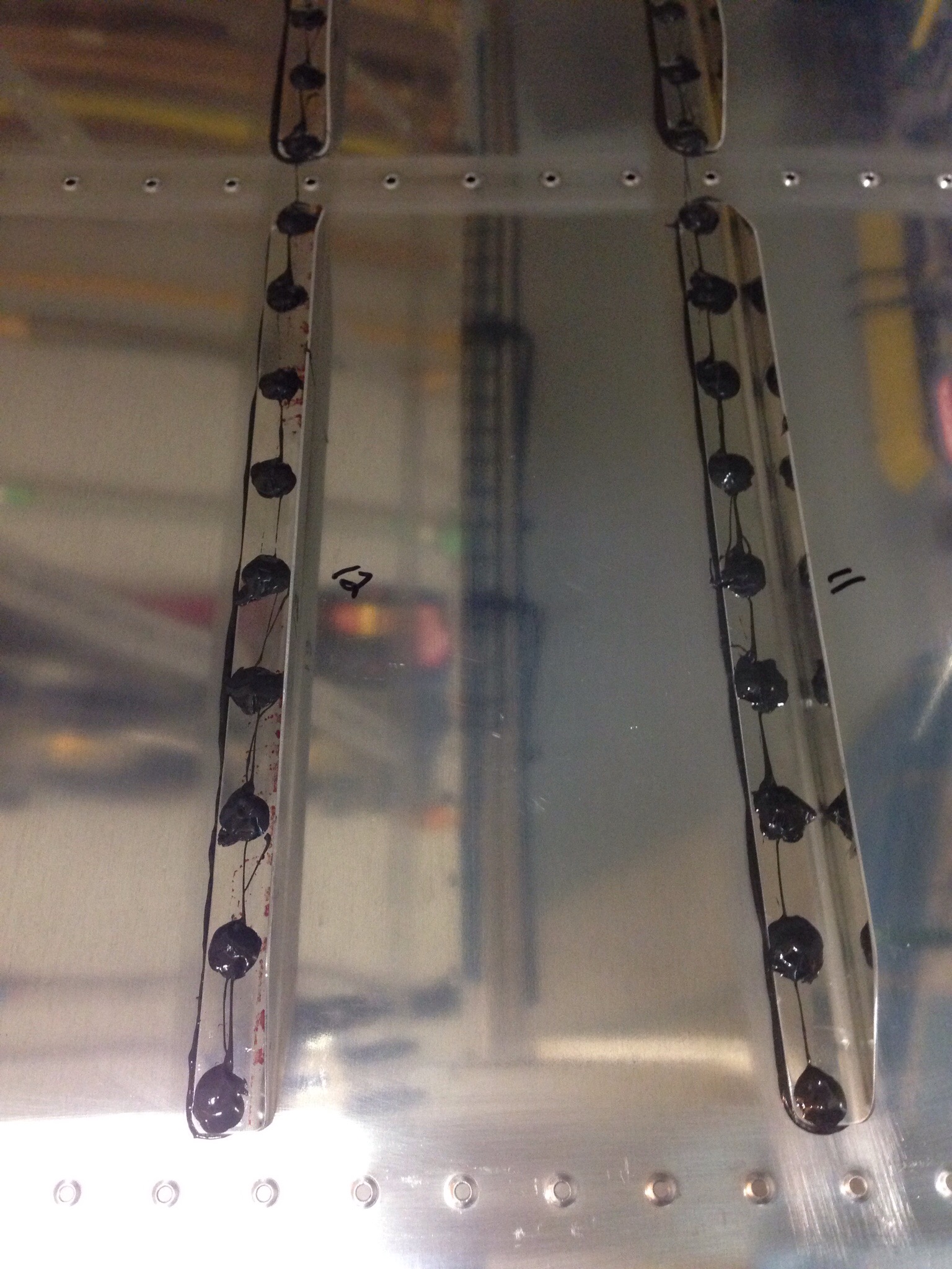
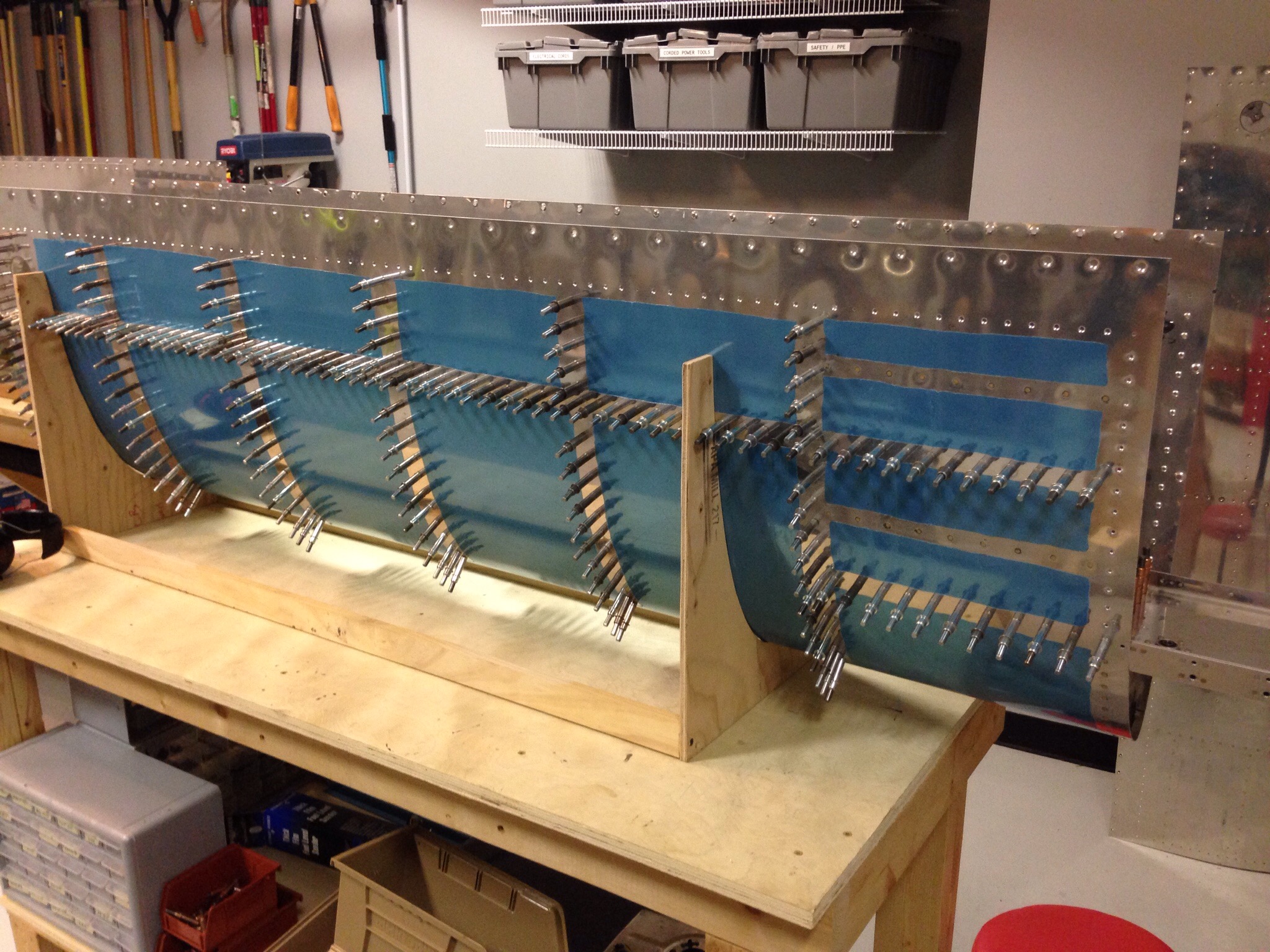
IMG_1375.JPGIMG_1385.JPGI went solo and finished up the ribs and the j-stiffener for each tank after mixing up yet more sticky stuff. I found that letting the sealant cure for one day was perfect for riveting, so the following day was spent riveting the ribs and j channel. I also went back and put a blob of sealant on each shop head, completely sealing each rivet (hopefully) to prevent any fuel seepage.
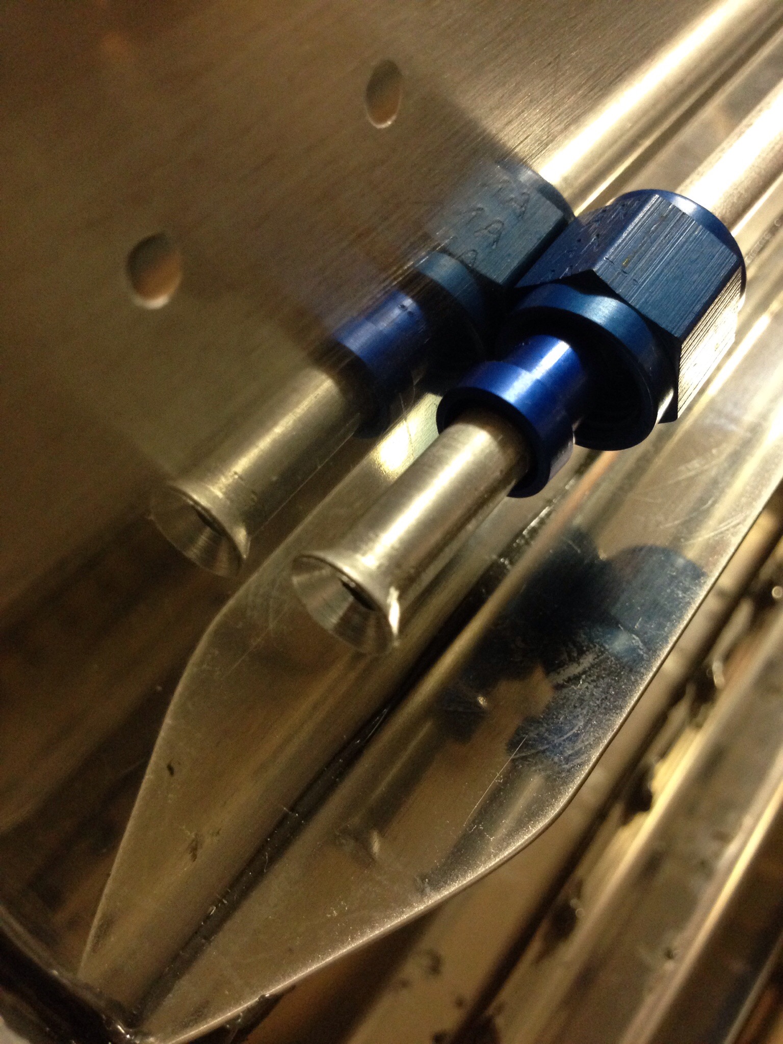
IMG_1386.JPGThe next step is to fabricate the fuel vent lines, which consists of straightening very carefully the aluminum tubing and flaring one end to accept the AN fitting through the end rib. I skipped ahead on the plans and riveted the end rib on before putting the line in, but was able to easily work around it. None the less, it’s a good lesson to stick to the plans. Pro Seal is permanent, so no going back and redoing!
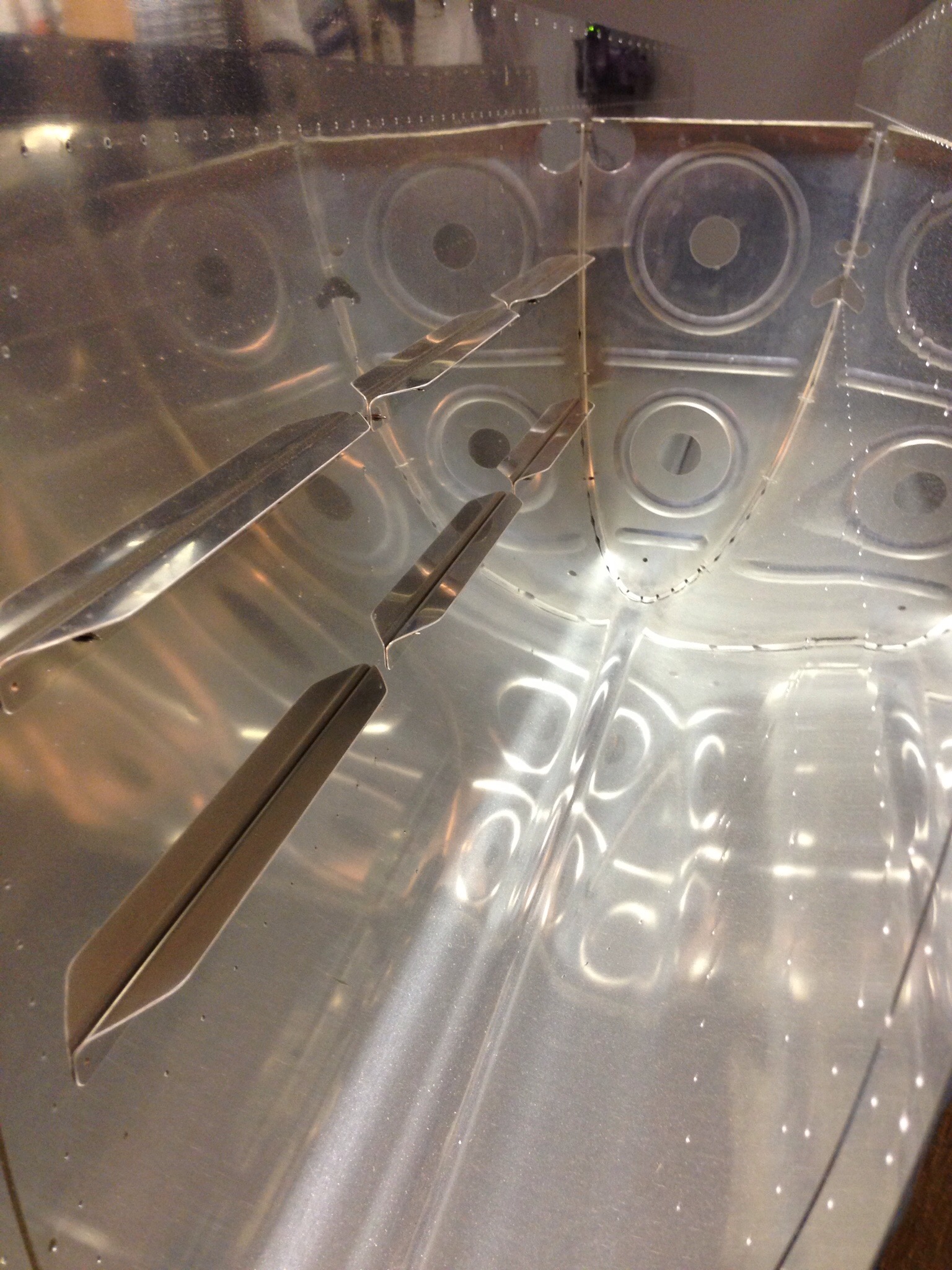
IMG_1392.JPG

We need some gas

With the rudder all finished, it went up in the ceiling with the other finished components to make room on the workbench for the next project.  Fuel tanks are a key part of each build and one that is often dreaded because of the process and mess that it can make.  I’ve read a lot of how-to’s and gotten a lot of advice and feel pretty confident moving into this stage.  I also invested in a few tools that should make the job a little easier, cleaner, and more effective!

First is to prep just like all other steps.  The previous builder of my wing kit started the left fuel tank, getting so far as to seal the ribs and fuel cap flange to the skin.  However, I want to have the upgraded locking caps and wasn’t comfortable with the sealing job that had been done.  So I decided to order replacement parts and start fresh.  I also used the now scrap tank to practice with was helpful.

Each tank has 14 stiffners that are cut from a single stick of aluminum similar to most of the j channels.  Those are cut, shaped, and deburred then match drilled to the skins.  The ribs are also finessed into the skins, especially the pointy part that doesn’t seem to fit well without a little encouragement with the pliers.  I was surprised at how difficult it was to get all the ribs lined up for match drilling.

IMG_0240.JPG

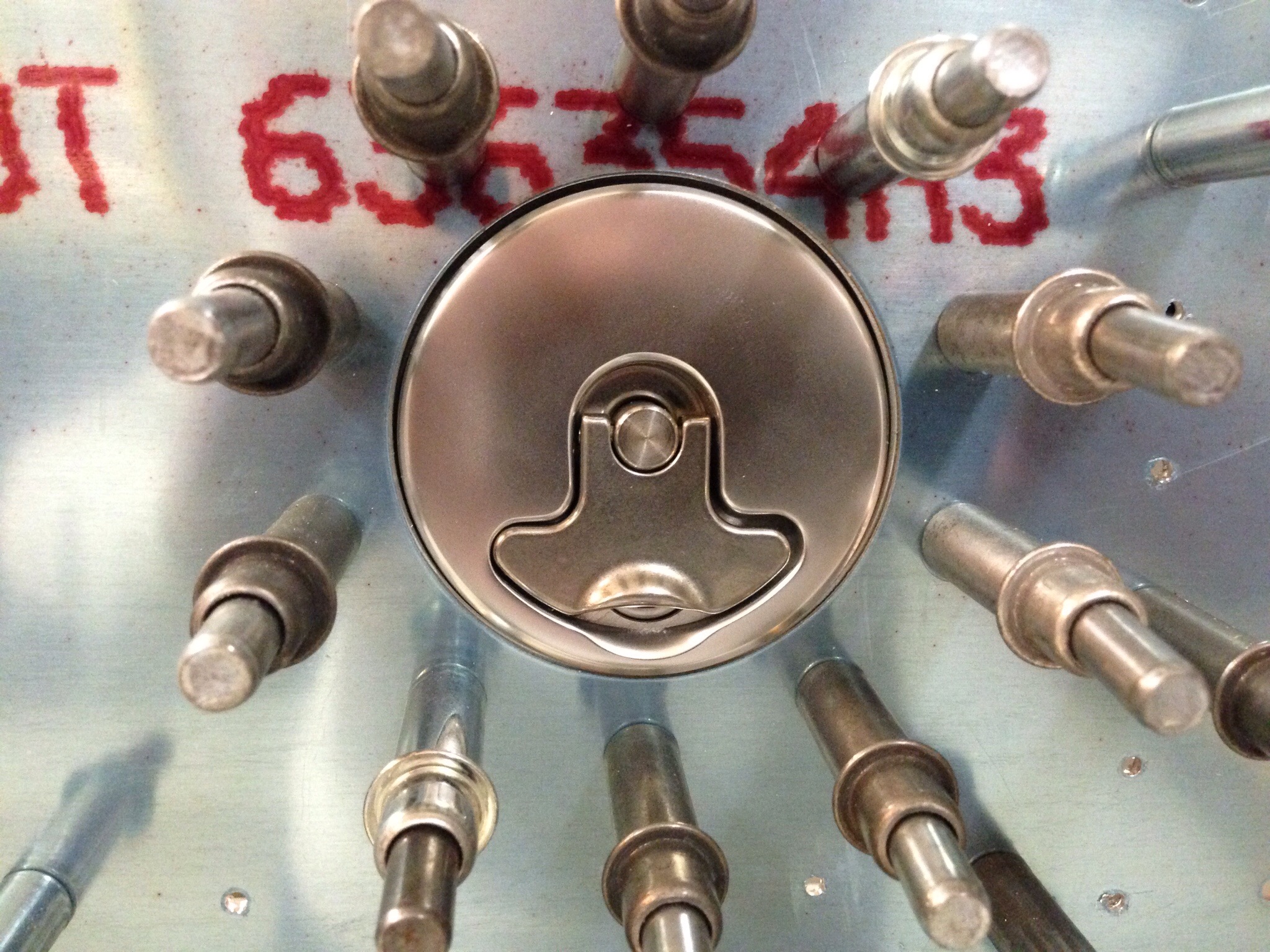
The fuel cap flange is contoured to match the skin.  I used some of the double sided tape for trailing edges to hold it in place for match drilling.  One thing to note is that the locking cap looks a lot better and fits a lot better than the stock Van’s unit.  Well worth the extra money for me.

IMG_0311.JPG

The attache zee’s were next, having been match drilled to the tank spar and having nut plates installed.  These will be primed as will the exterior of the tank ribs.  Nothing inside is primed, as the fuel is corrosive to all but the mightiest of paints.

IMG_0313.JPG

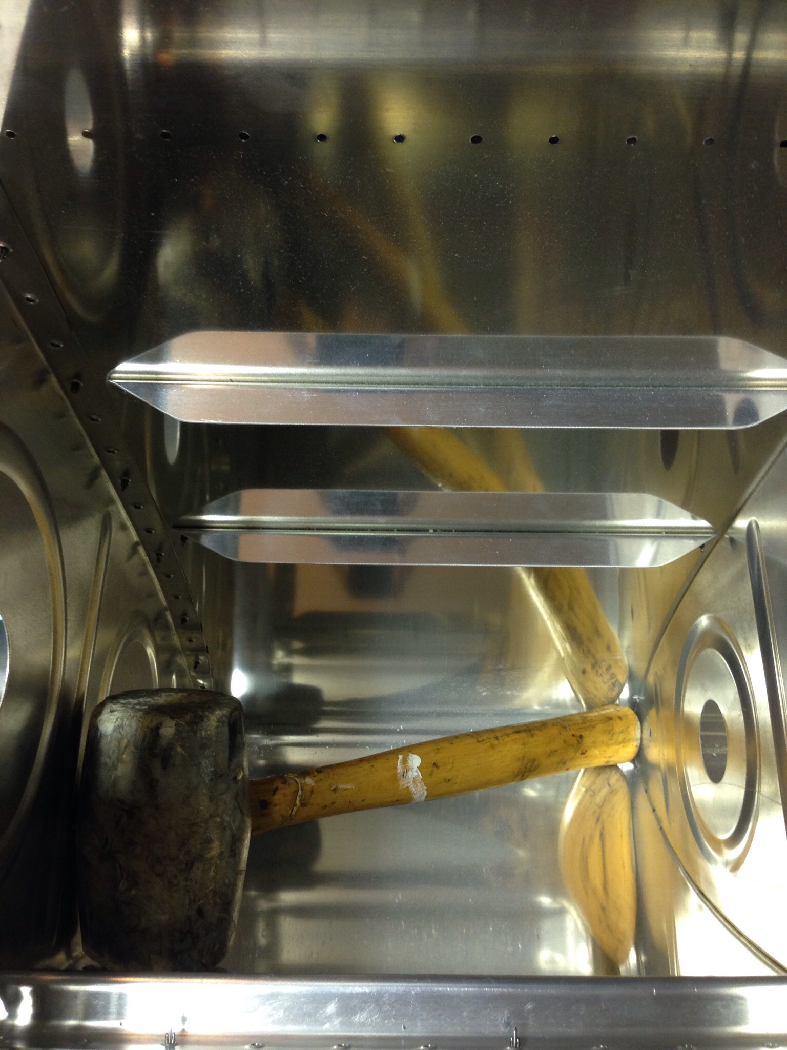
One piece of advice to heed, make sure nothing is in the tanks that doesn’t belong!  I had used my rubber mallet to tap some pieces into alignment.  I found it after enclosing the tank with clecos to match drill.  I looked all over the garage for that thing!

IMG_0324.JPG

Just a little trim

With the rudder complete according to the plans, it’s time for me to venture off into experimental land for the first time in the build.  A lot of other 10 builders are putting an electric rudder trim in and I want to do the same thing.  There are some great write ups on other’s build sites that I borrowed most of the ideas from and then just tweaked to make my own.

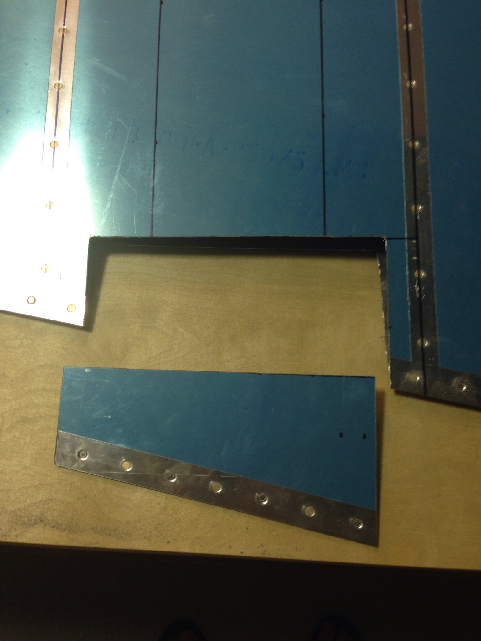
I started by laying out where the trim tab will be on the rudder.  I didn’t want to add any structure outside of the rudder, so I’ll be cutting a tab out and hinging it.  I choose the vertical mid point between two ribs for the location.  I then measured out the tab based on very scientific eyeballing and comparing to others.  I made sure to keep it centered and spaced evenly between the ribs and also to keep the hinge line perpendicular to the air flow.  Once copied to the other skin, it’s time to break out the Dremel and start stressing about making the cuts right.  It wasn’t nearly as bad as I thought it would be.

IMG_0149.JPG

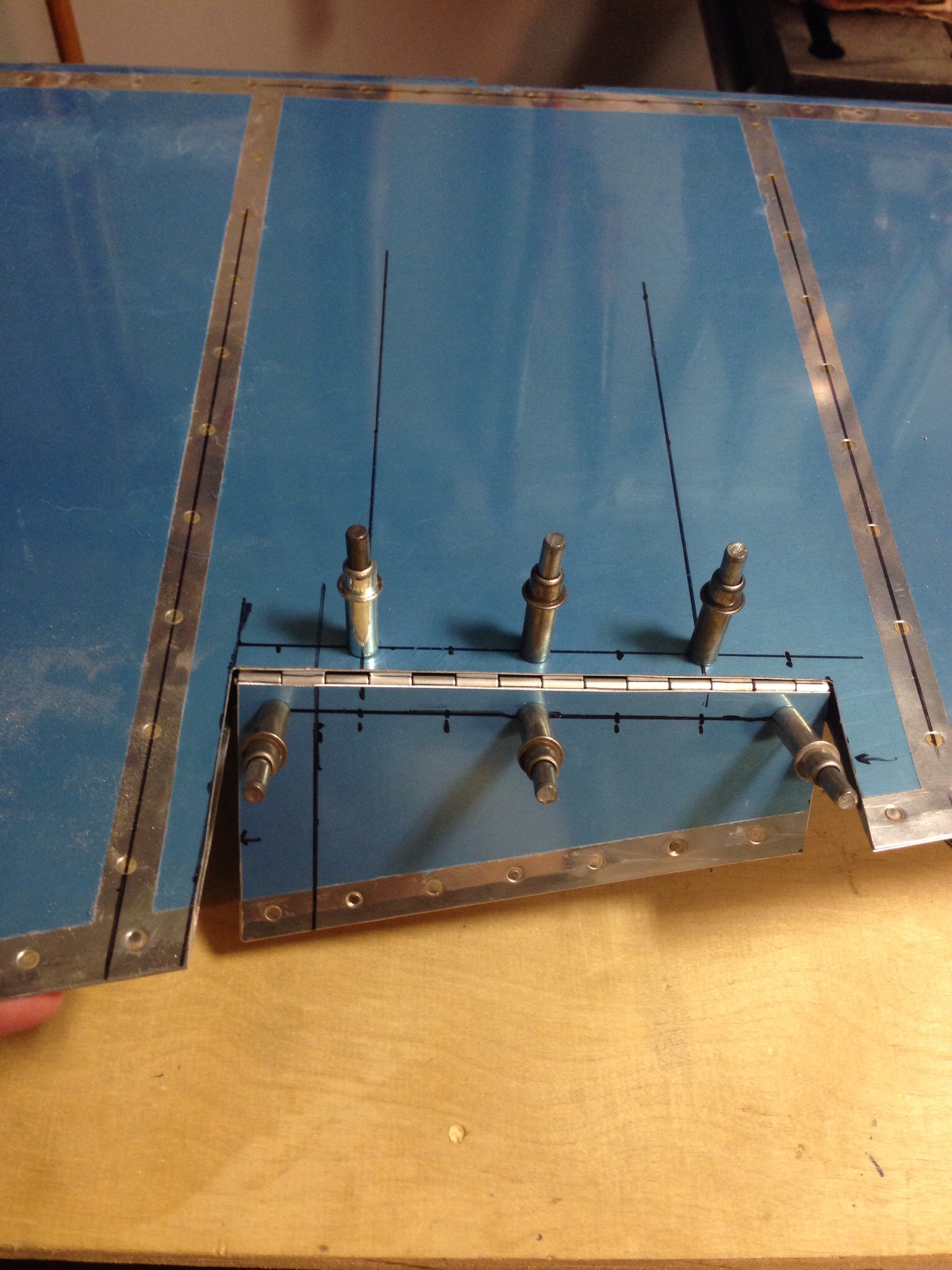
The hinge was next coming from a stick of piano hinge from Aircraft Spruce cut to size.  A main goal is to make it as drag resistant as possible, so I put the hing on the left inner skin which allows more movement to the right and a minimal gap when it is trimmed to the right (which is where it will spend most of its life).

IMG_0152.JPG

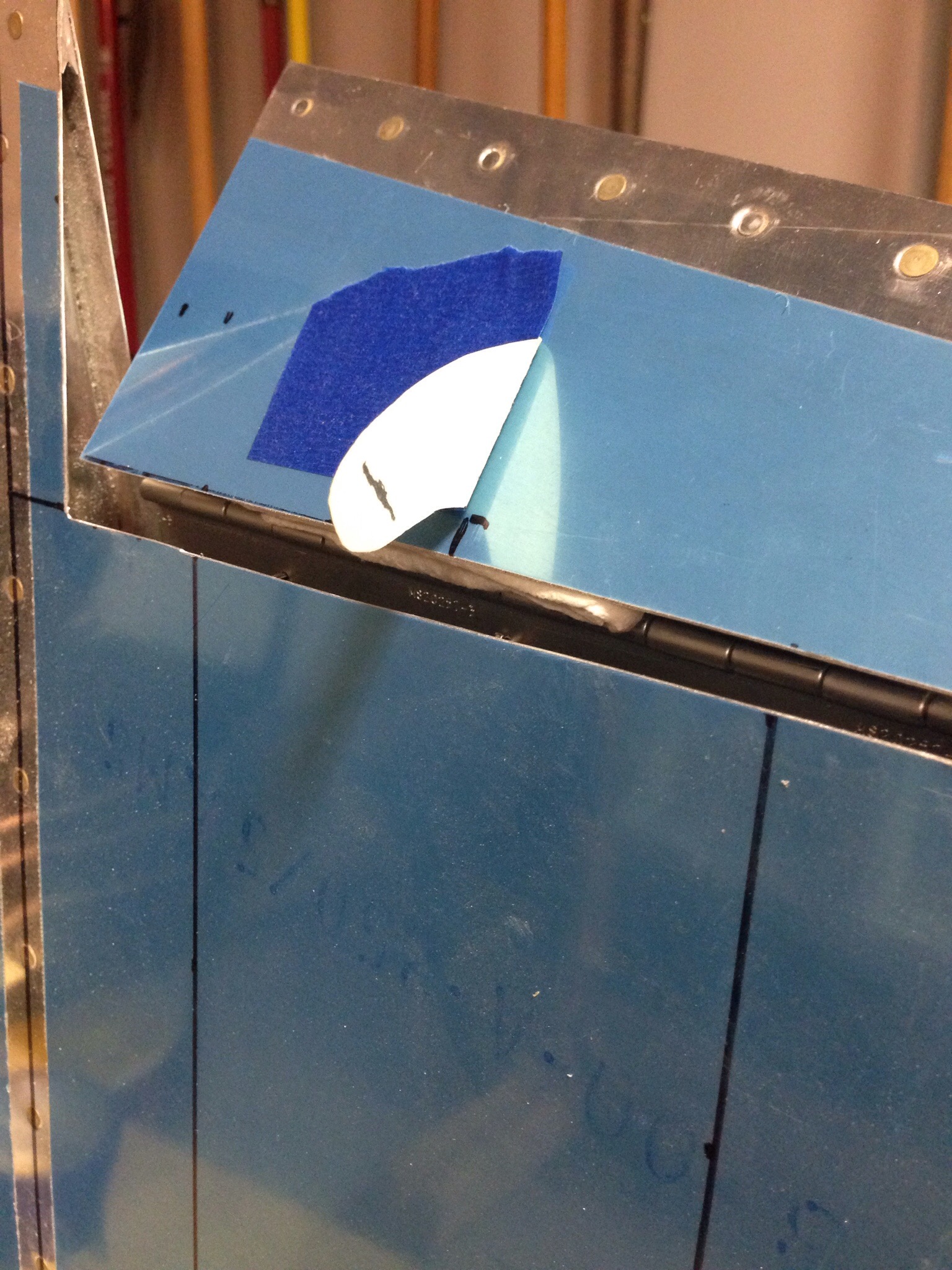
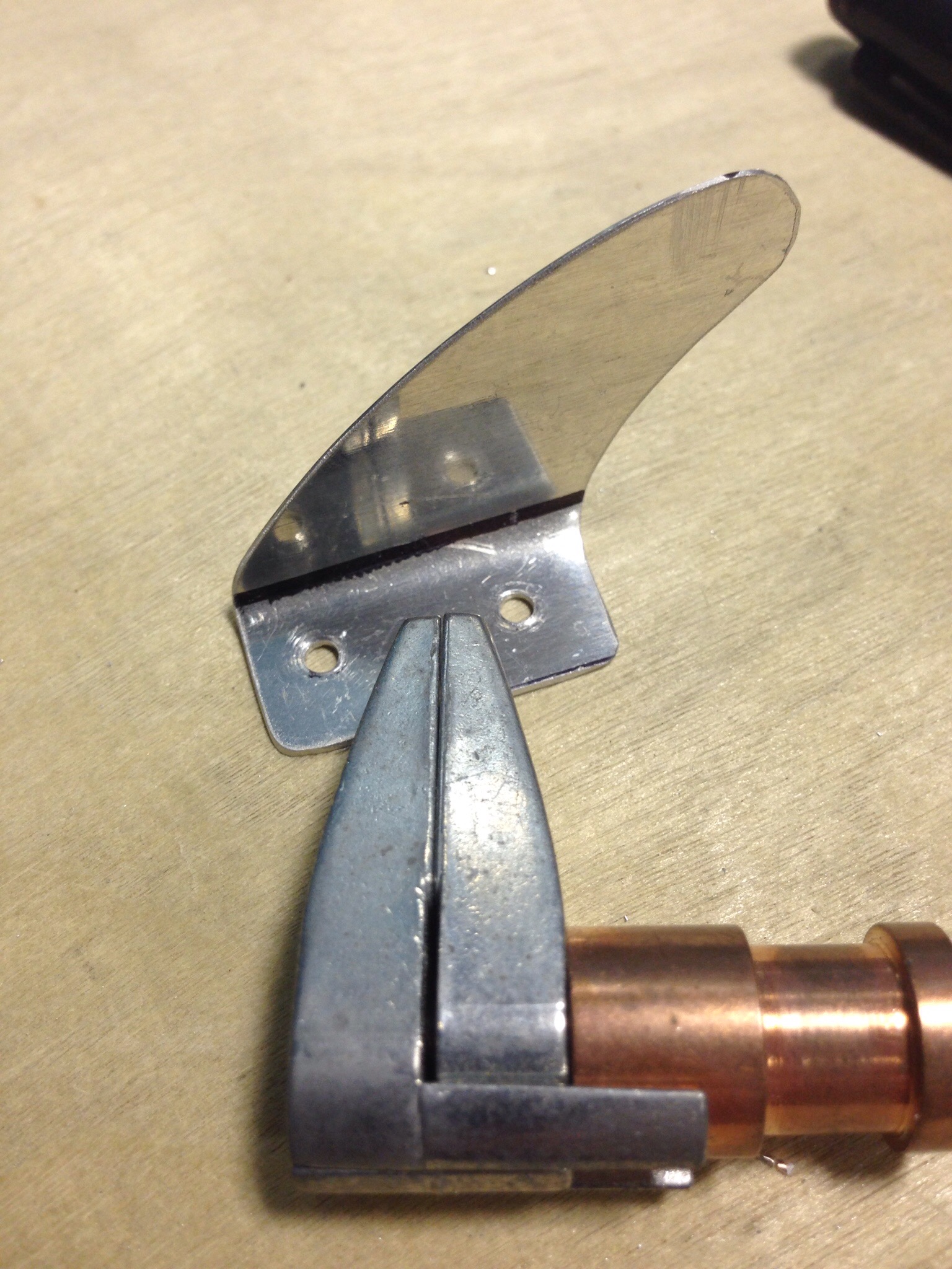
Next step was to create a mounting arm for the servo rod.  I started with a piece of manila folder to get the shape close.  This is where all my experience with RC models really paid off, as the system is very similar to any RC plane or helicopter set up.  I then cut two pieces of aluminum trim to the curved shape and bent the tabs in opposite directions to mount onto the trim tab.  Again, to minimize drag and maximize coolness factors, I cut a slit for the servo arm to slide through so I could have the mounting tabs inside of the tab.

IMG_0154.JPGIMG_0156.JPG

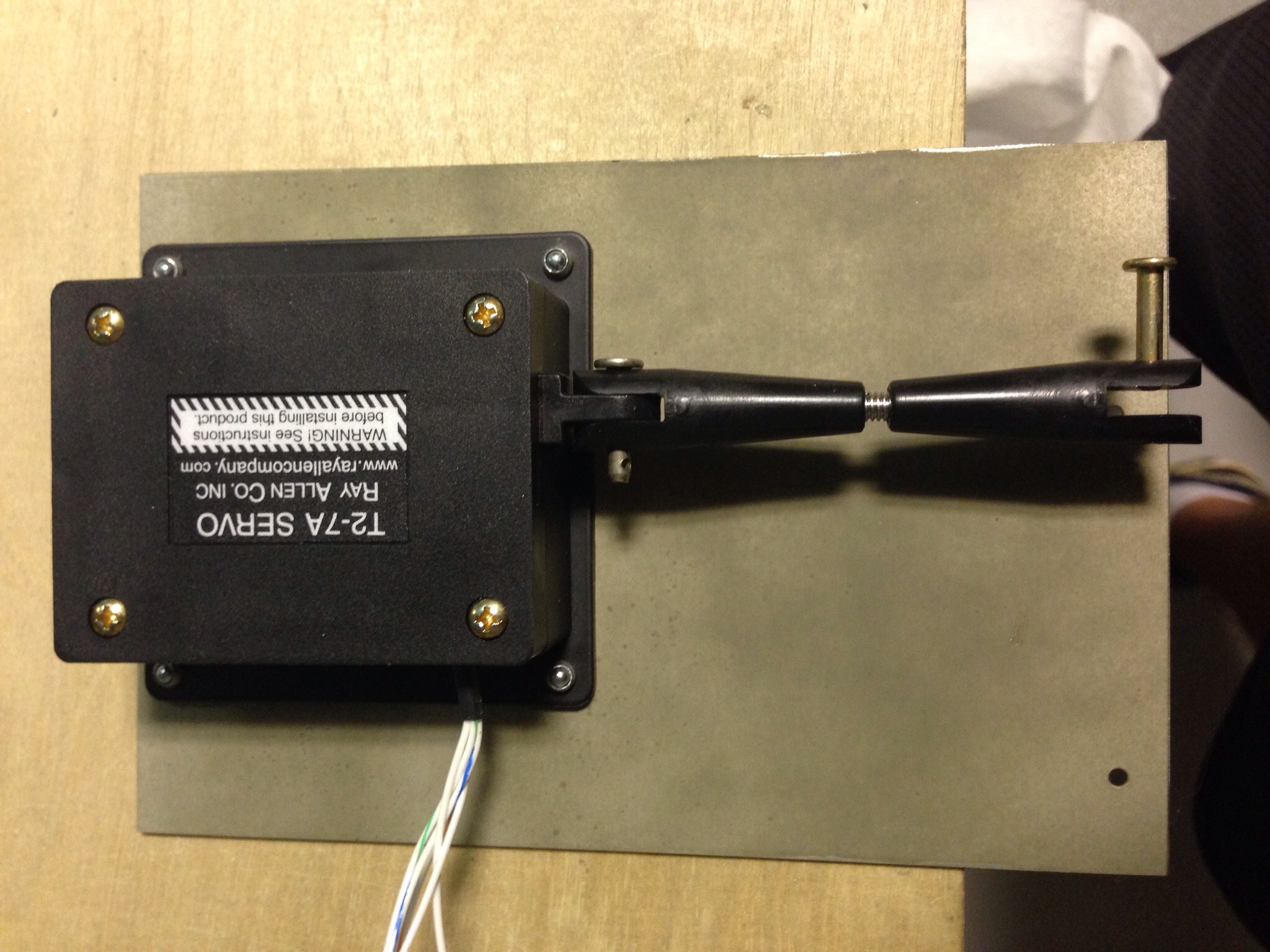
Rather than have an inspection panel with the servo mounted to it, I used another idea of having a piece of aluminum trim mounted to the hinge which serves as a base for the servo.  This way, I can remove the entire trim tab system, servo and all, from the rudder for maintenance using a minimum number of screws.  It’s also a little cleaner looking in my opinion.

IMG_0157.JPG

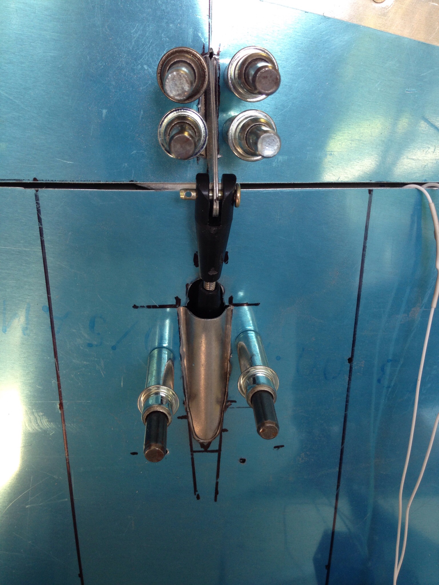
A rudder cable fairing finishes it off, again mounted from the inside and finished with a little micro and epoxy to smooth things out and cover the rivets.

IMG_0161.JPG

I trimmed a couple pieces of left over Styrofoam from the elevator trim tabs to epoxy in and keep the shape / provide structure for the tab.  I finished it off with a little micro to seal it all up.  The leading edge (non-hinged) was bent inward to create clearance for travel.

IMG_0165.JPG

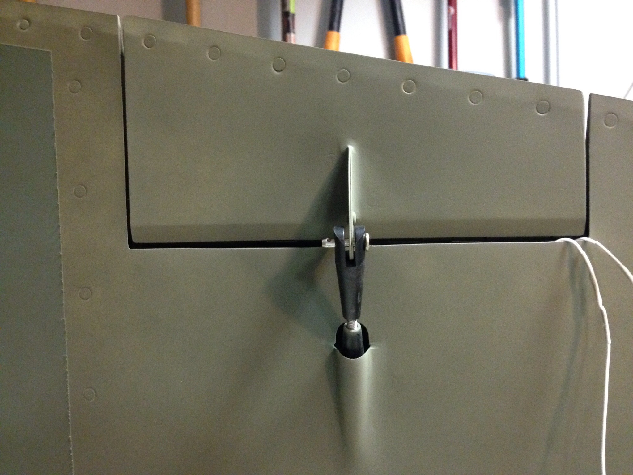
Overall, I’m very happy with the end result and it was a pretty easy project once all thought out.  I’ll hook up the wiring connector later in the build.  I did test it and get a pretty fair amount of travel.  Based on other’s I saw at Oshkosh, this will be more than enough trim power for the 10 even during full power climbs.

IMG_0168.JPG