We’ll just prop it up a bit

I’m always on the lookout for a good deal on anything that I can use for the project.  I’ll confess this is the best deal that I have or probably will ever come across.  VAF has proven to be a great resource for deals like this.  I happened to see an ad for a Whirlwind Aviation propeller.  I thought it would be too good to be true, but was surprised when I saw a 375RV prop for sale.  Brand new, still in the crate from WW, and listed a good amount below retail.  I immediately reached out to Chris, who had it for sale after buying a RV-8 project and needing a two blade prop.  He proved to be a great guy to work with and we quickly came to a agreement on price and shipping.  I was able to save a significant amount of money that will pay for over half of the interior.

I also spoke with Tanya at WW quite a bit, to make sure warranty will transfer, storage, and a few other questions.  She was fantastic to work with and extremely helpful.  If the long term support from WW is anywhere near my experience thus far, I’m confident I’ll never have an issue with them.  She even set me up with her shipping company and I was able to ship it from CA to NC for a fraction of what it would have cost walking up to FedEx or UPS Freight.
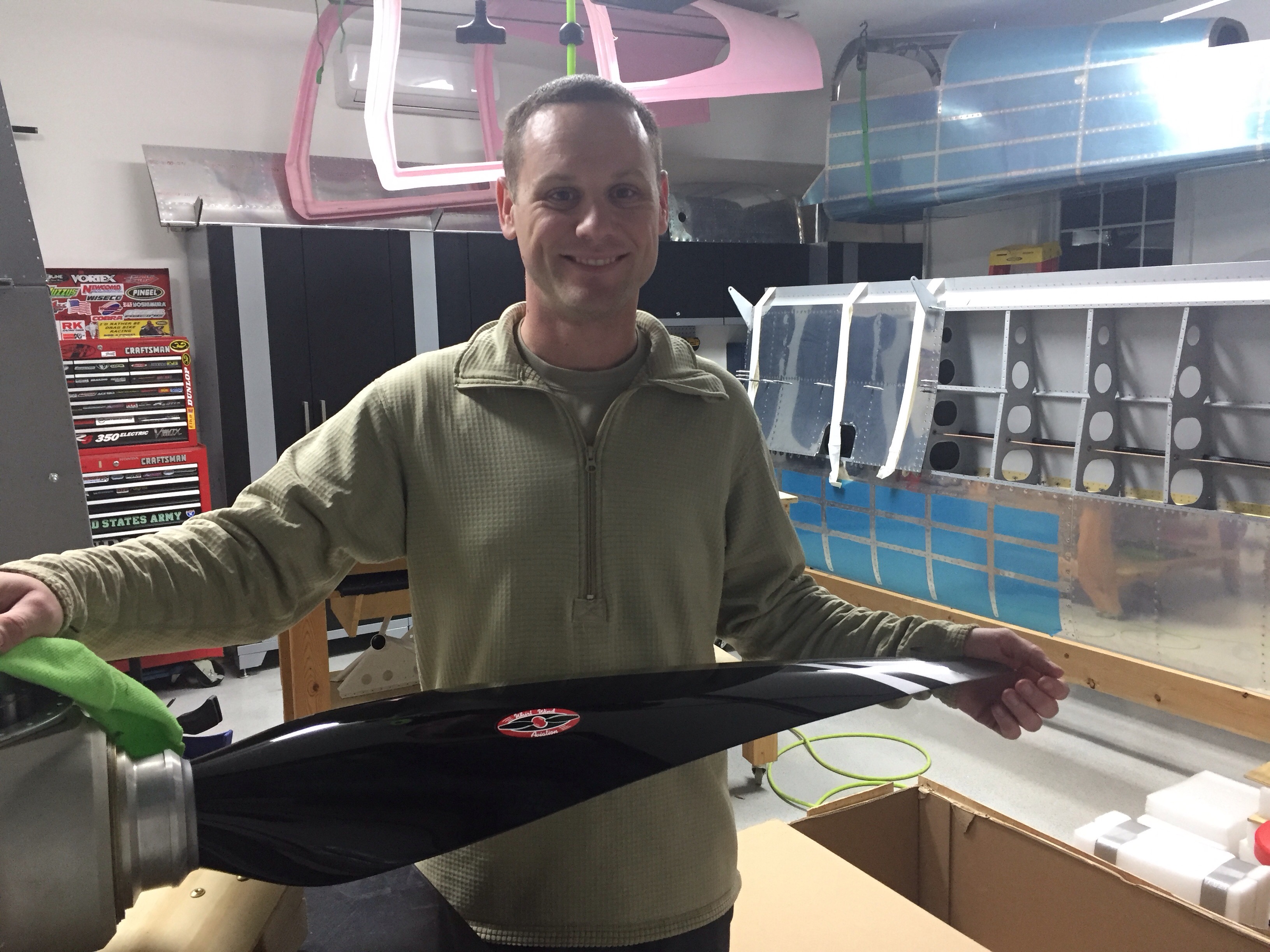
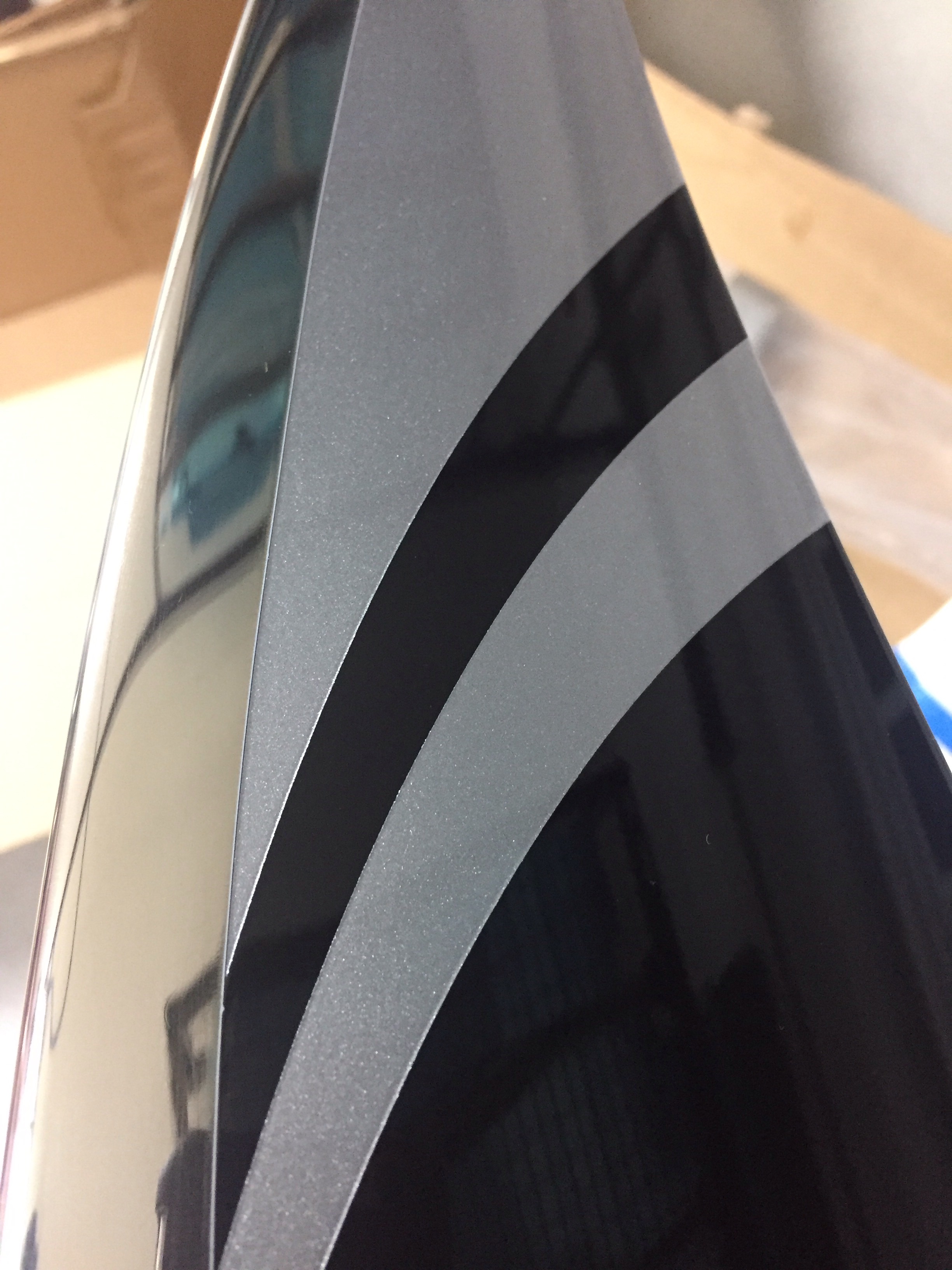
Needless to say, I was excited about opening it up and checking out my new purchase.  I also wanted to ensure there was no concealed damage.  Fortunately, Chris had reinforced the crate and all was well.  It is supposed to be stored vertically, and after finding out my storage plan of the common hangar at Lincolnton wouldn’t be covered under my insurance, I was left no choice but to mount it, temporarily of course, on the garage wall!
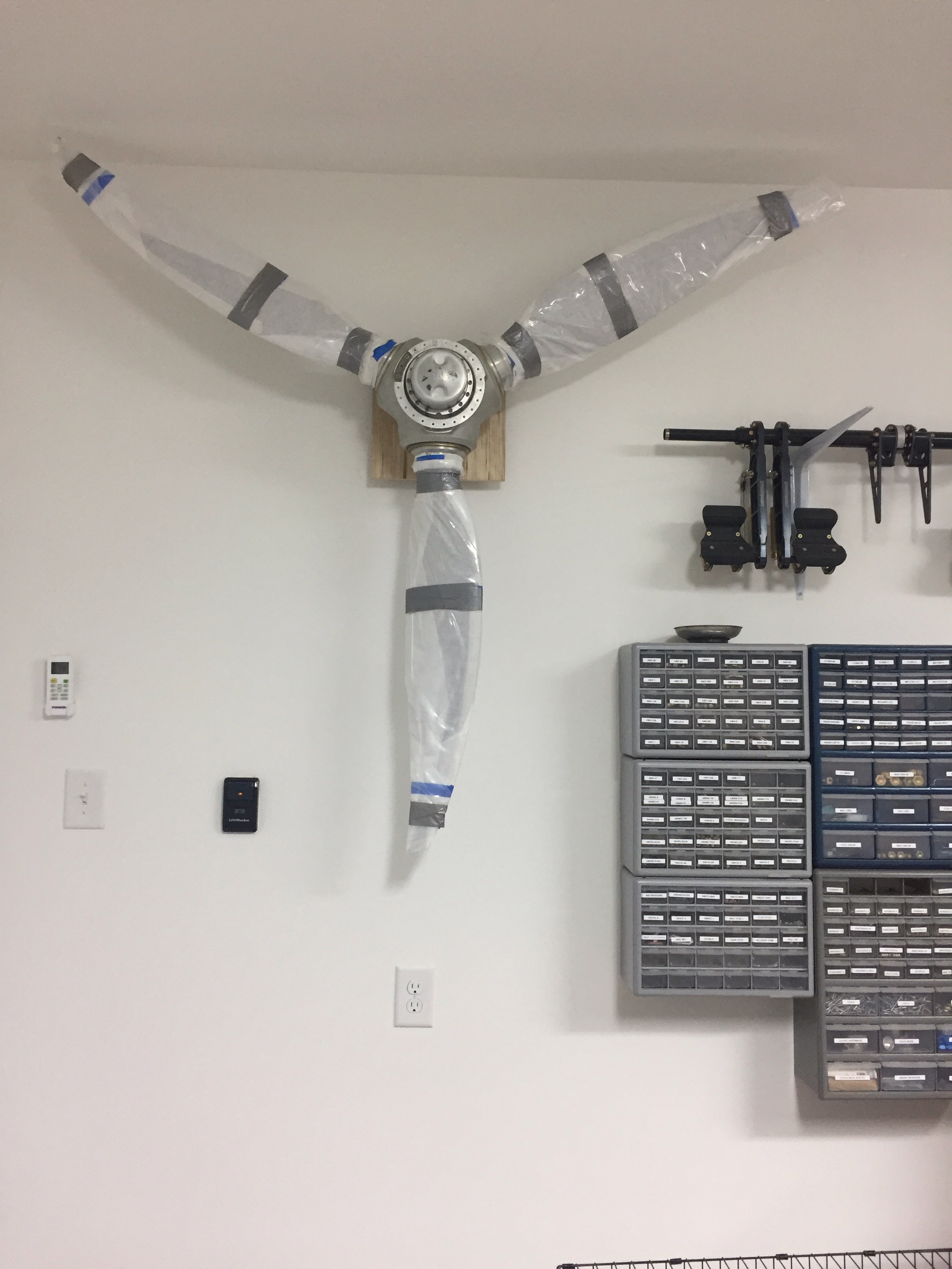

I have to say it worked out even better than I thought.  Out of the way and protected.  Plus, it just looks cool!  The prop itself is stmply stunning.  Almost too pretty to actually use.  It is a full gloss black on the front with silver tips that will match the paint scheme perfectly.  The nickel leading edge looks great and the sitar shape is producing good numbers from others who are now flying it.

On a side note, I spoke to a gentleman who was one of the first to fly behind the three bladed prop a few weeks ago.  He was great to talk with and provided a lot of great info and advice about the prop and RV-10 overall.  Sadly, he lost his life when his airplane crashed after a door was lost in flight.  I can guess what happened and what could have been done, but hindsight is 20/20 and the best thing anyone can do is try to learn from the tragedy.  It is a sombering reminder that flying is not without its risks and drives home the importance of building a mechanically sound aircraft that is operated in a safe manner.

Plinko Anyone?

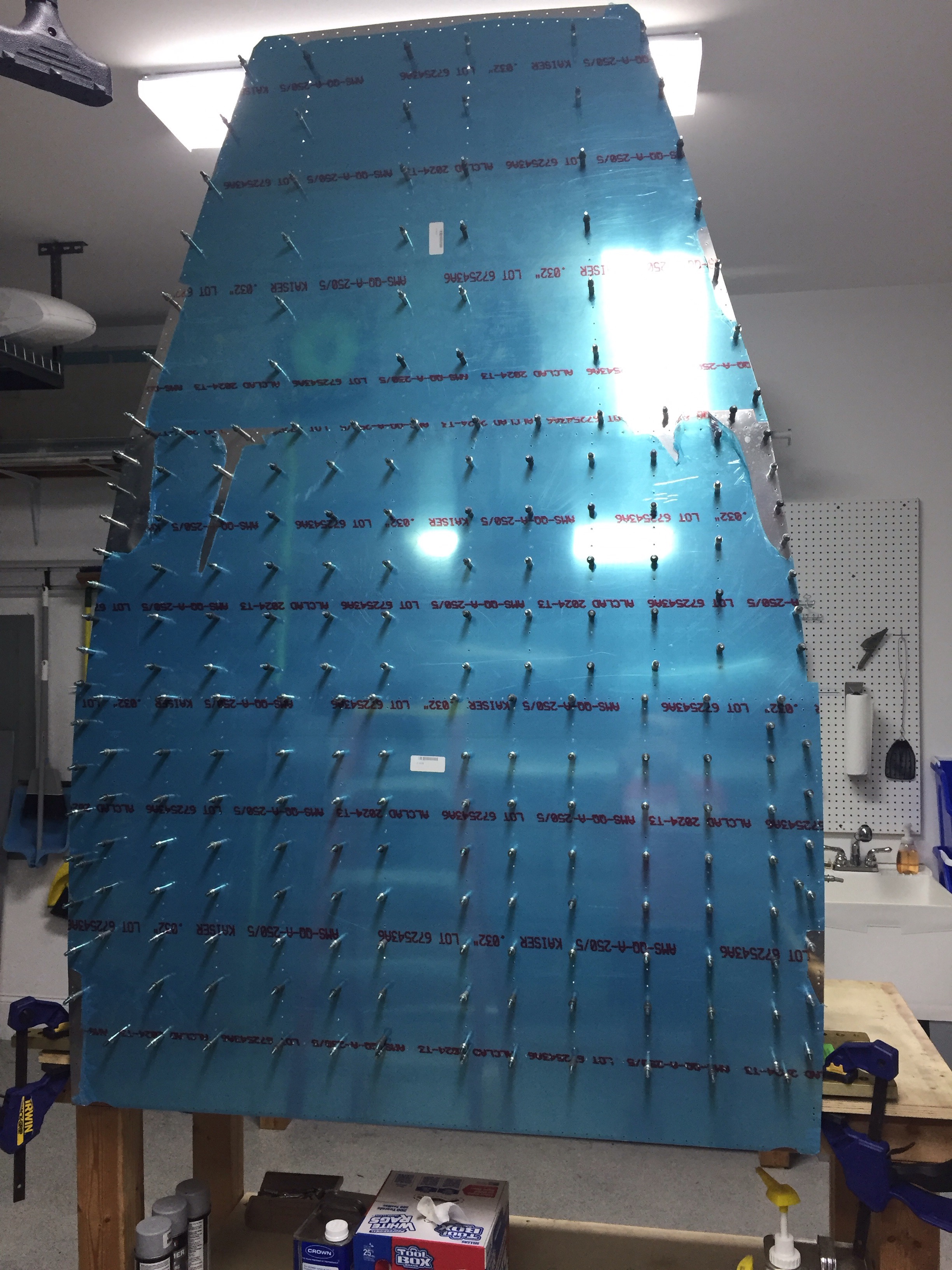
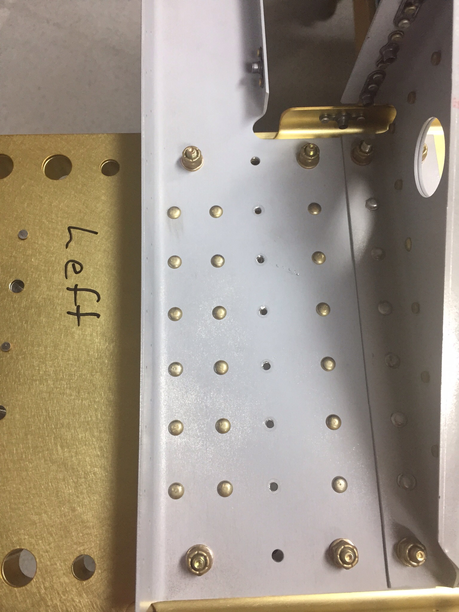
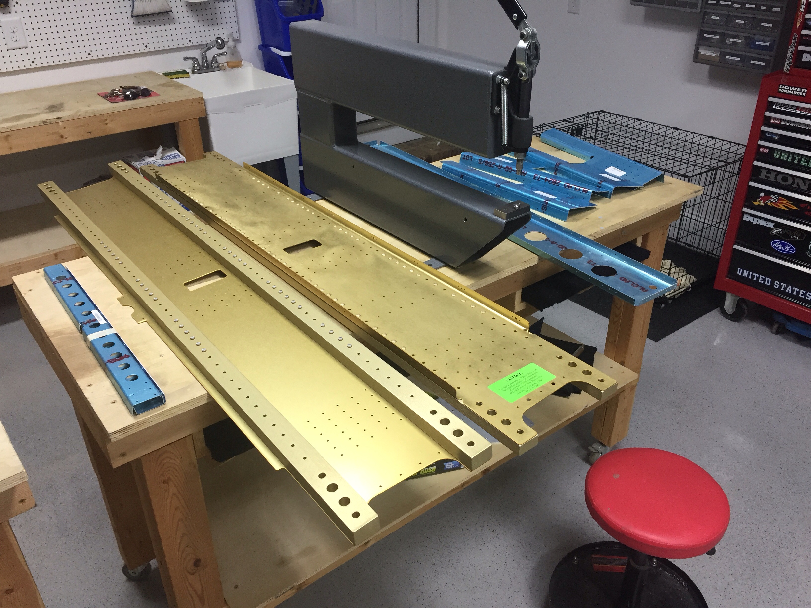
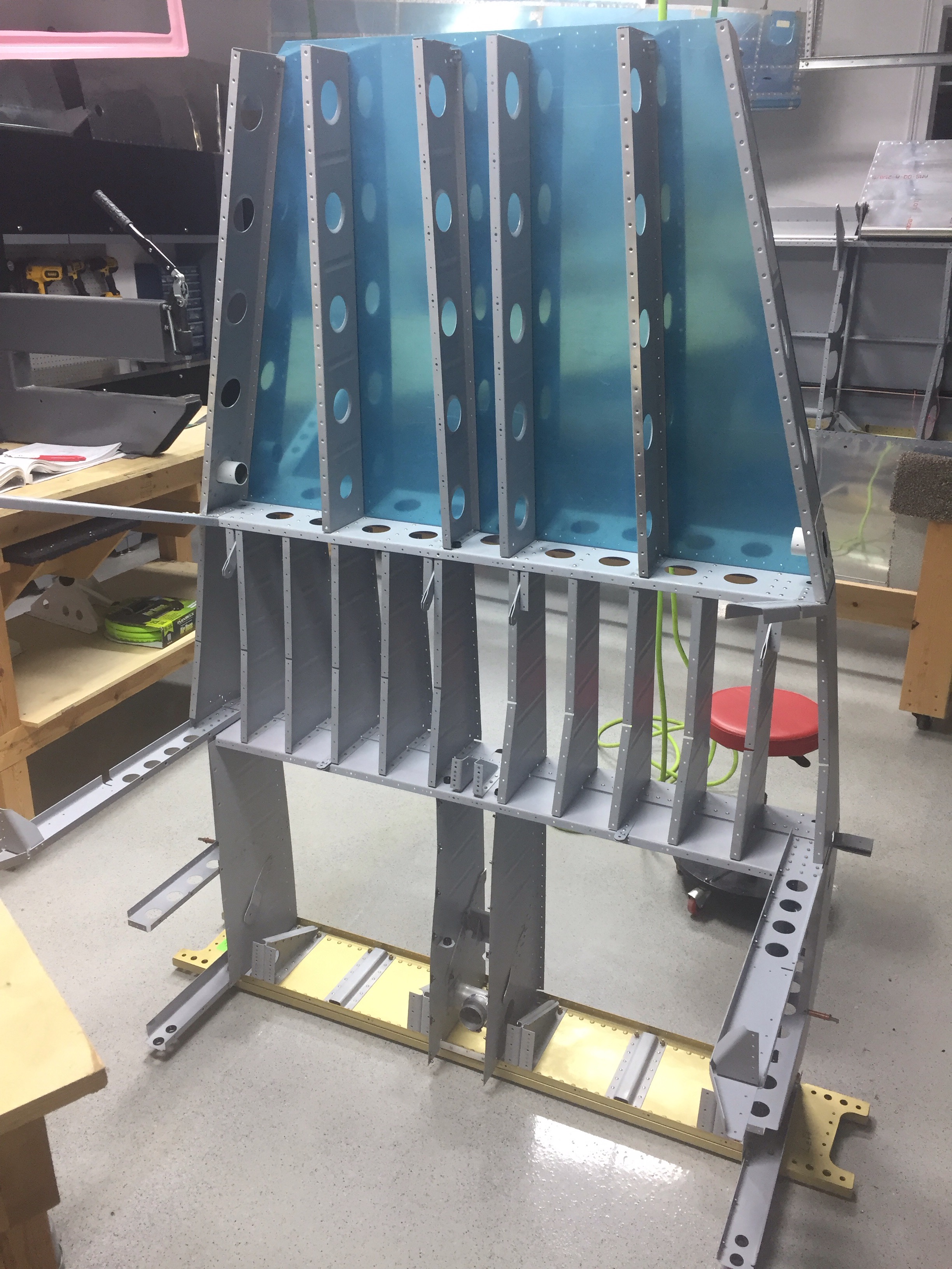
The bottom of the fuselage has a lot so structure to it, as it supports the wing spar and cabin payload.  The bottom skin reminded me of Plinko, just without prizes at the bottom.  It’s really just more of the usual for construction with this bottom skin.


In other news, I had my local EAA chapter technical counselor stop by and give the wings a last look before closing them up.  I got a great report card on my work and another report for my final inspection.  While it’s not a blank check, I have heard quite a few folks say the final inspection is a bit easier when the FAA see a history of routine inspections.  It’s nice to have your work validated as a quality product as well.  It’s good motivation to keep charging on the project.

I’m craving ribs

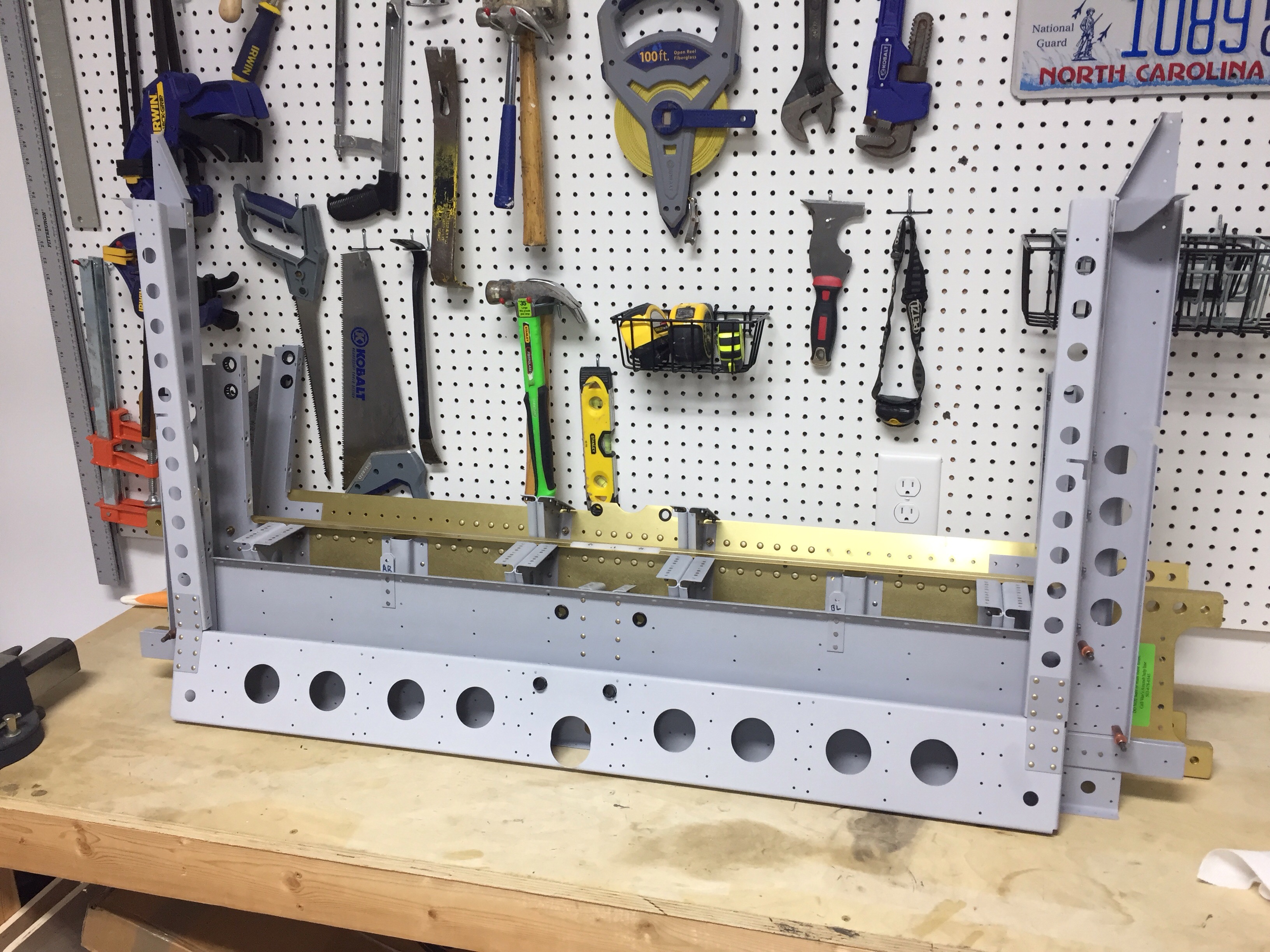
Once the bulkheads are all together, there is an infinite amount of ribs that are attached making up the bottom of the fuselage.  It’s also where the pilot and passengers park their butts, so it’s pretty important to get right.  Fortunately, I’m really good at drilling out rivets.  More on that in a minute.


The ribs take a lot of work to prep, as they are very closely spaced and there’s a lot to scuff and prime.  The prepping alone took a few hours and got a bit boring.  It was also a bit tricky making sure I had everything in the right spot.  Attention to detail on the plans was important and I had to reference a few future sections to see what the bigger picture is on where stuff goes.


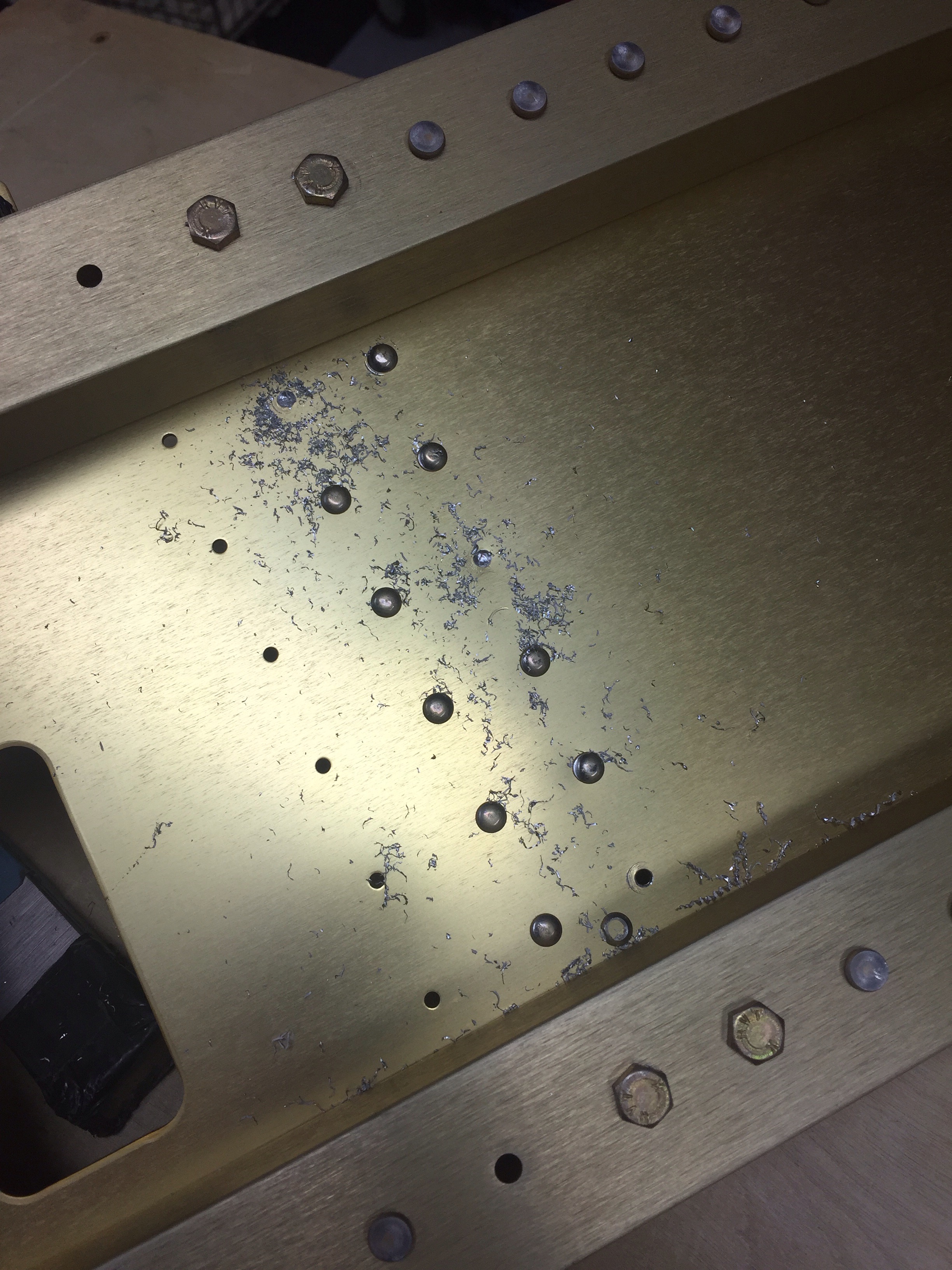
Finally everything is primed and now it’s time to rivet.  I just can’t get into a groove with my offset rivet set.  I am drilling out about a fifth of the rivets because I am smashing the manufactured head.  I also riveted an outside rib on without putting the other end of it inside a bulkhead, so all of those rivets had to come out.  I had to slow myself down and refocus which is yielding better results.

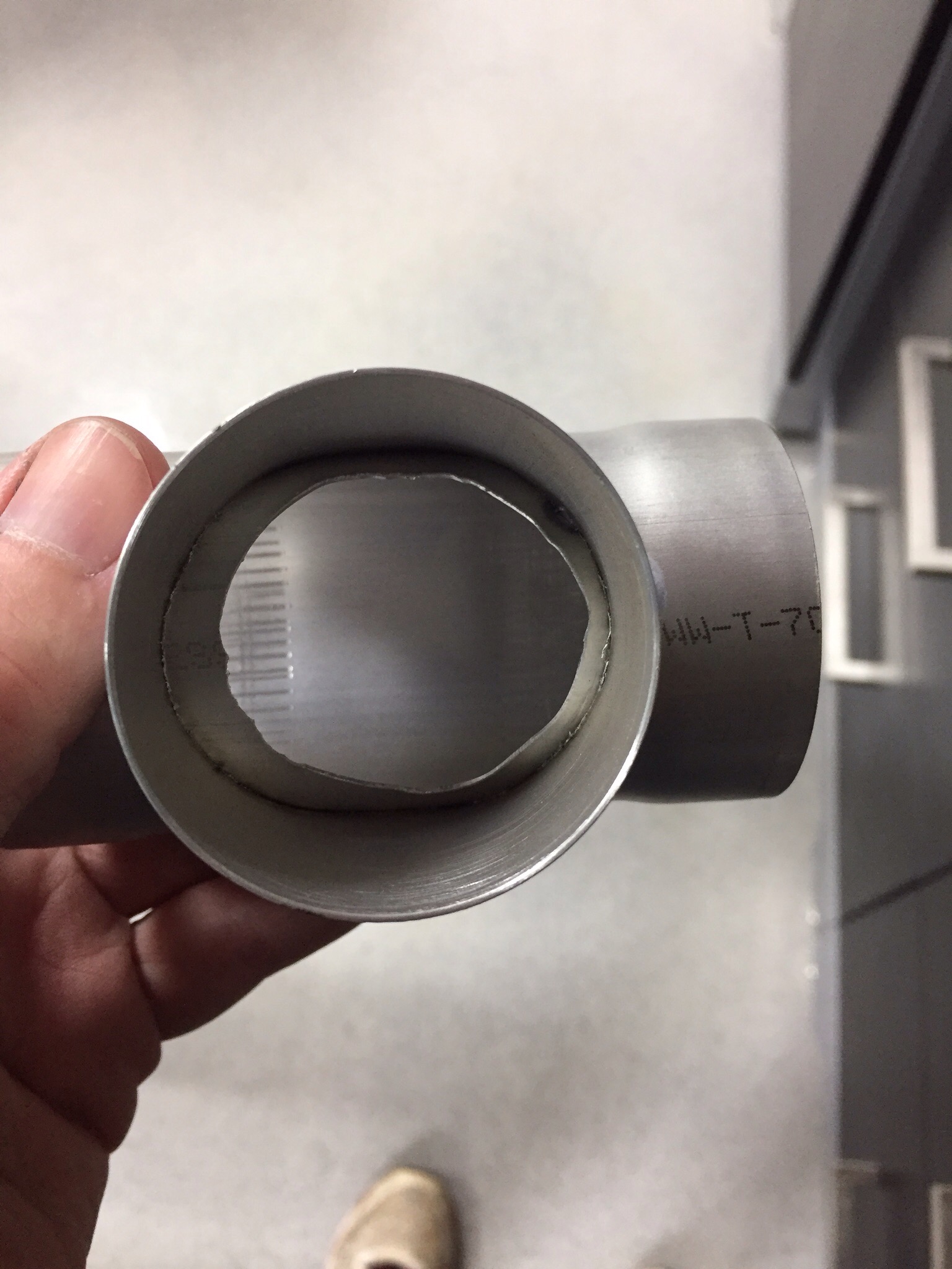
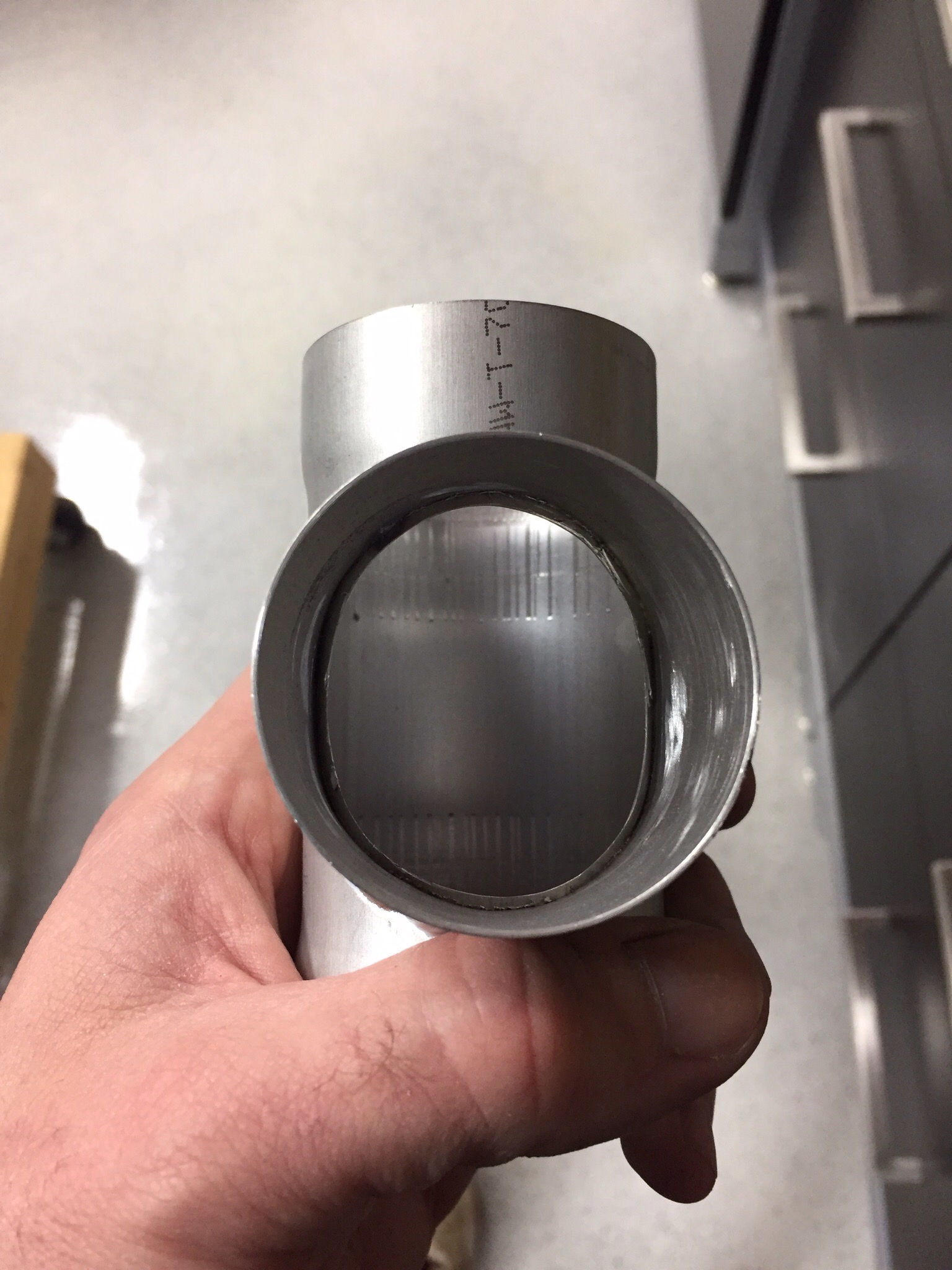
I did take some time to clean up the heat duct tee before installing.  I’m sure there is plenty of heat in the back, but why leave an ugly piece in the project when I could fix it up.  Before and after shows a nice increase in the outlet area so it should provide smoother airflow compared to the original condition.

Well, buck it

Sometimes you’re on and sometimes you can’t figure out why nothing you touch works or ends up as it should.  Tonight I attacked riveting the aft spar and seat rails.  I had bolted and torqued everything the previous evening as I was tired, and it took long enough with the large quantity of bolts on this spar.  On the forward spar, I used the DRDT2 with rivet dies to squeeze  most of the rivets, but had to buck all on the aft spar.  There are a lot of rivets that you have to get to with the offset head and it took quite a few terrible rivets for me to get in the grove again with all of my tools.


I also was mentally worn out from work and despite consulting the plans many times and noting one line of holes should be left un-riveted, I filled them with beautifully set rivets on the left side of the spar.  So I had to drill all of those out before moving on.


Now one would think you’d remember that on the right side, but not me.  Filled that line up with perfect examples of bucking rivets.  Awesome.  Drilled those out.  I also took some time to really closely inspect all of the other rivets and drilled quite a few out, as I wasn’t happy with them.  Taking my time and a deep breath, the second attempt on each one of those turned out vastly better than the first.  It’s one of those cases that I’m sure it’d be fine and the airplane would never notice a few imperfect rivets, but I haven’t taken a “that’s good enough” mentality yet and don’t want to start now.

Time to start fusing

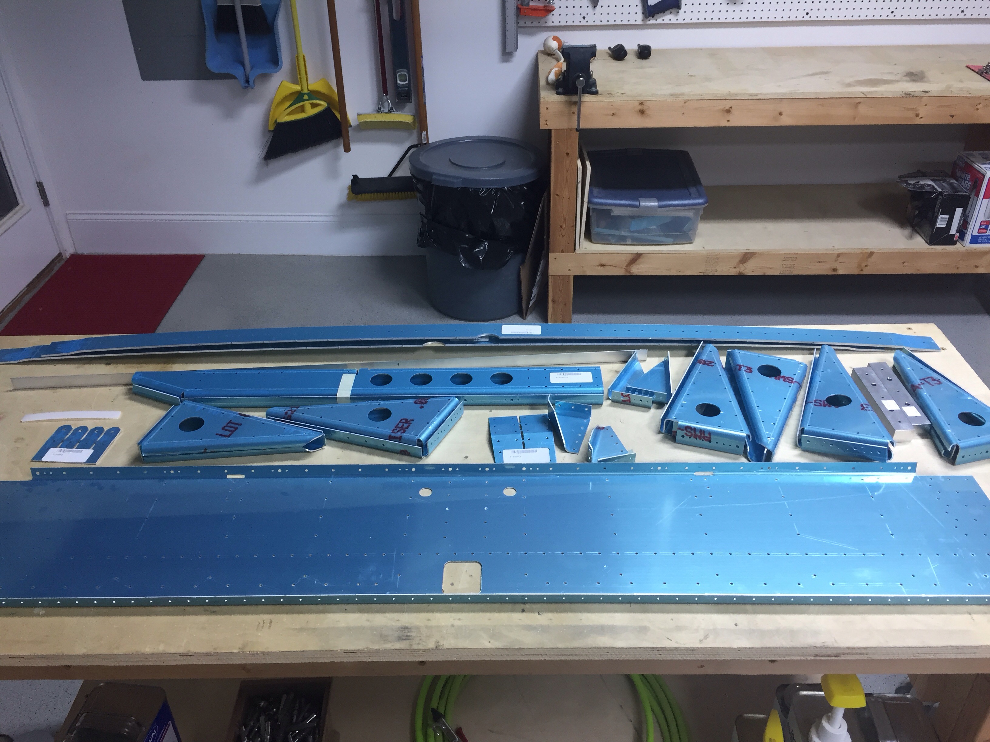
With the decision to hold off on the bottom wing skins until after another EAA tech counselor visit, it’s time to move onto the fuselage kit.  This kit arrived to our old house over a year ago, and has since been stored on the overhead racks in the garage.  The first challenge was to find all the associated parts that resulted in lots of trips up and down the ladder.  Alas, I finally located everything and was able to get started on the spars and seat rails.


I’m already seeing a lot of smaller pieces but many more than in the wings, and of course beefier substructure as it carries most of the loads of the aircraft.  After the normal routine, I got to riveting and quickly remembered it’s been a year and a half since I’ve bucked a rivet.  It has also been a year and a half since I’ve drilled out a rivet.  I can now say I’m current on both tasks.   


The front spar is all ready to go with the aft spar and assemblies up next.  I’m also happy to say that for the past three weeks, I’ve worked on the airplane every single day, whether it’s physically in the shop or electrical planning.  Not only am I really feeling motivated by that, but I’m also making a lot of progress.

Excuse me Sir, but your pitot is showing

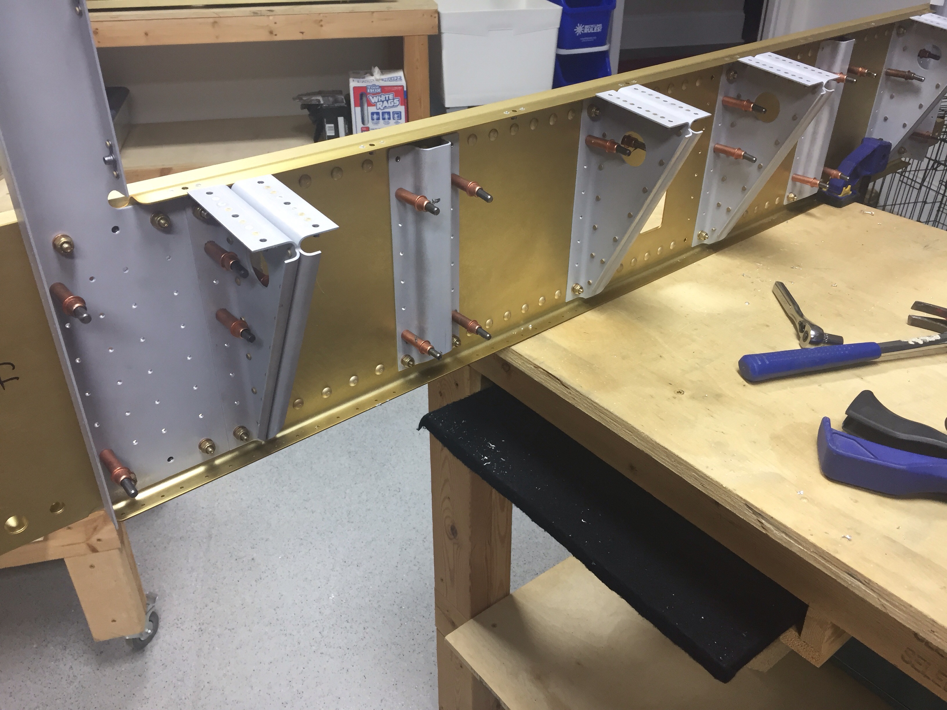
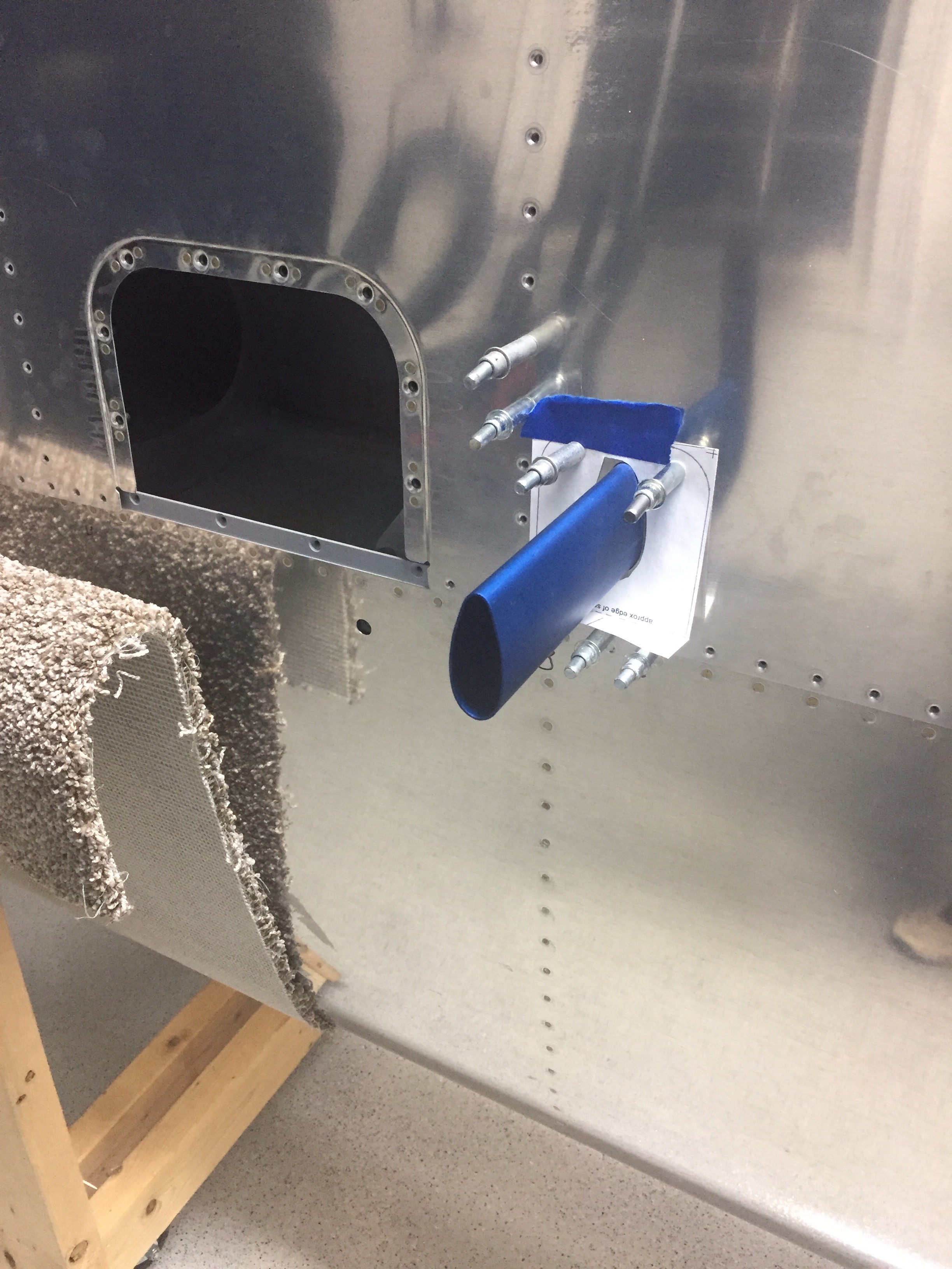
Turns out, the pitot is much easier to install before putting the bottom skins on.  I learned this thanks to the great info from other builders’ blogs.  Check out the link Other Build Logs for some of my go to’s.  It’s good advice, as it gave me a lot of room to mount the heater controller and the actual mount itself.

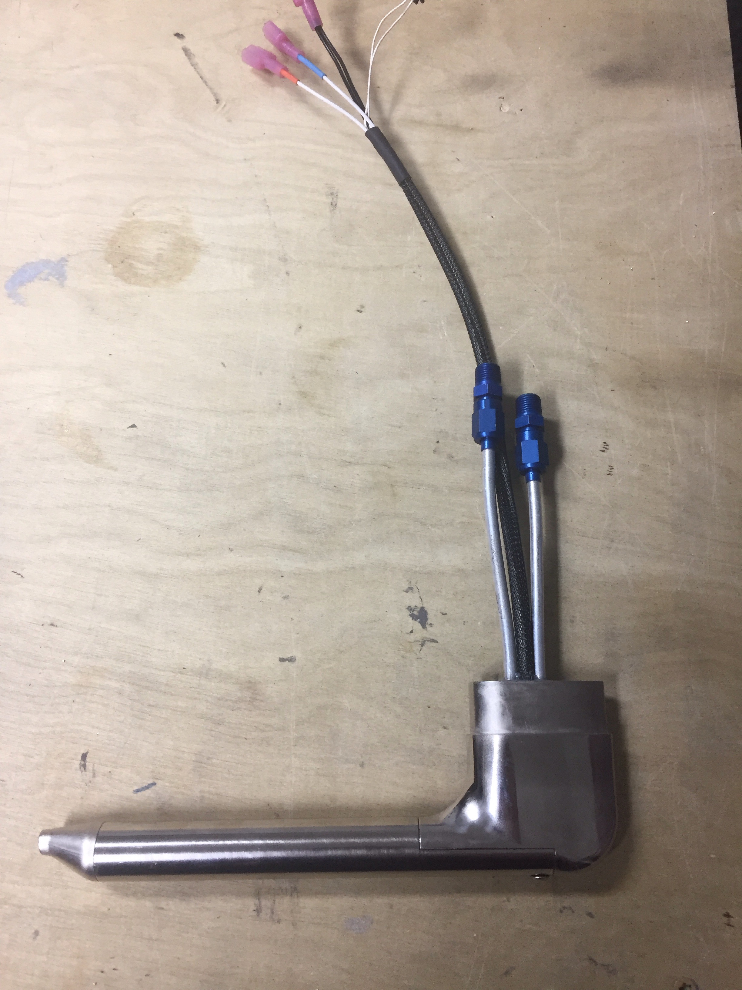
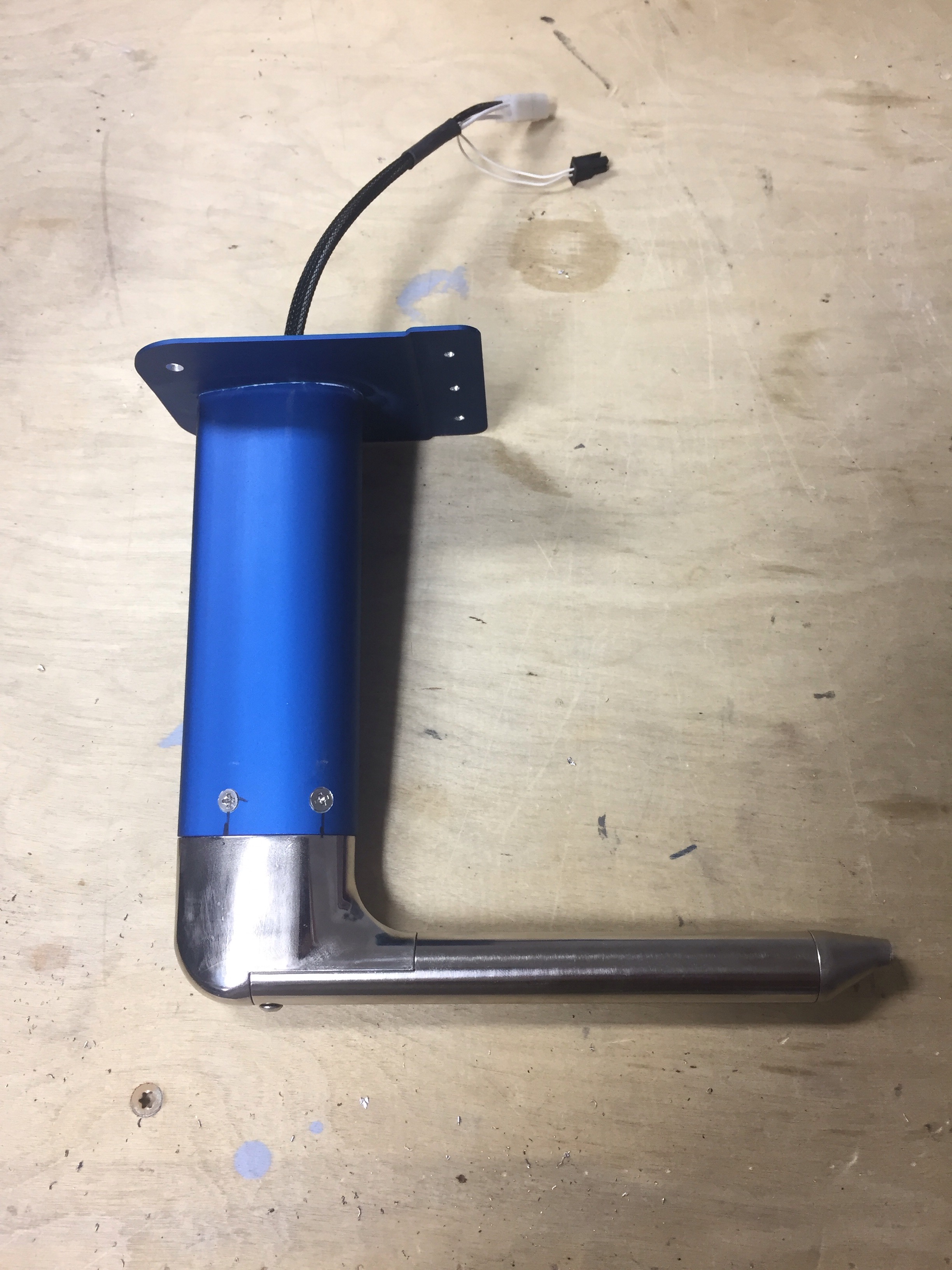
I’m putting in the Dynon heated AOA and pitot tube along with the Safe Air mount.  Great products all around and the process wasn’t too bad.  First step is marking and cutting the hole in the skin.  Safe Air provides a nice template for this and a Dremel makes quick work of the task.  I chose to use the standard Van’s location just inboard of the tie down location.


I used a bottoming tap to carefully cut threads in the pitot tube, making sure the drill and tap stayed clear of the tubes.  I also installed the fittings which allowed me to use the new crows foot wrenches.  It did surprise me how much torque they require, as I was afraid of ruining them.  But they shouldn’t leak now that they are good and tight per the specs.


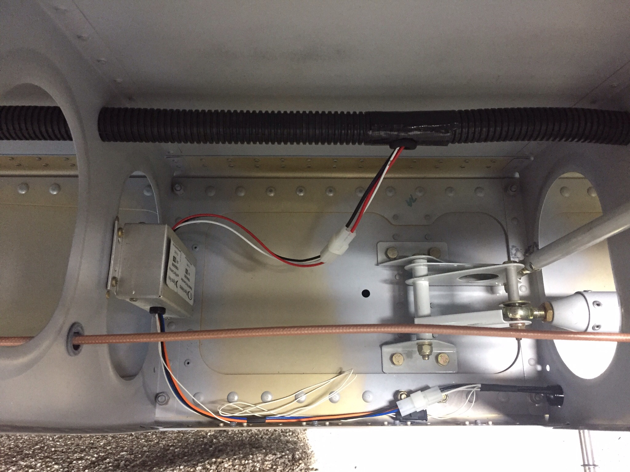
I also got to break out my Stein wiring kit for a connector and pins.  I’ve used a similar crimper before, so the hardest part was figuring out which pins went into which side of the connector.  I shortened the wires to reduce the amount of slack wiring inside the wing and put the pins on with ease.  The only thing left to clean up is putting some braided sleeve on the wires to provide some abrasion resistance and spruce them up a bit.


One piece of advice is to mark the wires coming from the pitot itself before cutting off the spade connectors.  There is a blue and orange connection from the controller but both wires from the pitot are white with a corresponding piece of heat shrink on them.  I had to email Dynon and get a trick to identify which wire went to blue / orange.  They advised a great trick to freeze the pitot and determine which is blue / orange by seeing which side of the tube heated up first.

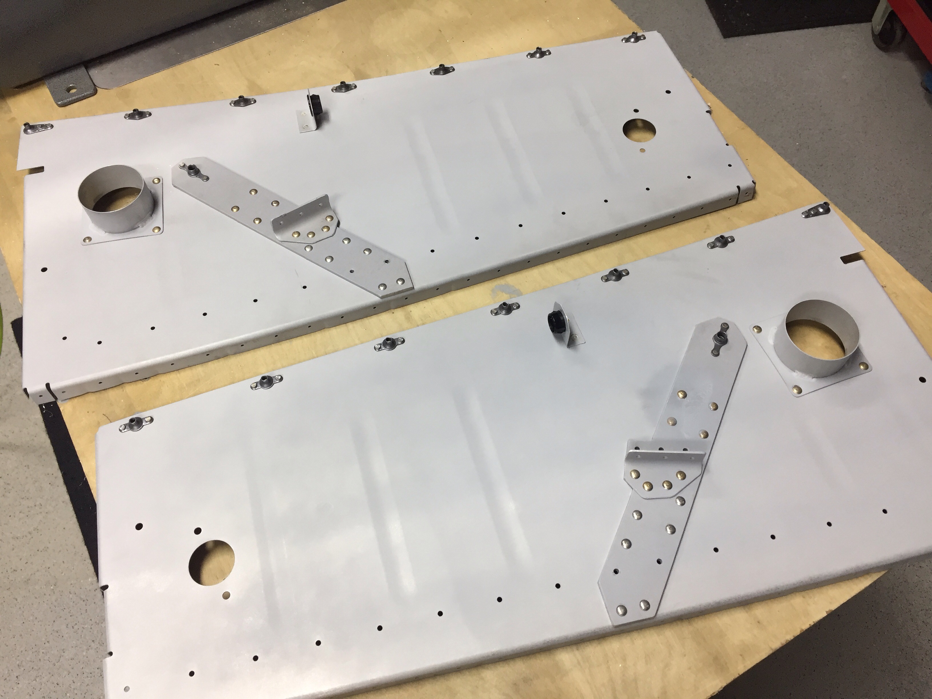
I originally mounted the controller to the access panel as others have done, but didn’t like that with having to tuck wires in so I decided to follow another builders idea of putting it on a rib.  Adding four nut plates makes it a clean instal and still allows easy to access once the bottom skin is on.  Overall, I’m very pleased with the install and looking forward to having the integrated AOA display in the cockpit.

Service Bulletins

While having some down time at home that I can’t do much productive anything with, I decided to research quite a few things while lying in bed after surgery.  One of those was service bulletins.  There are a handful out there for the RV-10 and are a lot like AD’s issued by the FAA, but they are not mandatory by law.  Highly recommended, however, so in the home built world, you comply with them.  With this being a build log, I wanted to document them here and then I’ll make the associated entries in the air frame log book once I have one.

The empenage kit (oldest original kit) was delivered in October 2005 to the original builder, thus I have only addressed those SB’s relating to the dates affecting our kits.

SB 06-2-3 is for the vertical stabilizer rudder mount.  This SB was completed by the original builder and complies with all aspects of the SB.  I could not get a good picture inside a tiny access hole, however, visually confirmed the doubler plate is in place inside the main spar of the VS.

SB 06-9-20 is for the trim cable anchor nut on the elevators.  While our kit does have the double welded nut, I chose to upgrade to the CNC machined piece by IFLYRV10.com.

SB 08-6-1 is for the F-1010 bulkhead near the vertical stabilizer in the tail cone.  My kit came with the SB contents and I completed it as part of the original build of the tail cone.

SB 16-03-28 is for the aileron hinge brackets possibly cracking on the inboard aileron mount.  I have removed the portion of the gap fairing to allow future inspection and no further action is needed until flying, at which time an annual inspection of the bracket must be made and noted in the log.

There are other SB’s that will affect our build, however, I have not gotten to that stage of the build yet, so will cover it in another post.

I’ll be right back under construction

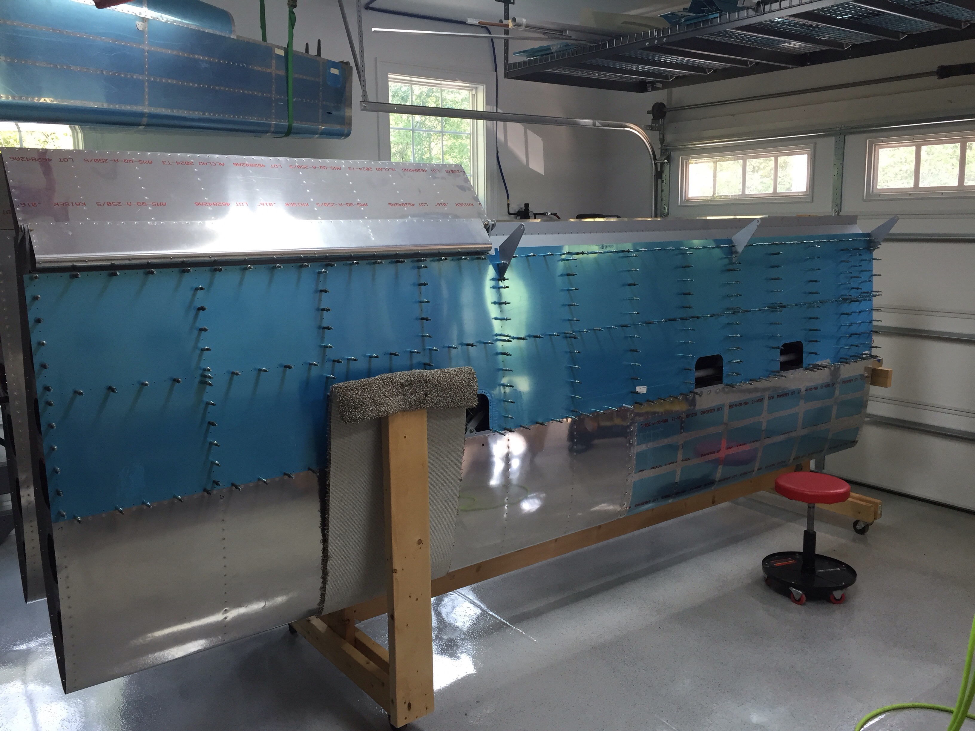
After almost a year and a half, construction on our RV-10 is back under way!  Now that the new shop is done and organized (check out the Garage Part Deux), I’m making time to get the build back on the top of the priority list.  With as much time away as I’ve had, I decided it’d be a good idea to review the plans and remember just where I had left off.  The last check mark was in the aileron rigging section, so that’s where I dove in.  I decided to go ahead and rig the control surfaces before riveting the bottom skin on just to have easier access and am glad I did.  If needed, I can always remove the large pushrod now that it’s all tweaked to have the surfaces lined up properly with the control arms.  I also added the spring attachment points for the aileron trim servo, having made the servo mount a while back.

Next up is buttoning up the wing bottoms.  I took a long last look at both before moving forward and read a lot of blogs to see if I could do anything else before losing easy acces.  I’m glad I did because I realized I had the trim servo wiring going to the wrong spar location.  That was a quick fix and I’m now confident I’m ready to put the bottom skins on.  The only item left to add is the pitot tube mount, but the bottom skin has to be attached first.


I did have to modify the rack yet again as the carpet post was too tall and blocking a few rivets.  A quick fix with the circular saw and reattaching the carpet.  Not a whole lot of exciting details, as it’s a lot of basic processes with a lot of repetition.  Good practice to get me back into the swing of aircraft construction, though; and I’m really enjoying being out in the shop working again.  Unfortunately, I’ll have to take another few weeks off for back surgery recovery, but at least I got a start on it again!

Mind the gap

So it may be noticed there was 440 days between posts with little progress made on the build in the past year.  Well, we decided to make a life decision and build a custom home after we realized we were at a point in our lives we could actually make it happen.  I won’t dive into the details on house building, as that’s a whole other blog topic, but it was an adventure to say the least.

IMG_0013(1)IMG_0010(1)IMG_0011(1)
Long story short, we now have a beautiful home custom built on 10 acres of heaven with lots of trees, hills, and a great creek.  Oh, and did I mention it’s a mile from the IPJ runway and on the base leg for the 23 approach?  Yes, I did say heaven!  My wife and I both grin watching the airplanes a few hundred feet above us.

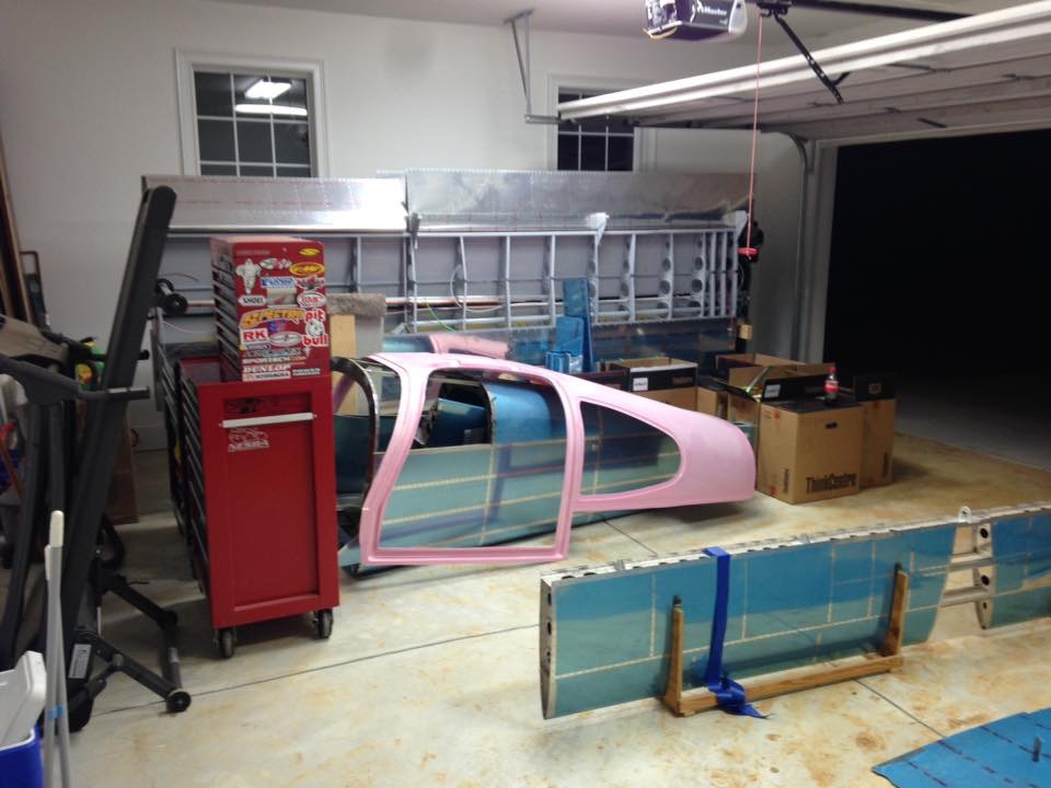
The project has been on hold and in storage throughout the house project, but I am happy to report it is in the new garage.  Unfortunately, I had to go TDY for the military 5 days after we moved in!  So the “shop” has a bit of work to be done when I get home.  Epoxy floors, nice cabinets, AC/heat pump, and parts storage is all on the list.  Then it will be back to building in earnest.

IMG_0014(1)


That moment in the middle of the night you wake up and realize…

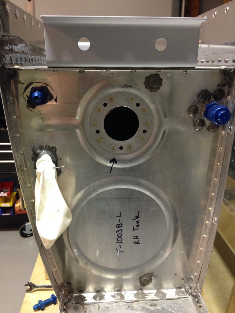
…that something off plans you did has already gone very wrong.  To be honest, that ton of bricks actually hit me while reading VAF as part of my nightly routine.  Another 10 builder posted about his fuel return line fitting interfering with the spar and warning others about this issue.  I looked at his pictures and thought to myself, wow, one are just like that.  Damnit.

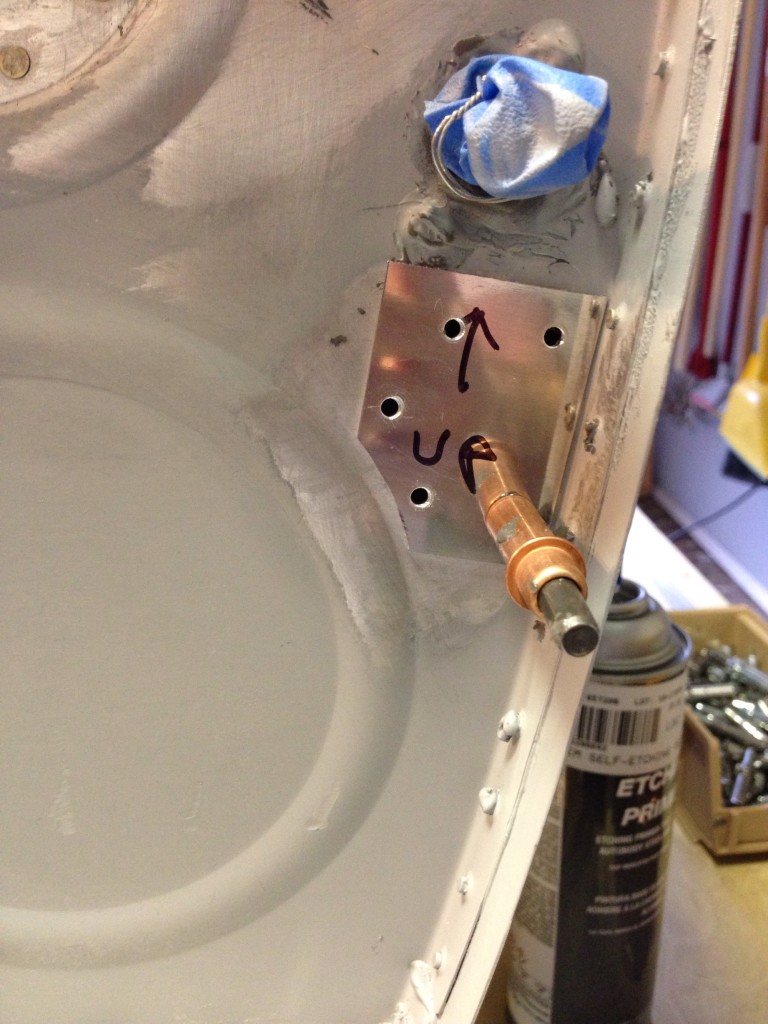
As part of the EFII electronic fuel injection system, a return line needs to be plumbed into each (or one) tank to allow excess fuel to return.  I plan on having a duplex valve, so need a return into each tank.  The problem is the location I, and others, chose was going to be right in front of the spar, thus not allowing any line and or bolt to be installed.   This was going to necessitate removing both tanks and somehow fixing the problem without building new tanks.

img_0421

You can see the return line on the left in the very corner.  Bad place to be.  Some have cut an access hole in the back rib and used a kit from Van’s.  But I hated to introduce so much weight and mess if I didn’t have to.  I decided after a lot of thought that I could get a wrench inside and remove the fitting without too much trouble.

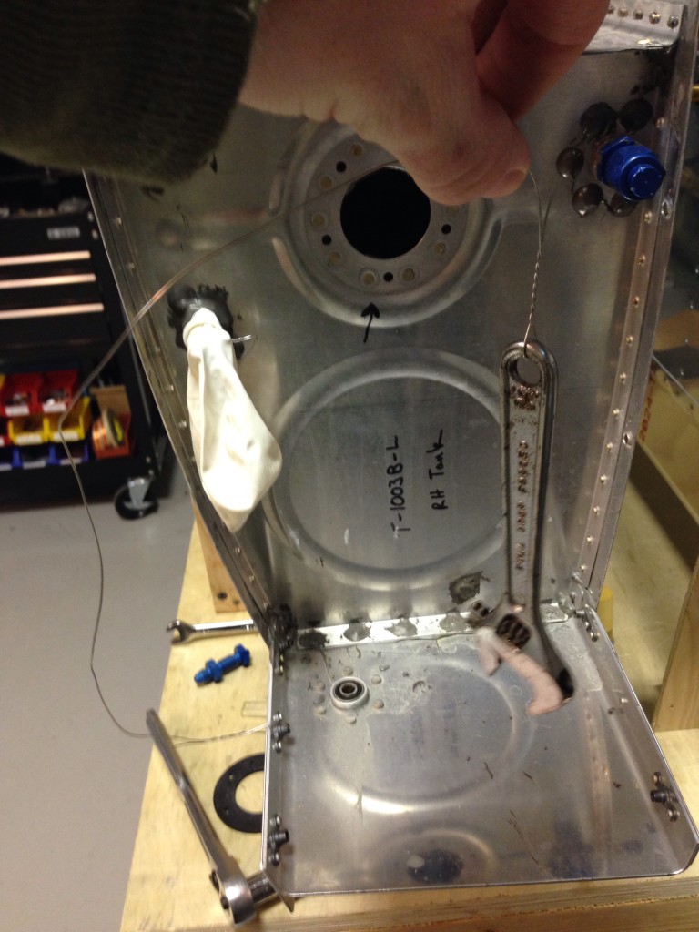
I put safety wire on the wrench so it would not be lost inside the tank and got to it.  With a little patience, I was able to break the tourque and pro seal to get the fitting out.

img_0422

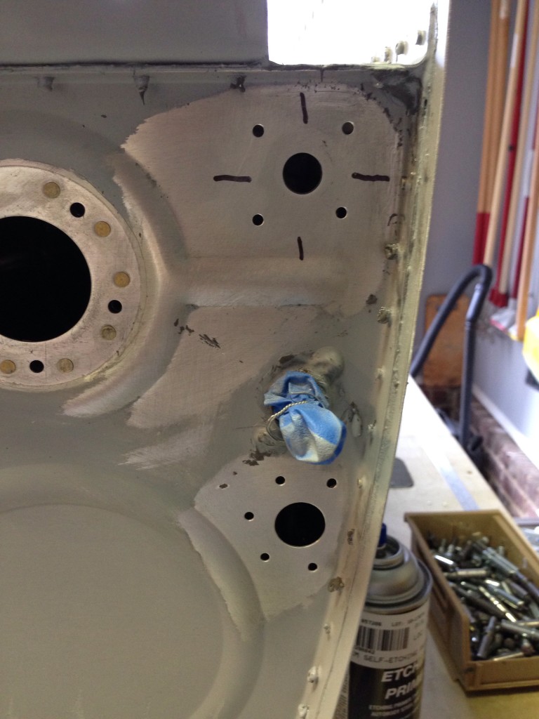
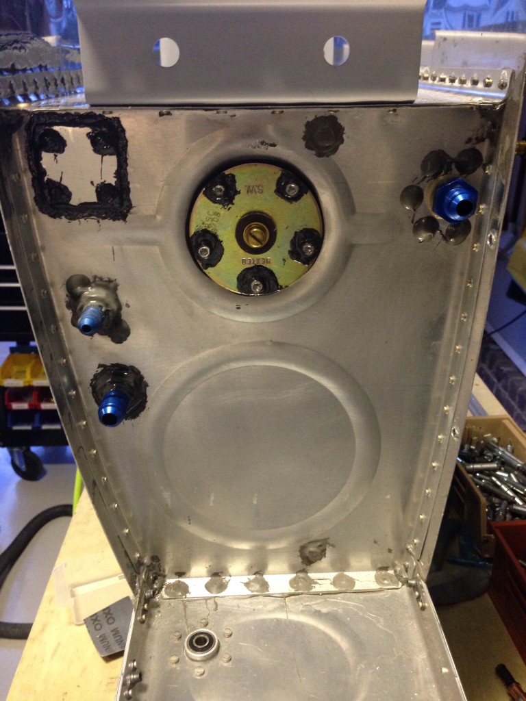
After that, it was just a matter of making a patch for the old hole and properly placing the new hole.  Sounds simple, right? Well, let’s take the opportunity to make it better.  FEedback from EFII was to have a larger fitting for the return line so I ordered the parts and had a brilliant idea of using a left over fuel bong plate.  I thought that would be a nice fitting that I could just screw the fitting into.  Wrong again.  Different threads.  I discovered that after already drilling the holes.  So another patch was in order.

img_0436

img_0439

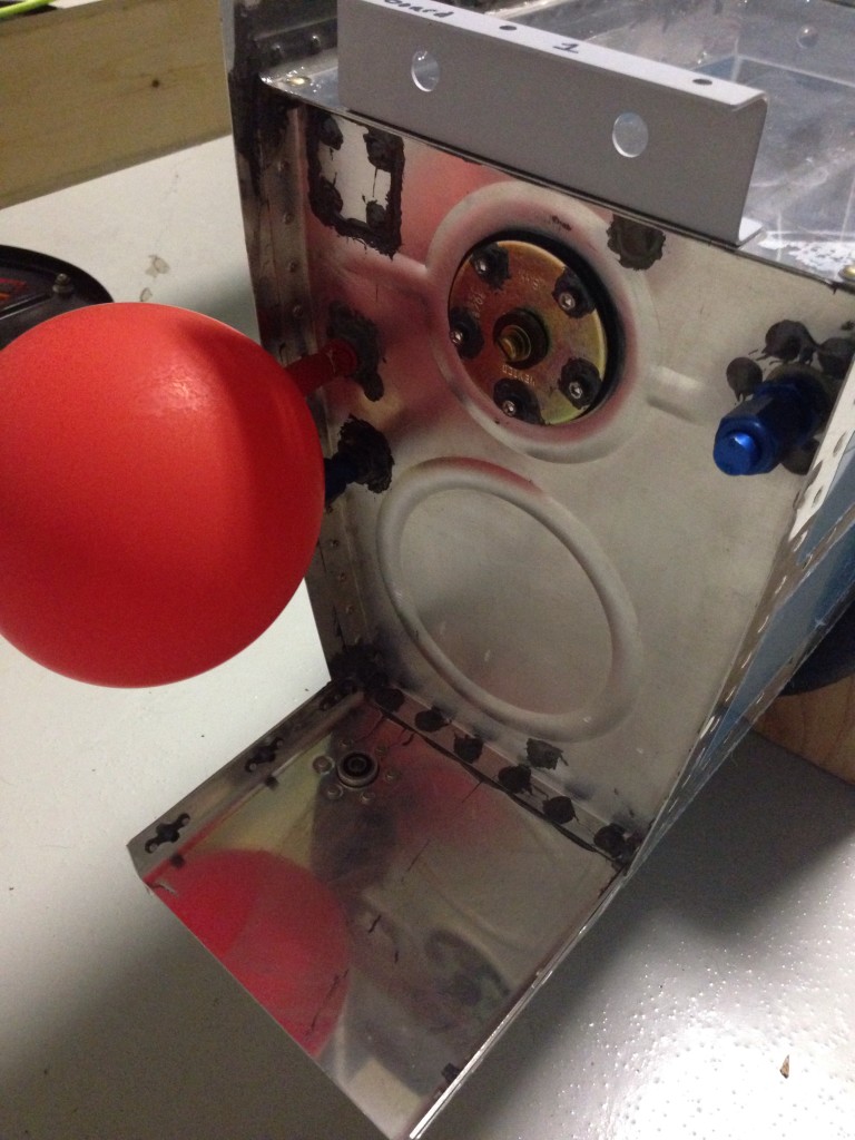
In the end, it was a one evening job and I didn’t have to cut a hole in the tank since I was able to go through the fuel sender hole.  Another two day balloon test with no leaks anywhere on the tank reassured me on the construction.  Finished priming them and back on the wings they go, hopefully this time for good.

img_0447

img_0460