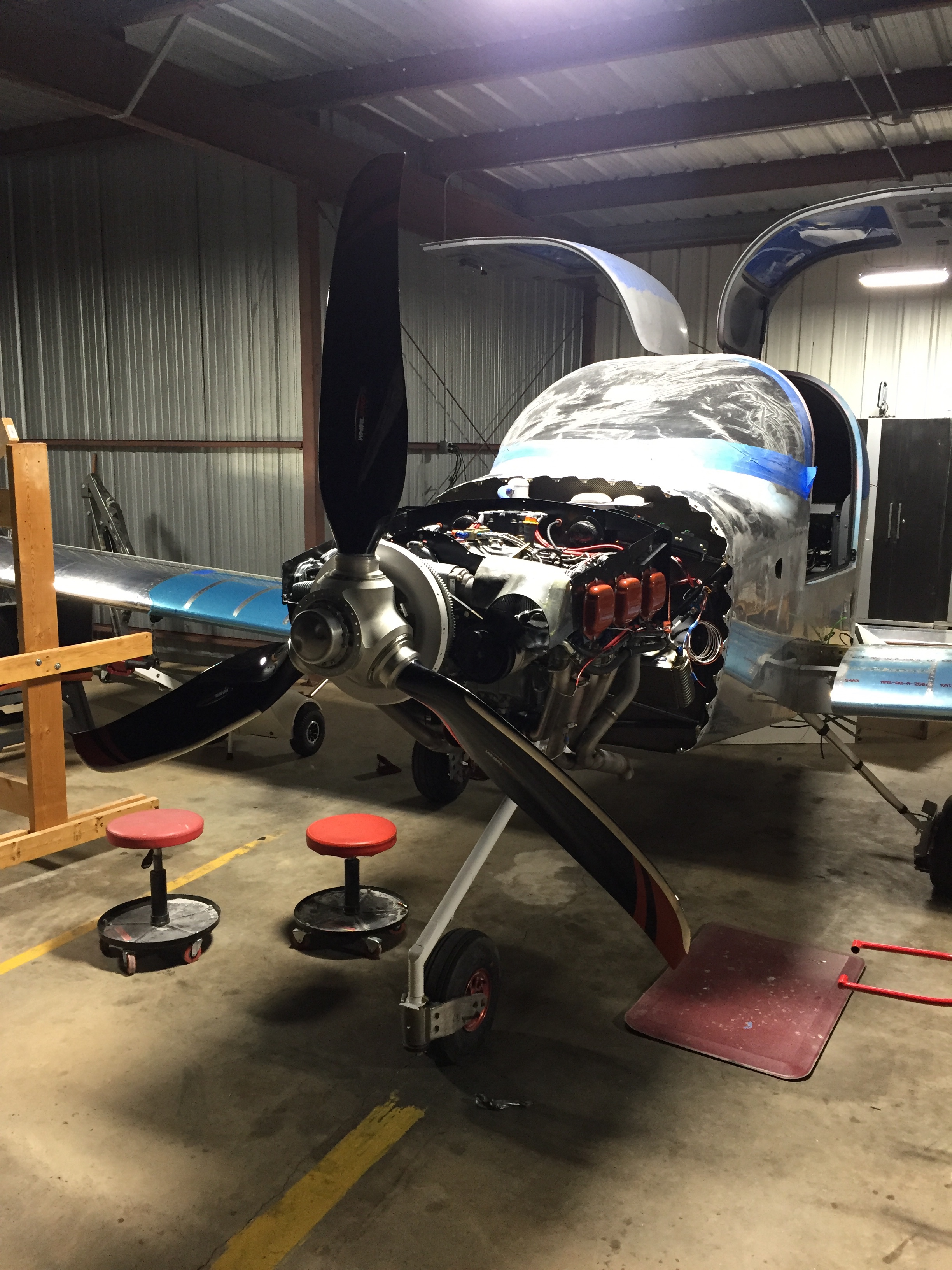
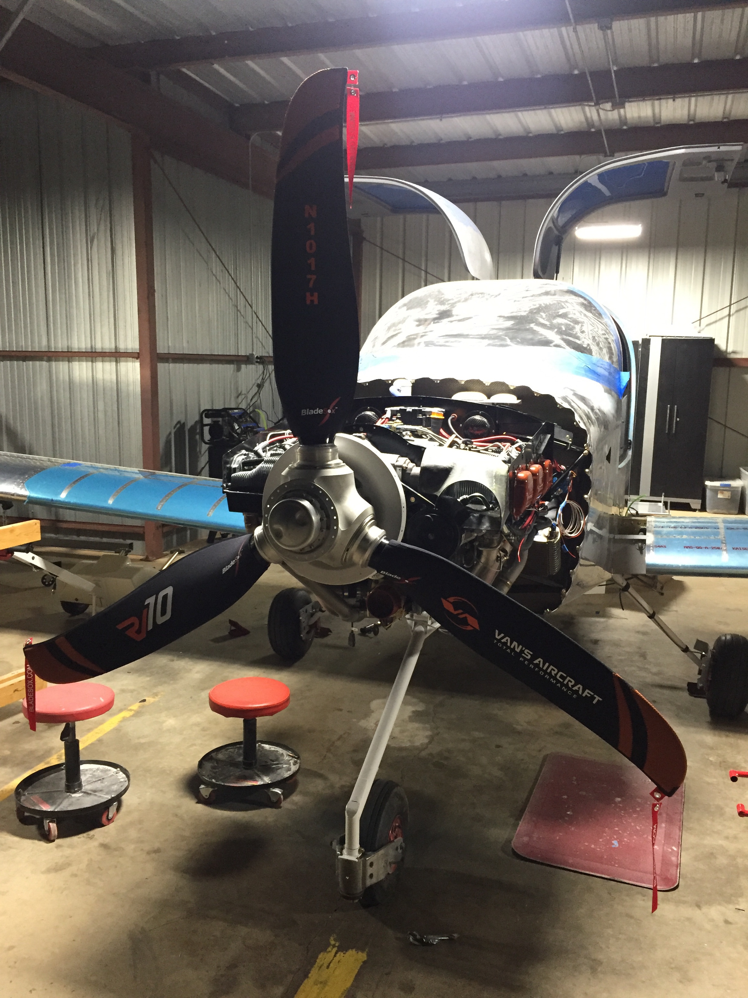
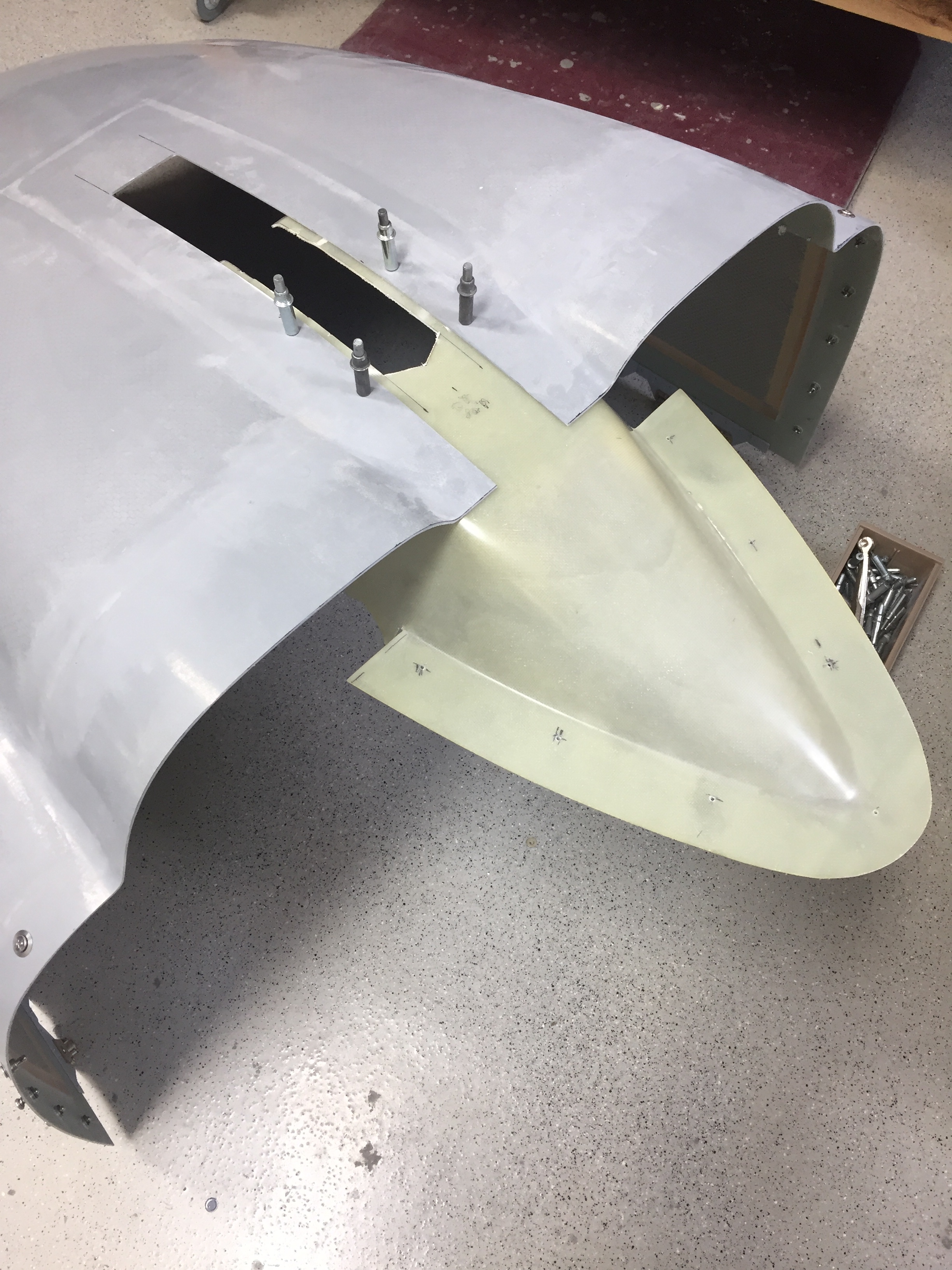
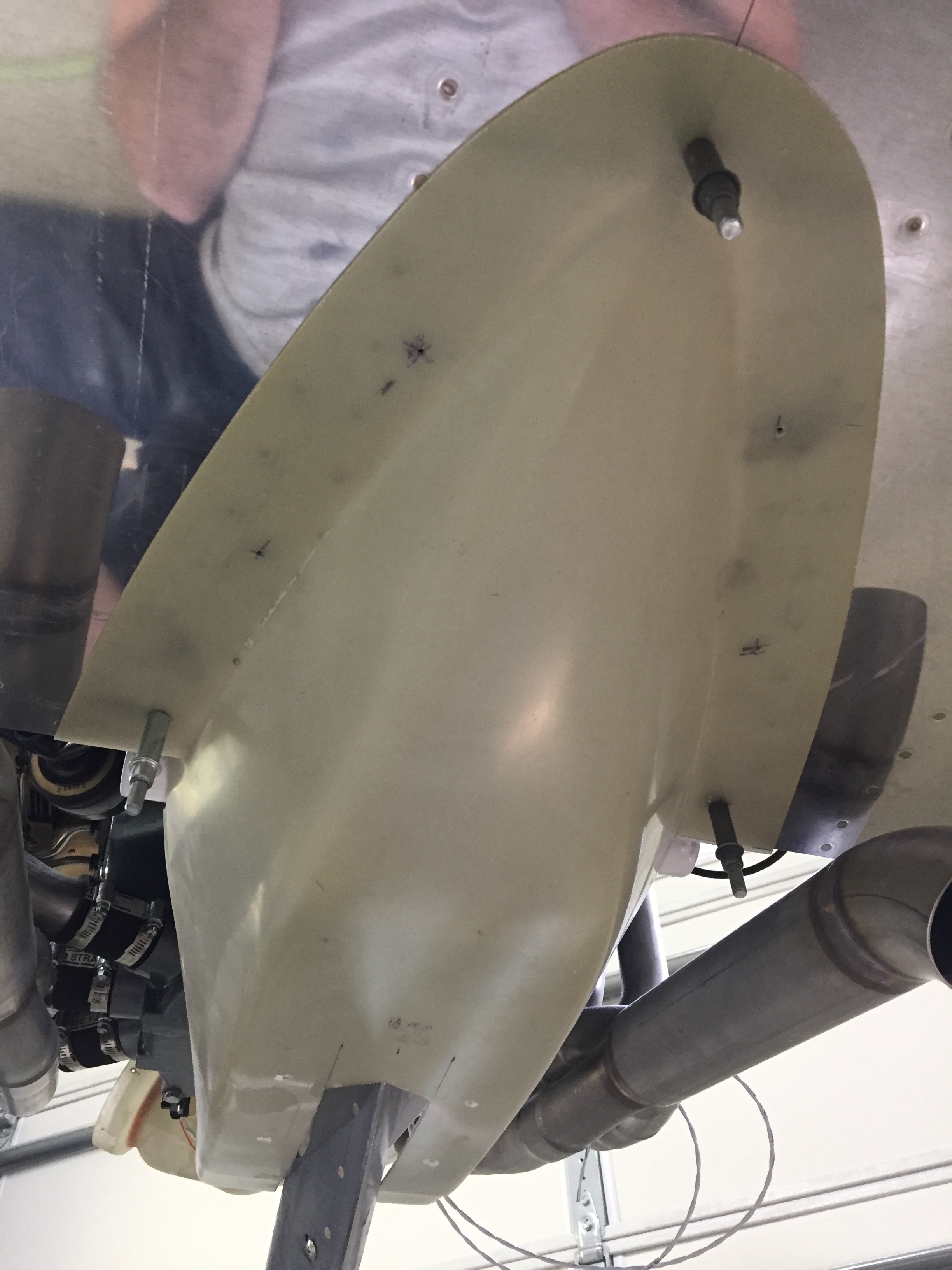
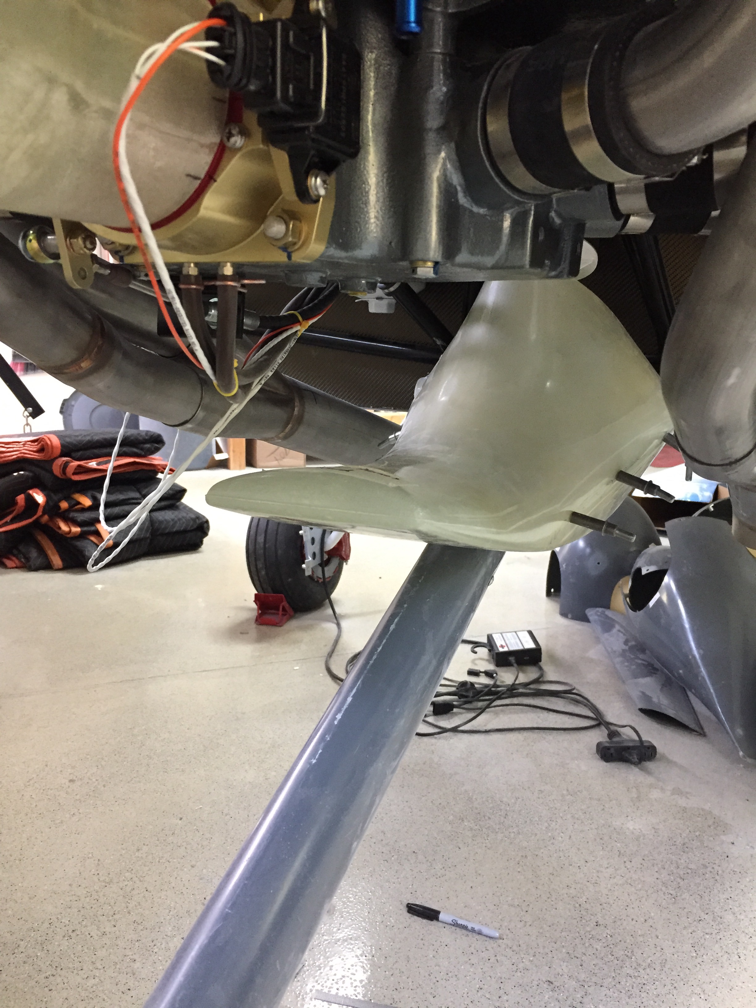
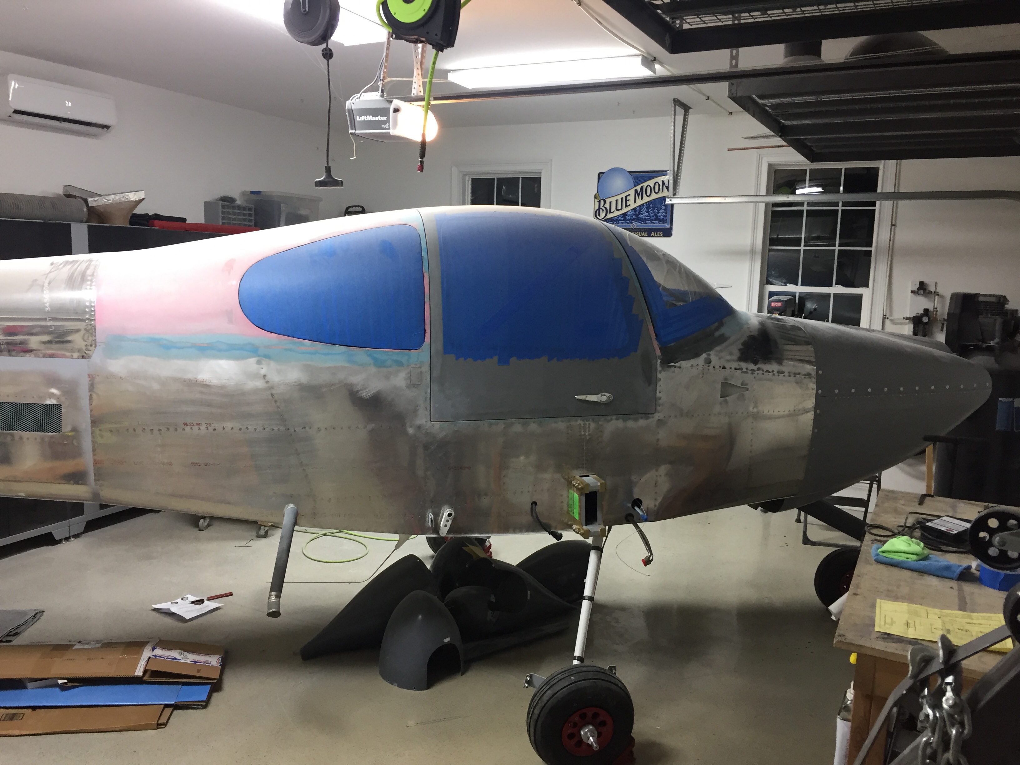
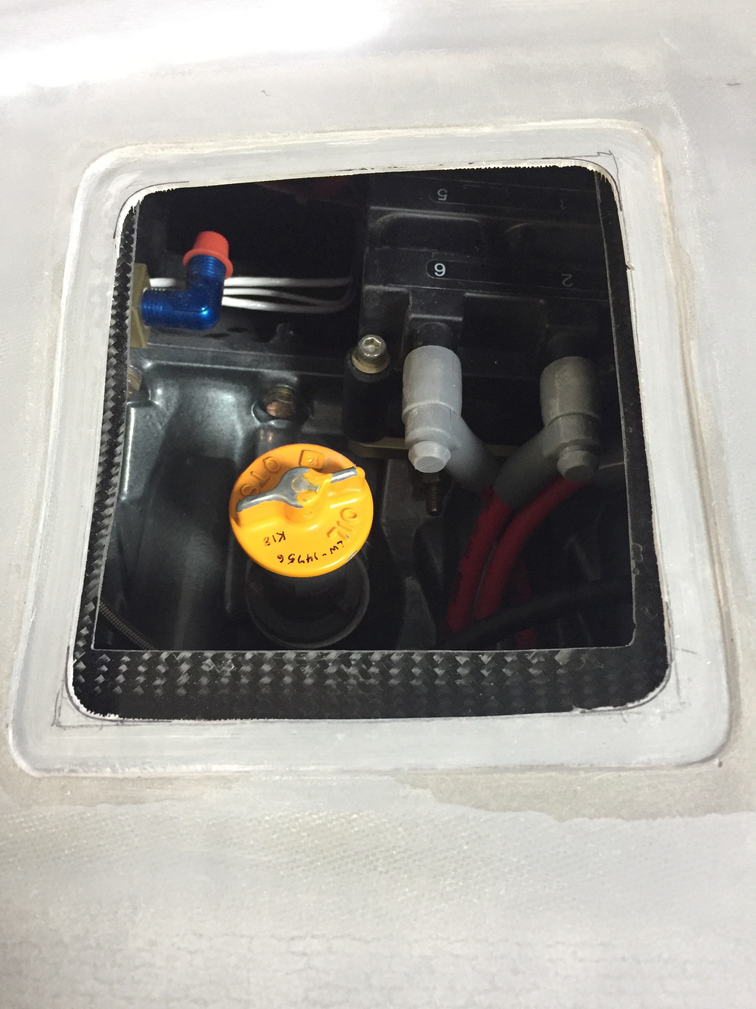
Now the cowling is fit, some tricky bits come up on the to-do list including the engine intake ducts and cooling ducts. All of these are complicated by my air conditioning and plenum choices. If I get it right, it’ll be magic and a work of art. I probably won’t get it right the first time, as some of you may have guessed. I started with getting the engine intakes started. These start at the cowling openings and form the bottom 1/4 of the opening. they curve inward and join a Y that holds two K&N air filters before hitting the throttle body. The ducts are well molded and nice light but strong fiberglass. The problem is they don’t fit very well with the exhaust and other accessories on the engine. The Show Planes instructions leave a lot to be desired, but once you piece the components together, it starts to make sense.
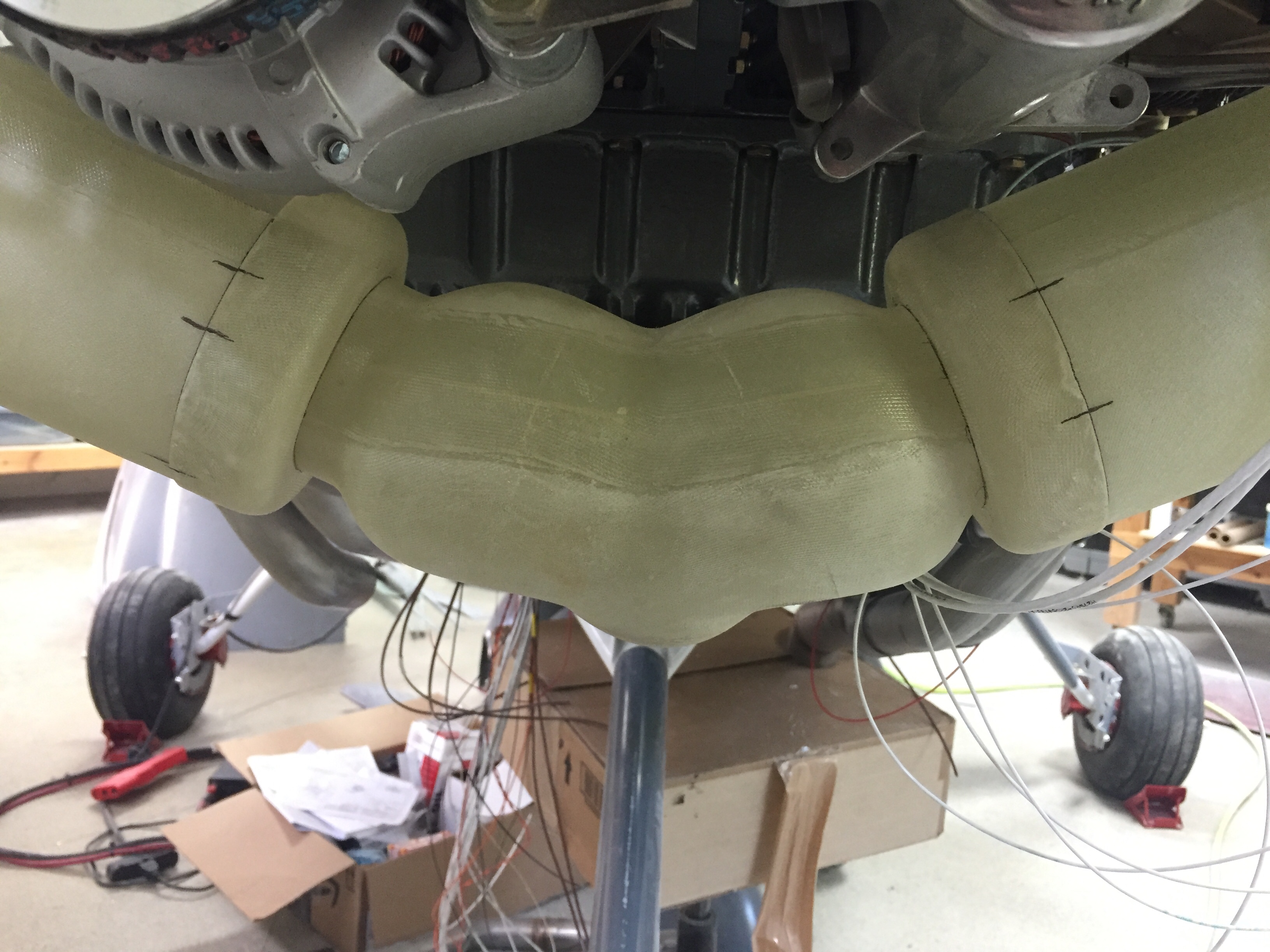
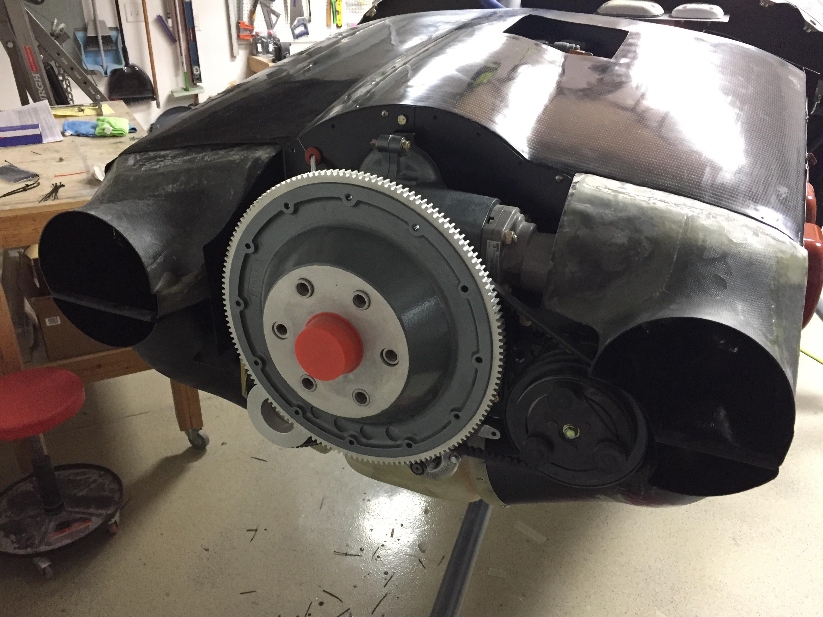
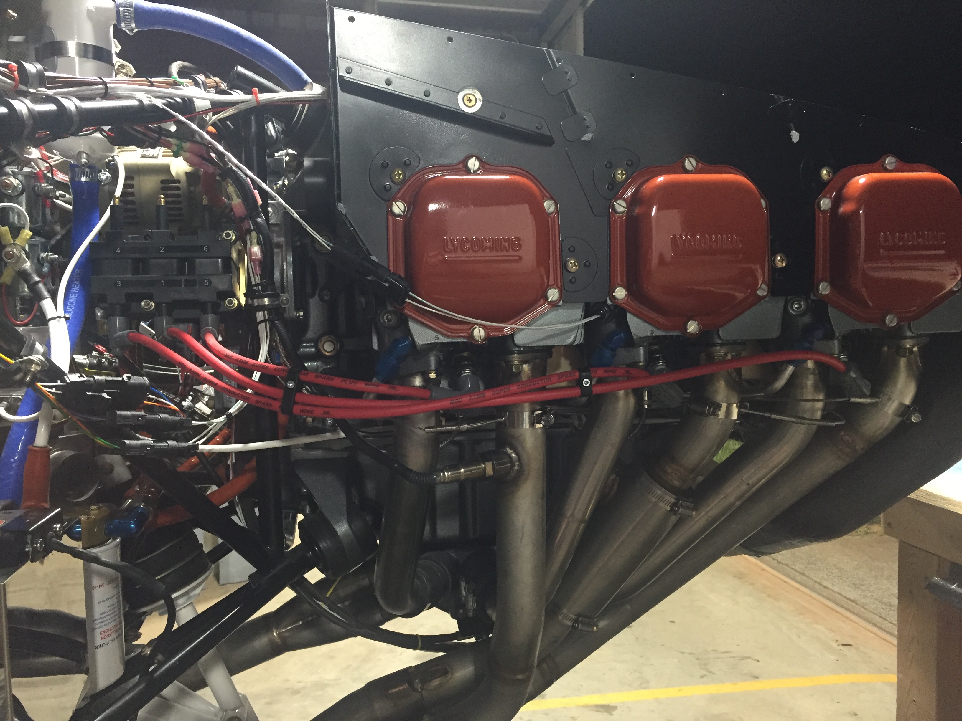
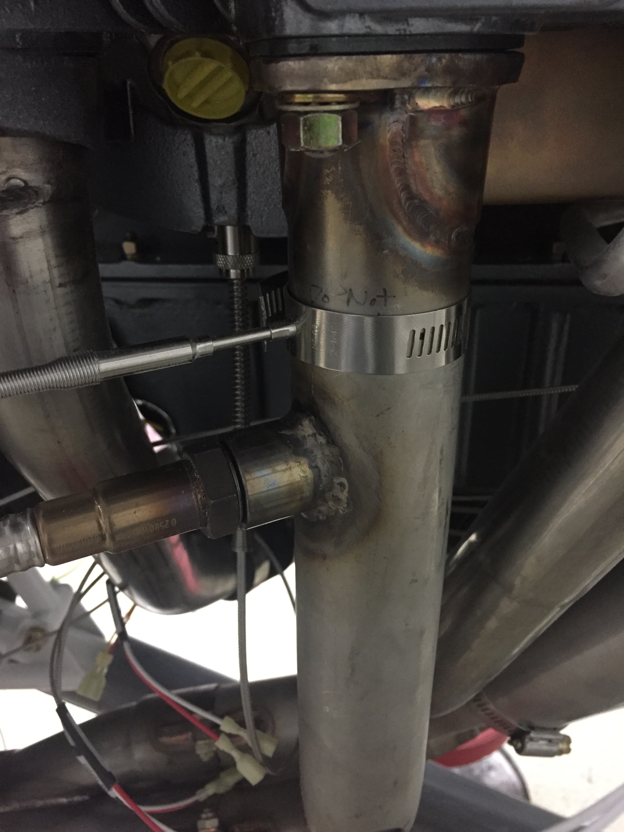
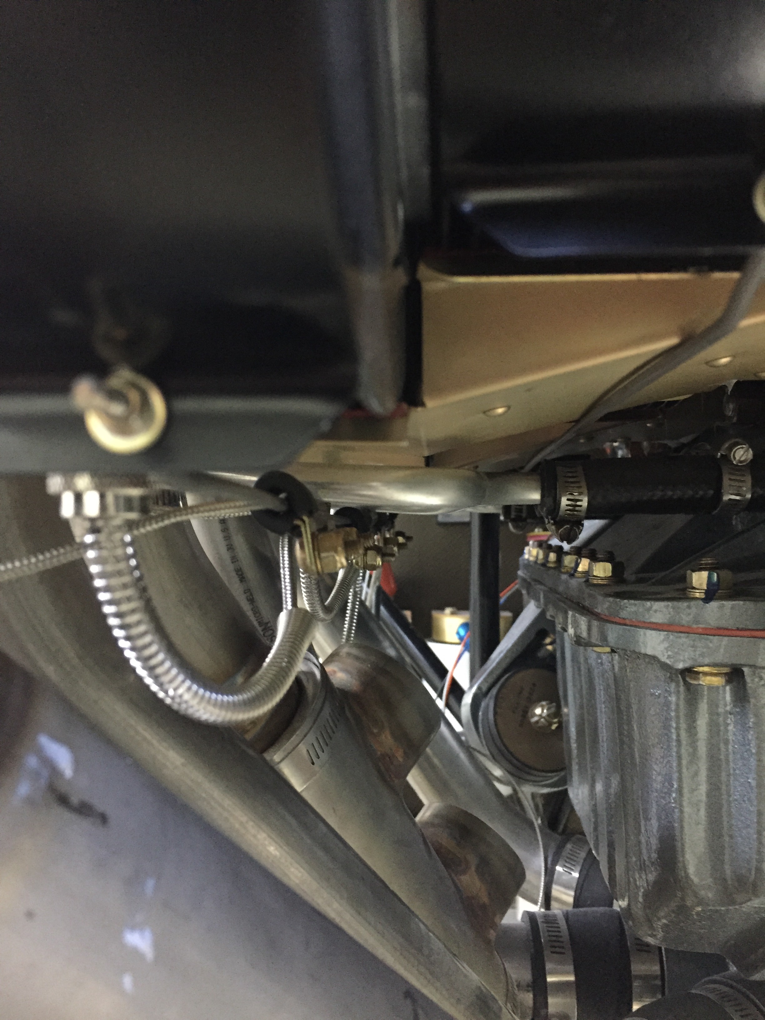
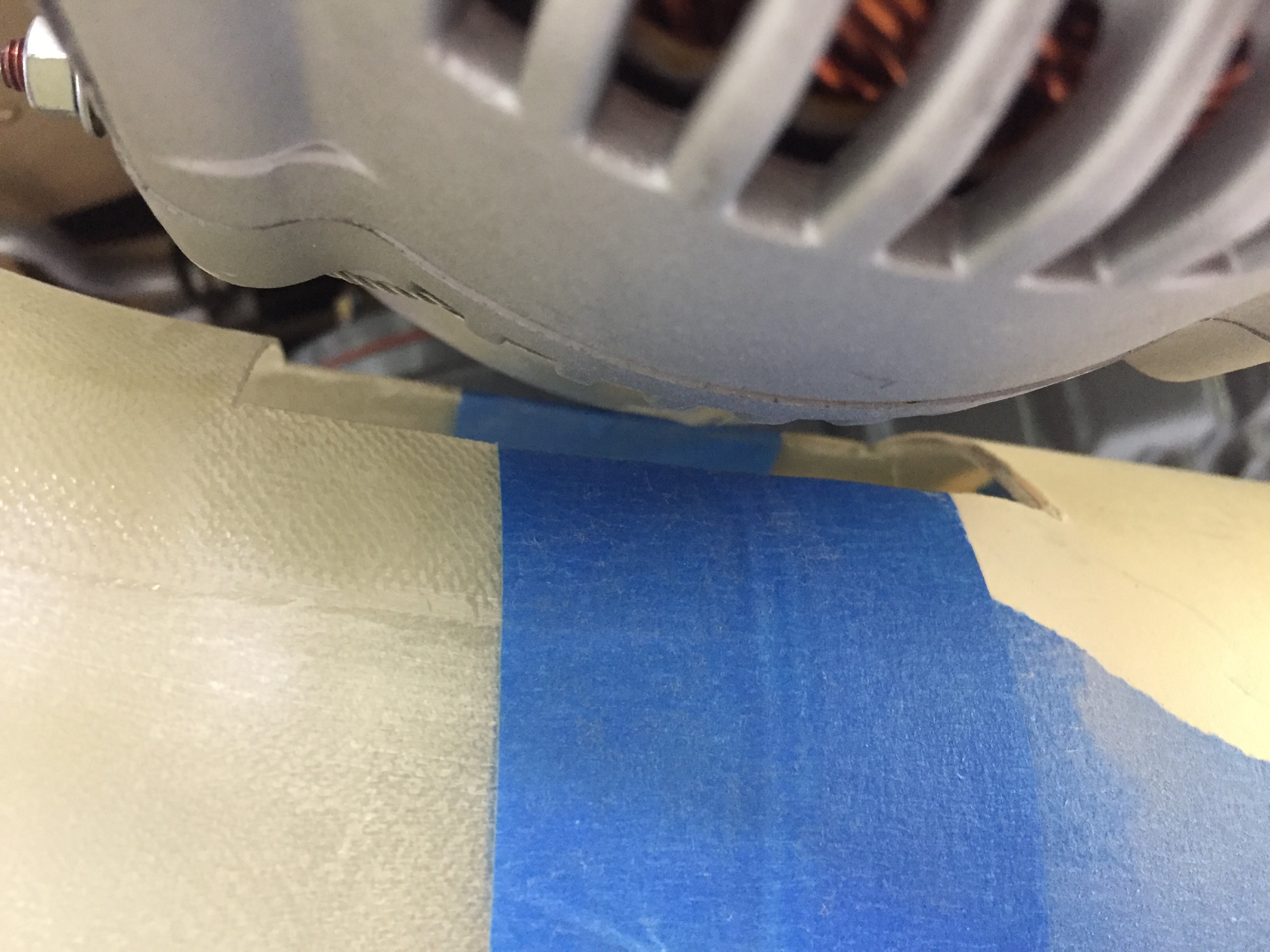
I first had to cut a relieve for the alternator. Not sure if it’s just the Plane Power or if all alternators will require this, but mine was about a 1/2″ too low impacting the right duct. Next, I had to trim quite a bit for the exhaust coming from #2 cylinder. I tried to get a good 1/2″ to 3/4″ clearance and will using some heat shielding to protect it from the close proximity.
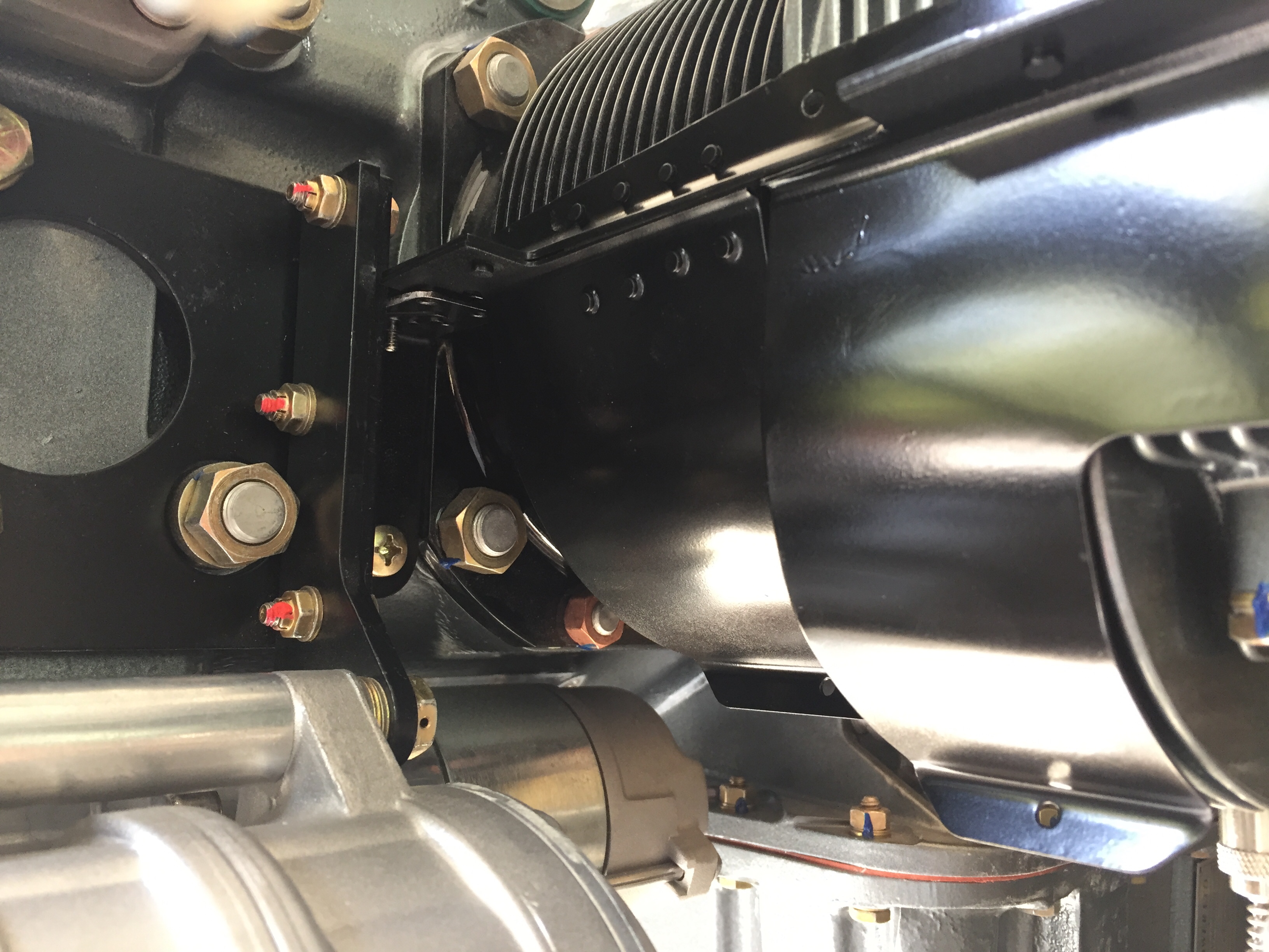
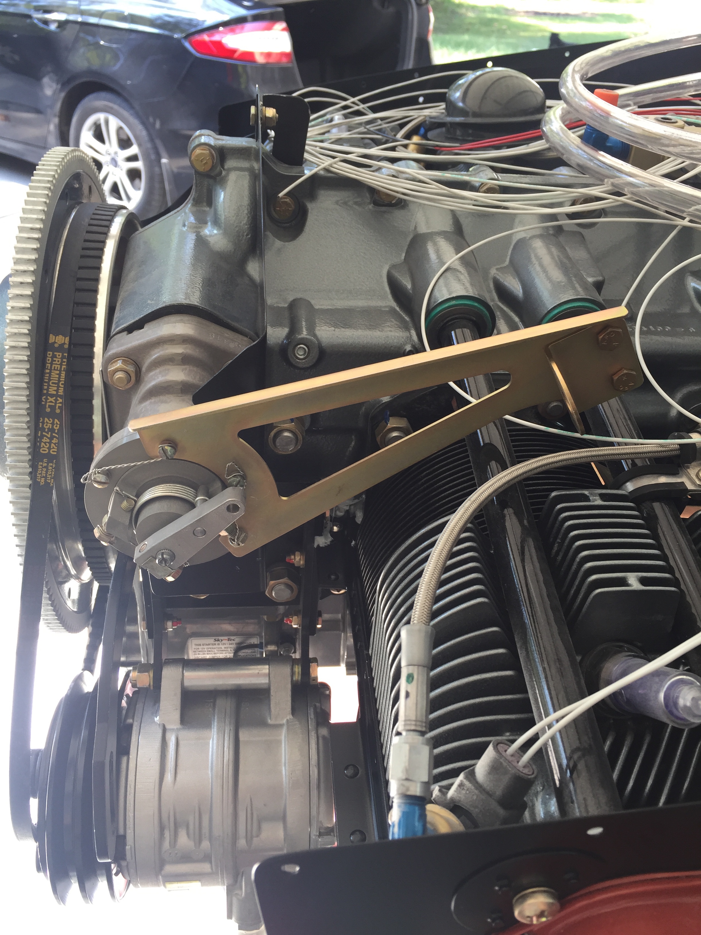
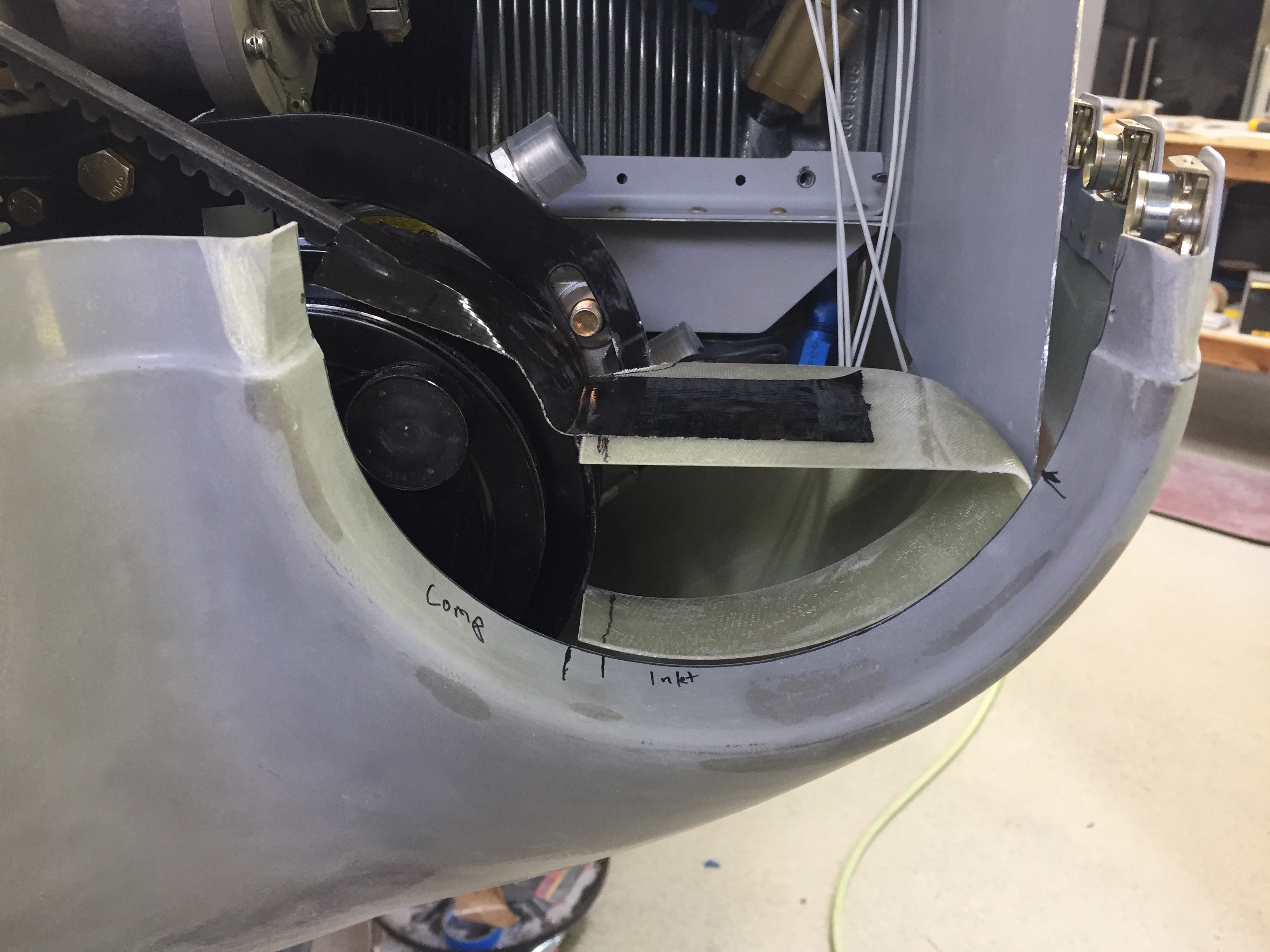
On the left side, the air conditioning compressor dictates a much larger modification. Gaylon wound up elimintating this duct all together but I want to at least try to keep it. The problem is the compressor blocks some of the cowling opening and thus reduces not only intake air flow but cooling air flow. I’m hoping since I have a plenum and will have the cooling intake completely sealed, that the minimum reduction won’t interfere with adequate cooling. Time and testing will tell. I also want to keep the left side induction to maximize manifold pressure thus power and performance of the engine as well as keep the redundant induction air supply (think alternate air on the stock setup).
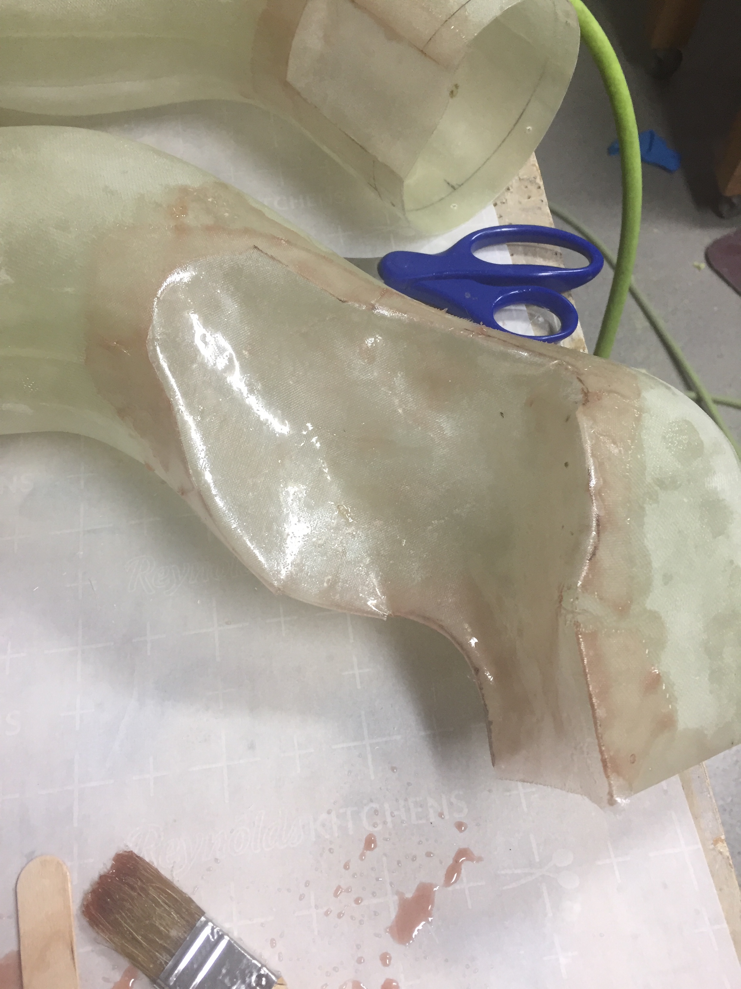
I had to notch out a few spots to create clearance around the compressor and mounting bracket. Once I had the areas trimmed away and fit properly, I laid up fiberglass by hand to enclose the reliefs. I debated on creating a mold or plug type thing but determined it’d be next to impossible for me since I’m not good at it anyway. Plus I tried one of them and was pretty happy with the results, so why make it more complicated? I did two layers of glass then a third on the inside. I honestly don’t know what weight it was, but it’s very thin thus the three layers added up to about the same thickness as Show Planes had with the same rigidity.
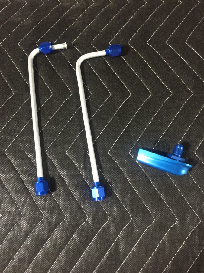
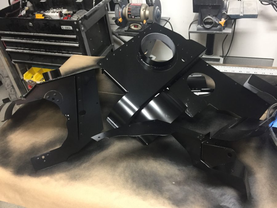
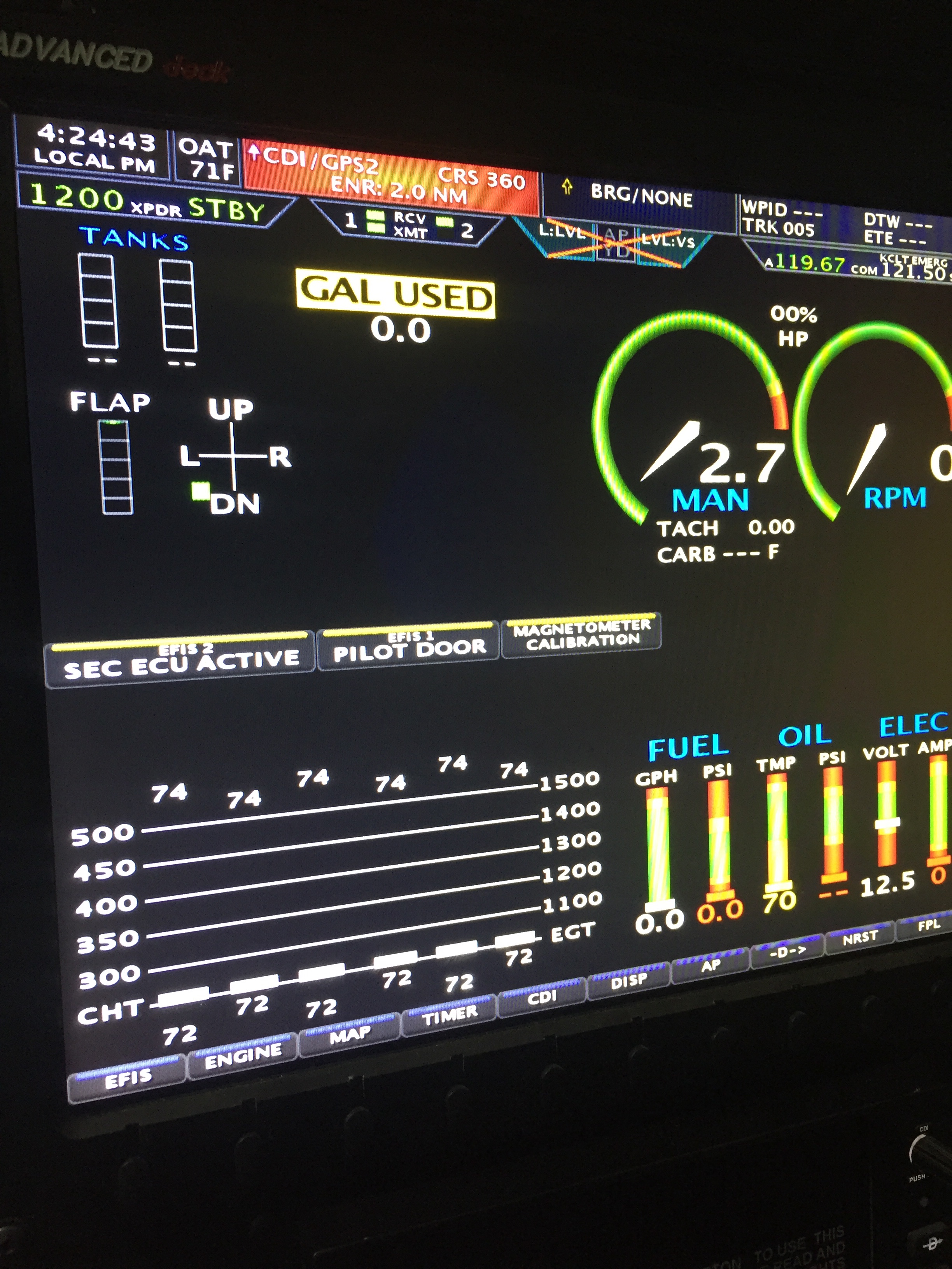
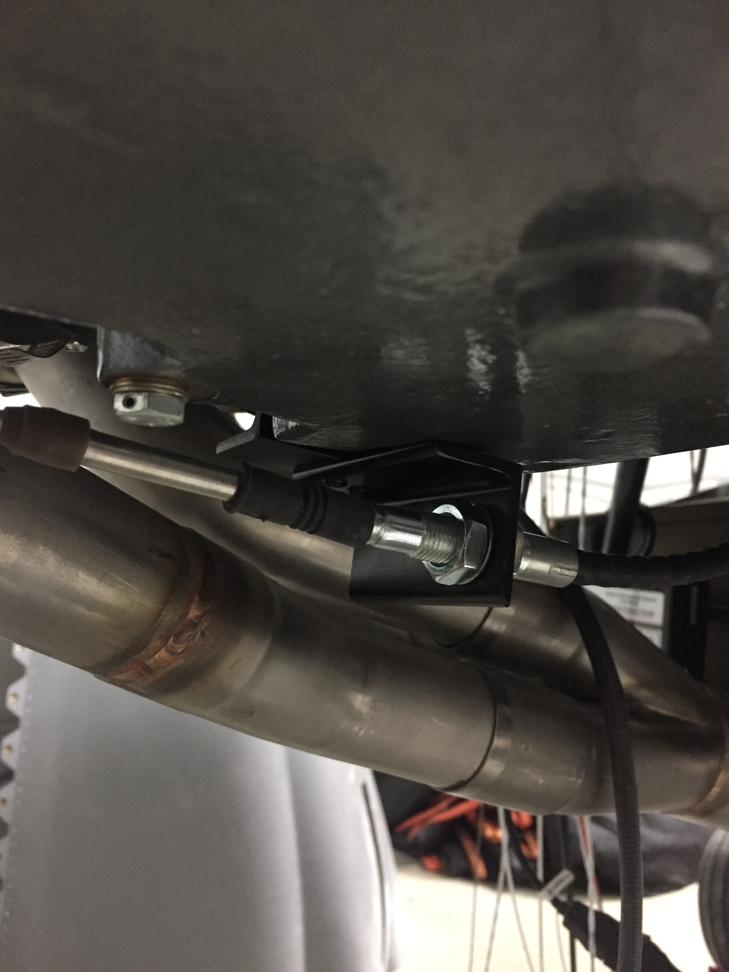
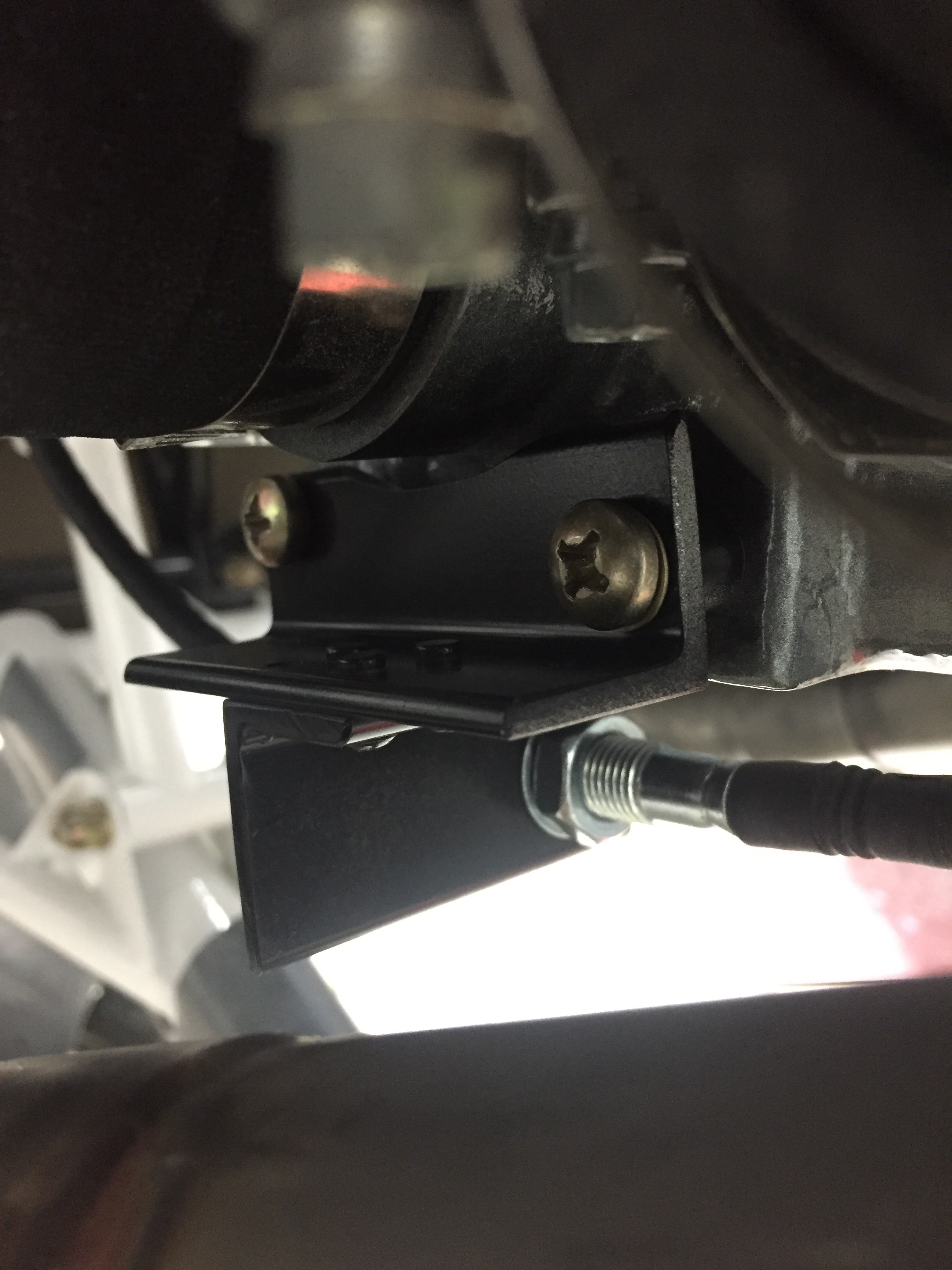
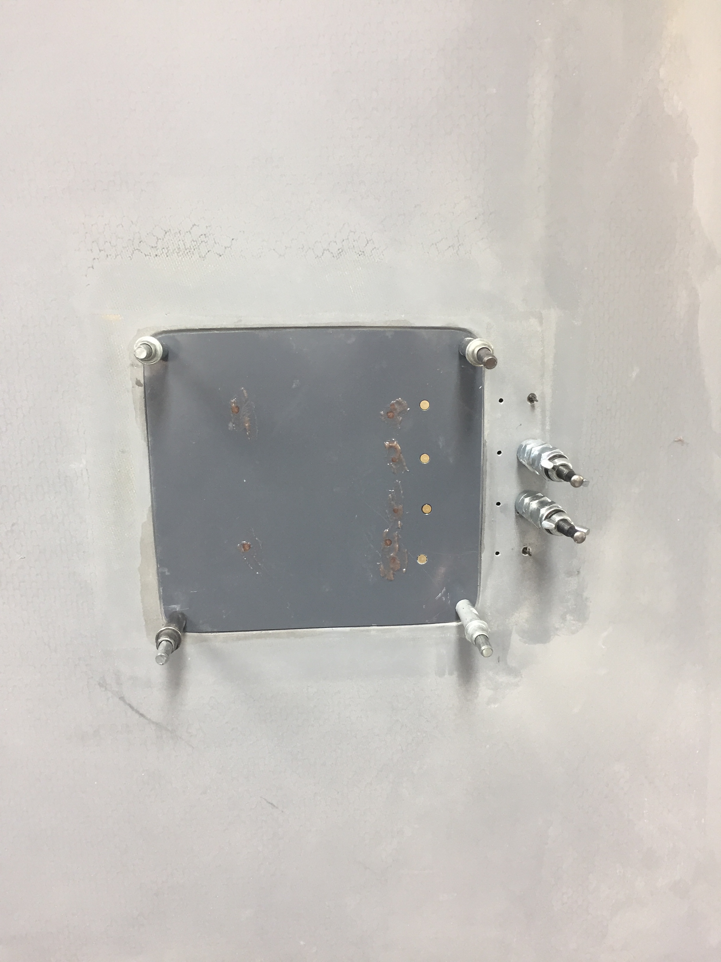
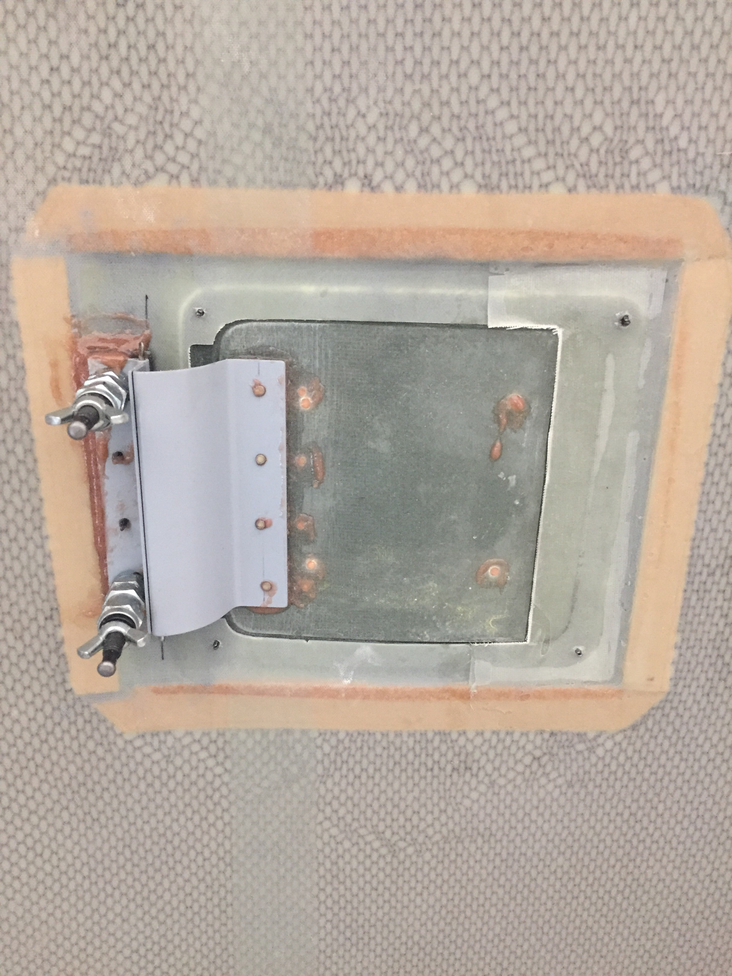
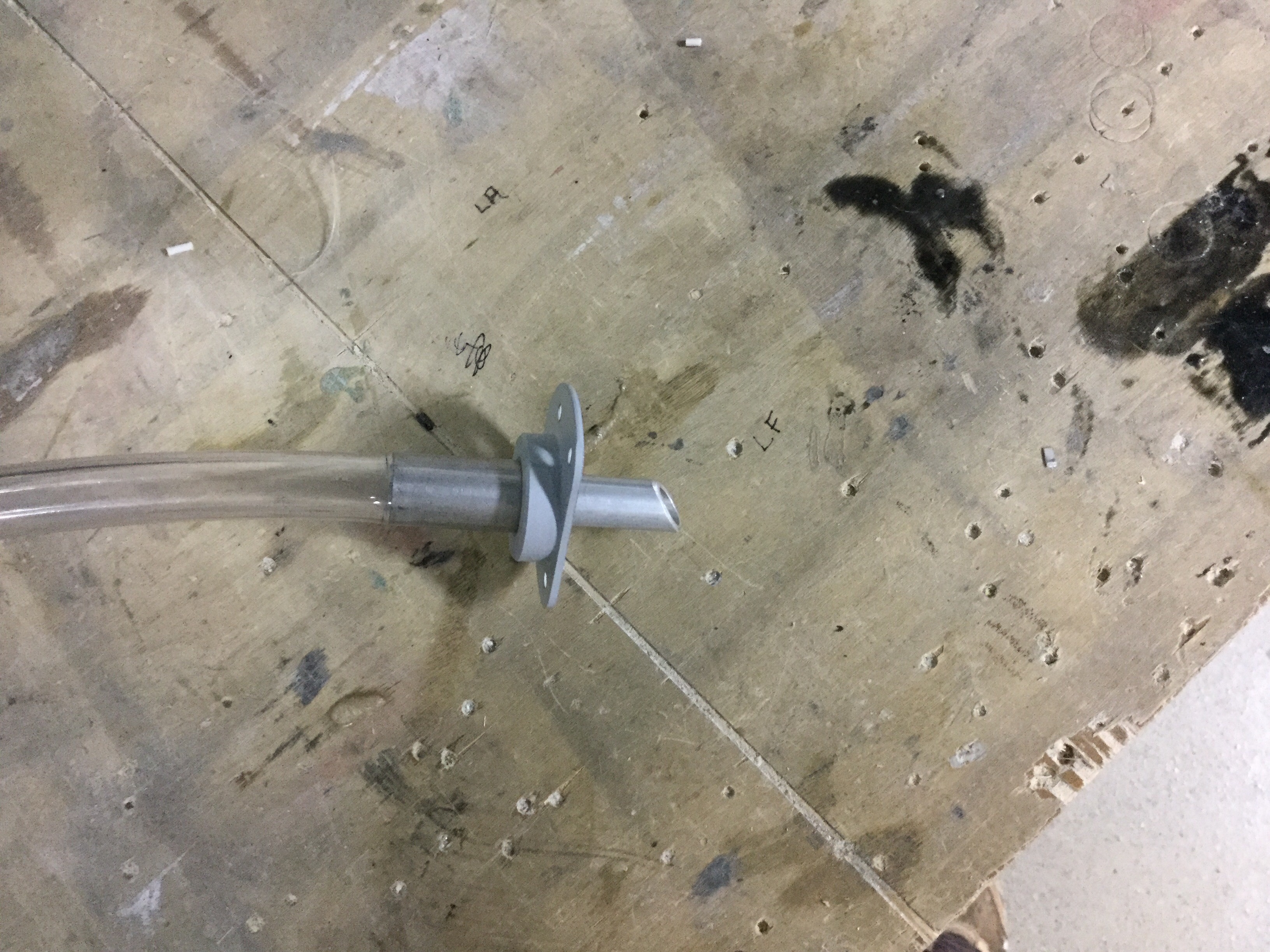
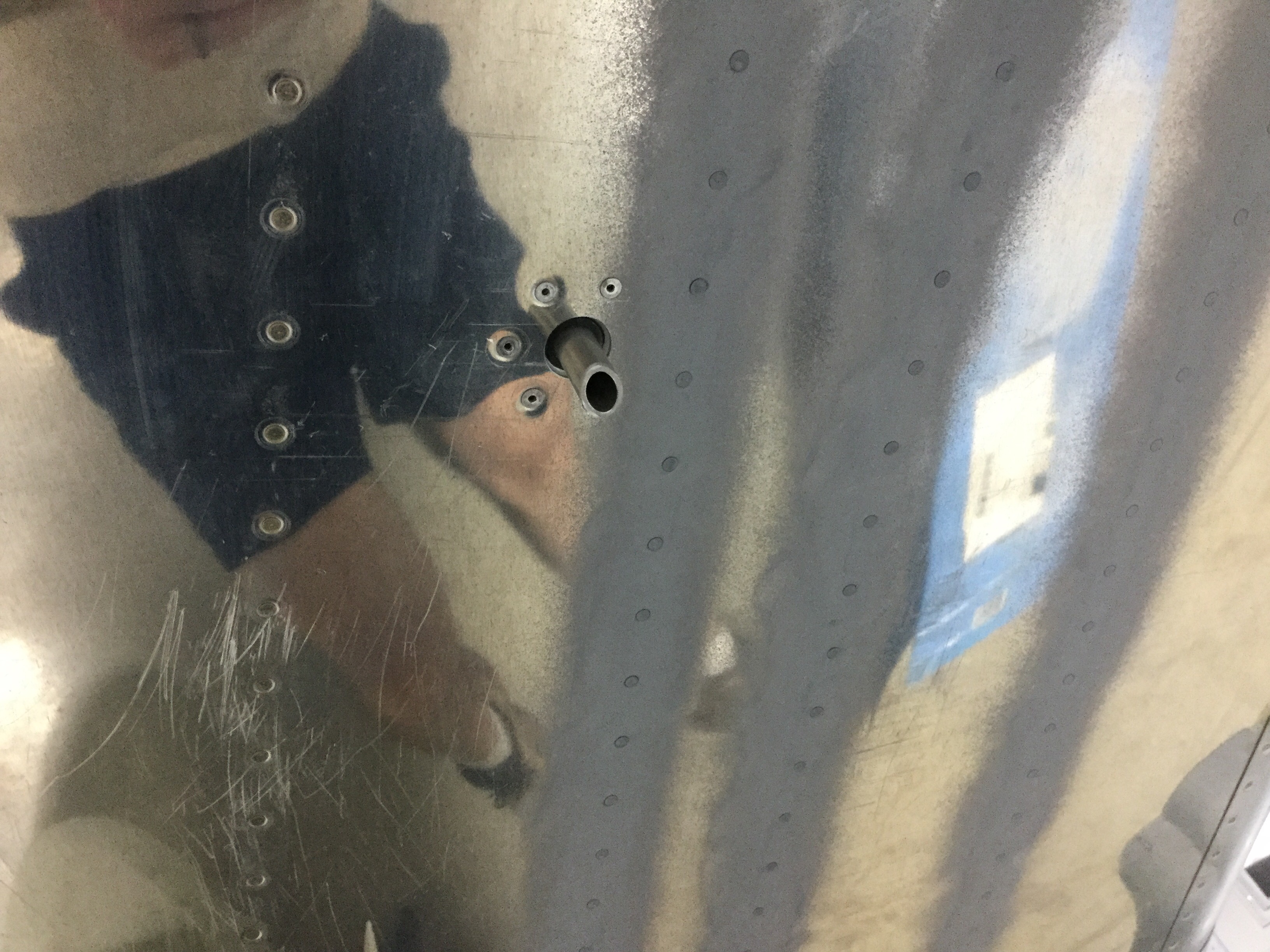
A bit of sanding and trimming, and everything with the ducts were finished up. I painted them black just to hide them inside the cowling a bit and because I wanted to. The last two sensors to install for the engine are intake temperature sensors that I had mocked up and ran wire to but not yet permenantly installed. I bolted those on and sealed them with RTV to avoid air pressure loss. I also drilled the required water drain holes just below the air filters at the lowest part of the intakes.
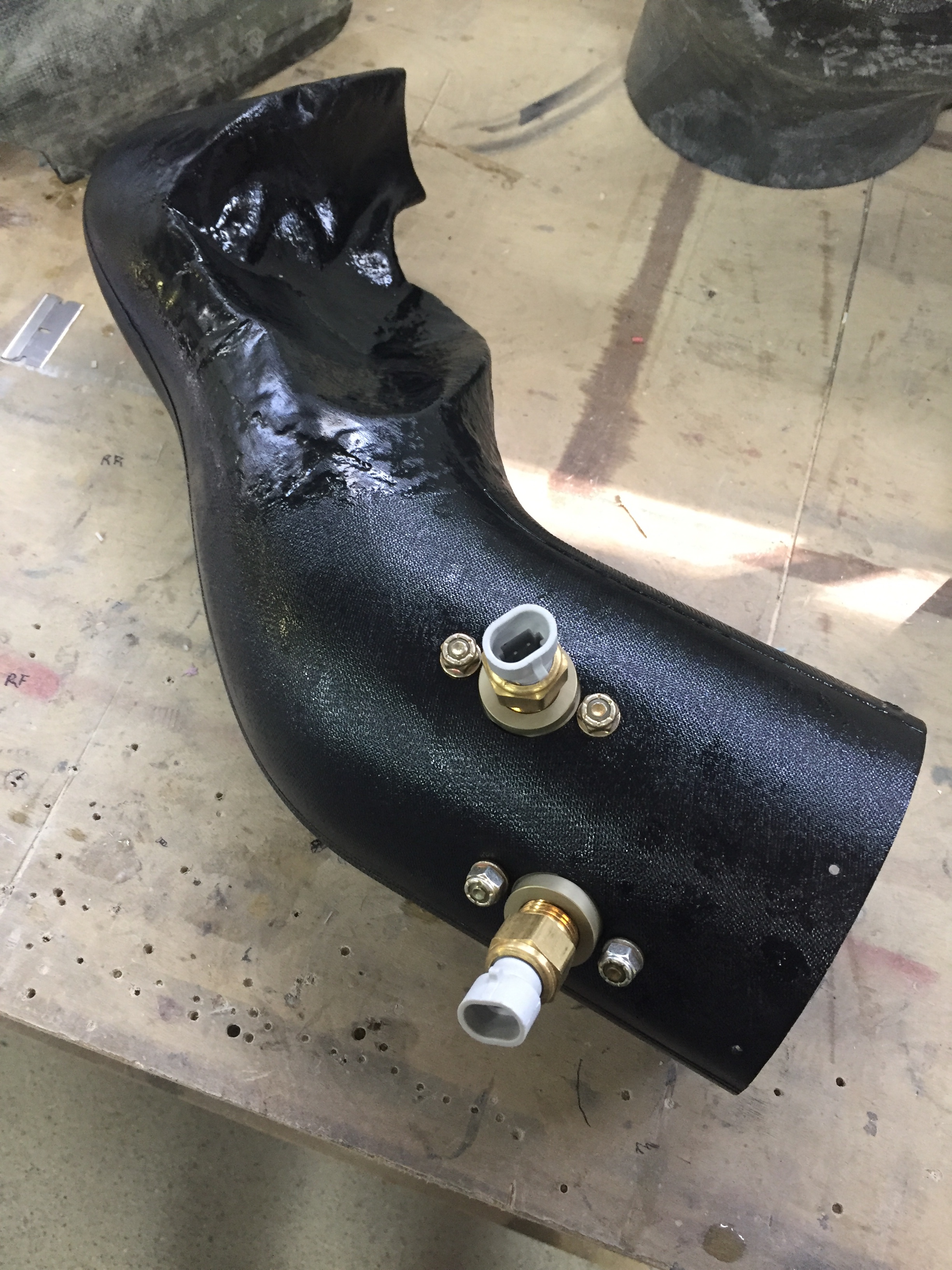
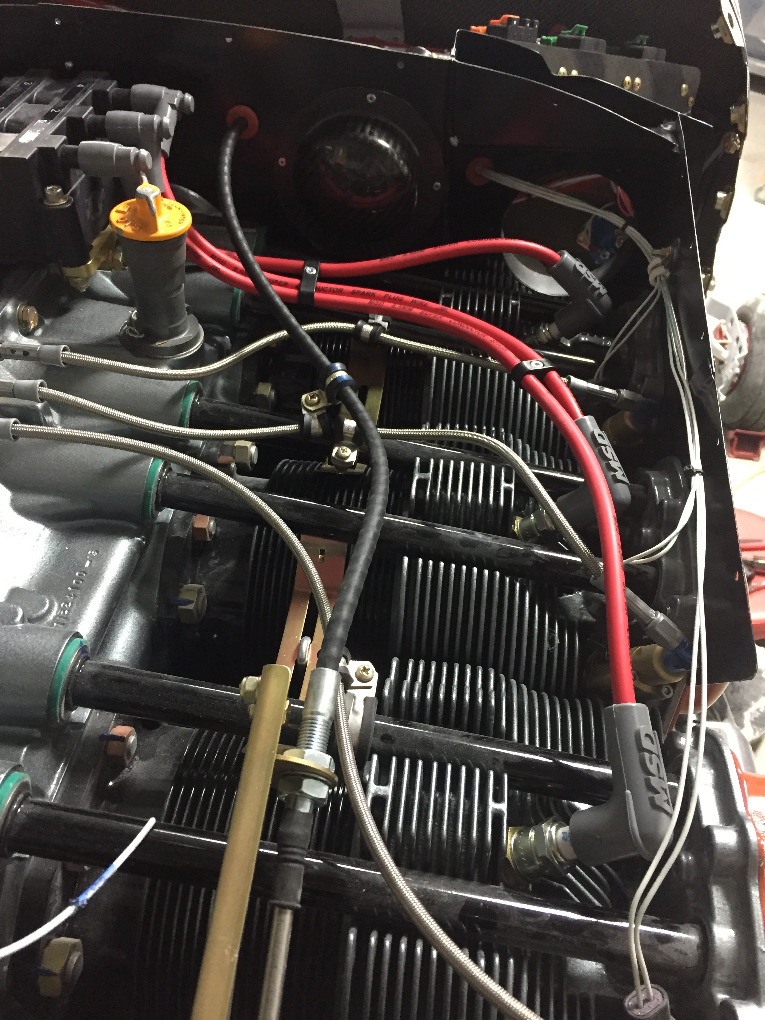
It all sounds so simple now, but trust me, I spent many hours thinking, debating, looking, thinking some more, and finally working out the fit of the ducts and getting a solution that I am happy with. These were just a warm up for the cooling ducts! Show Planes have you modify the stock baffle ramps and provide upper cowling ramps to be epoxied to the cowl to help guide airflow into the engine baffles. Since I am using the plenum, I need to keep air going from the openings to under the plenum. I had originally invisioned carving foam and creating a mold, but once I got busy working, carving foam was going to be next to rediculously impossible. It’d take me weeks just to do the molds. So, I took another approach, use what I had on hand and don’t reinvent the wheel.
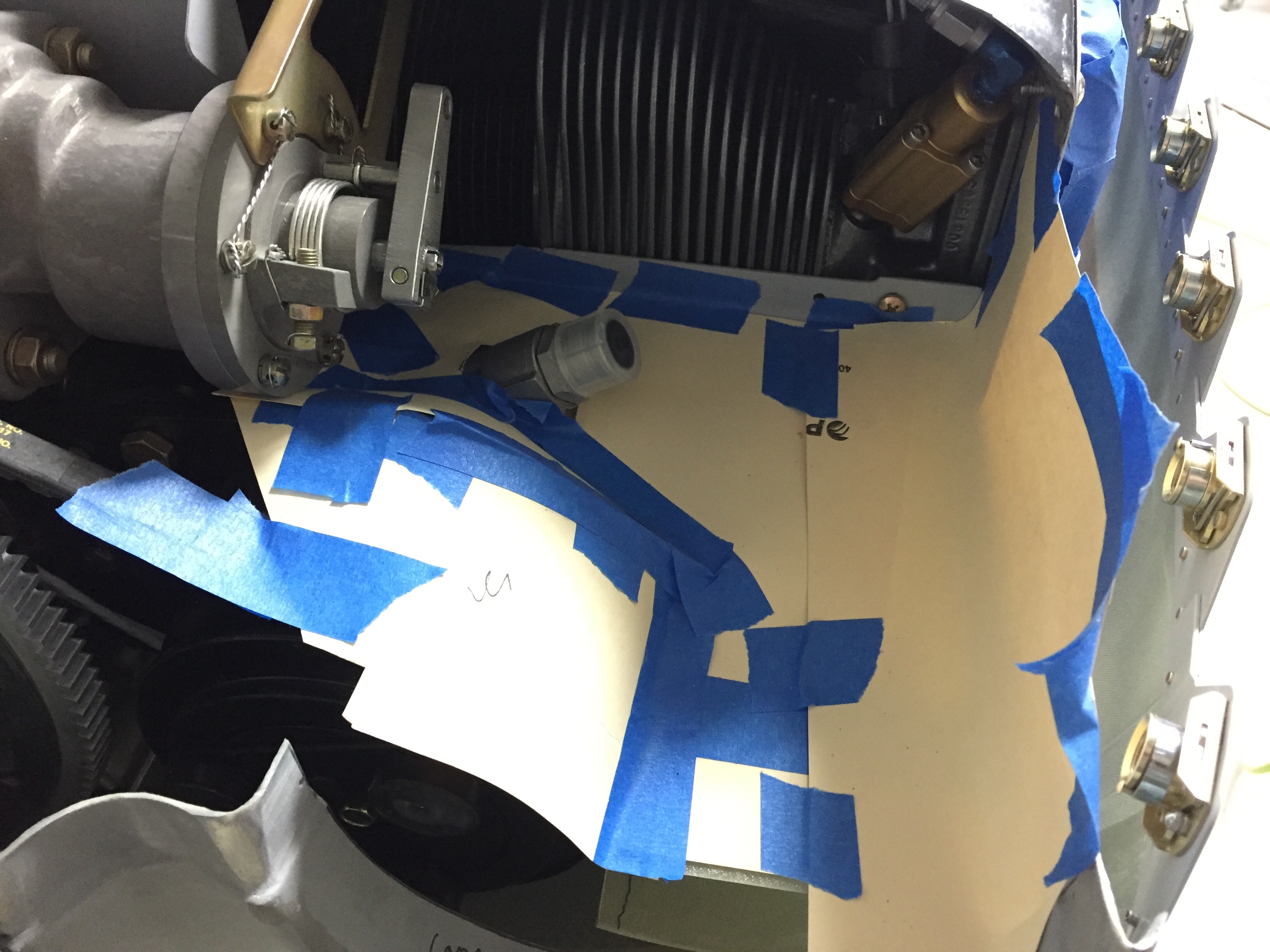
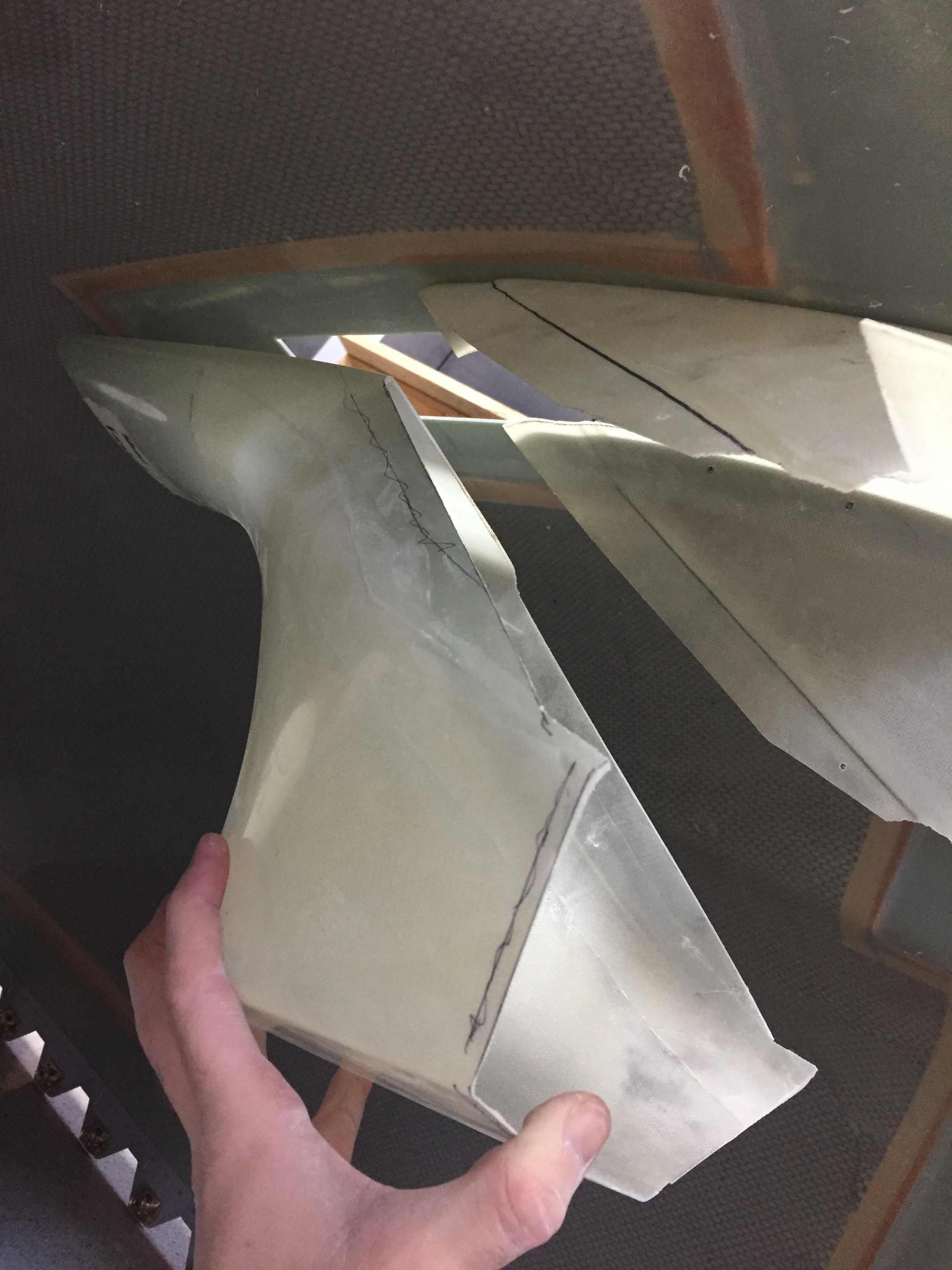
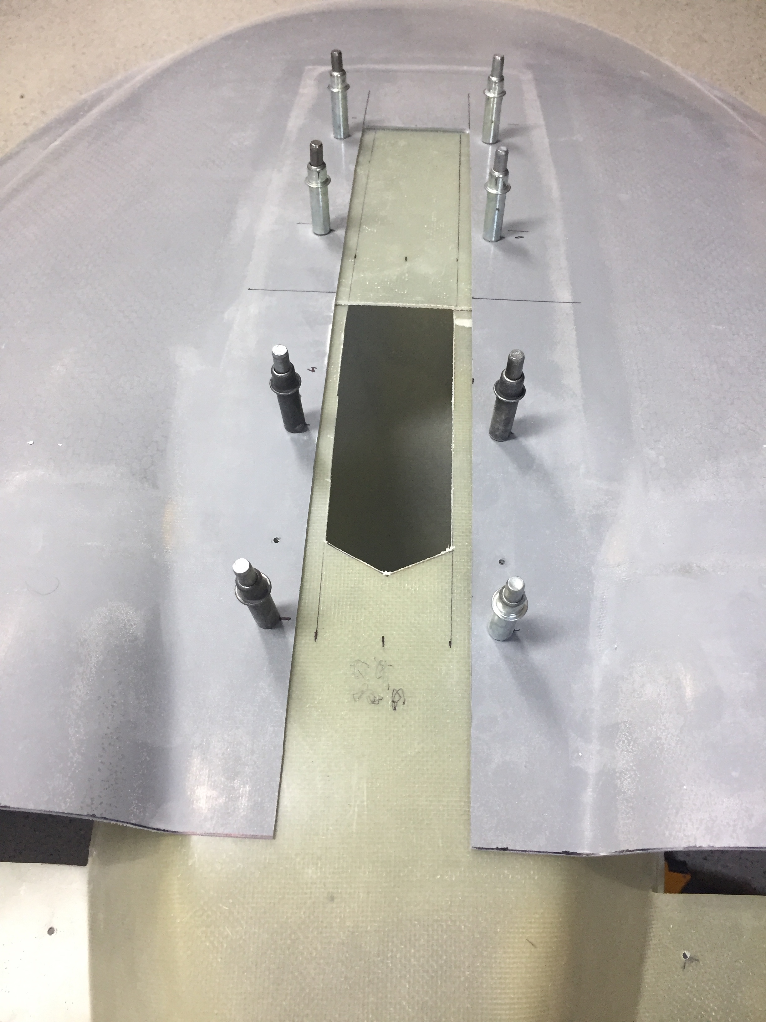
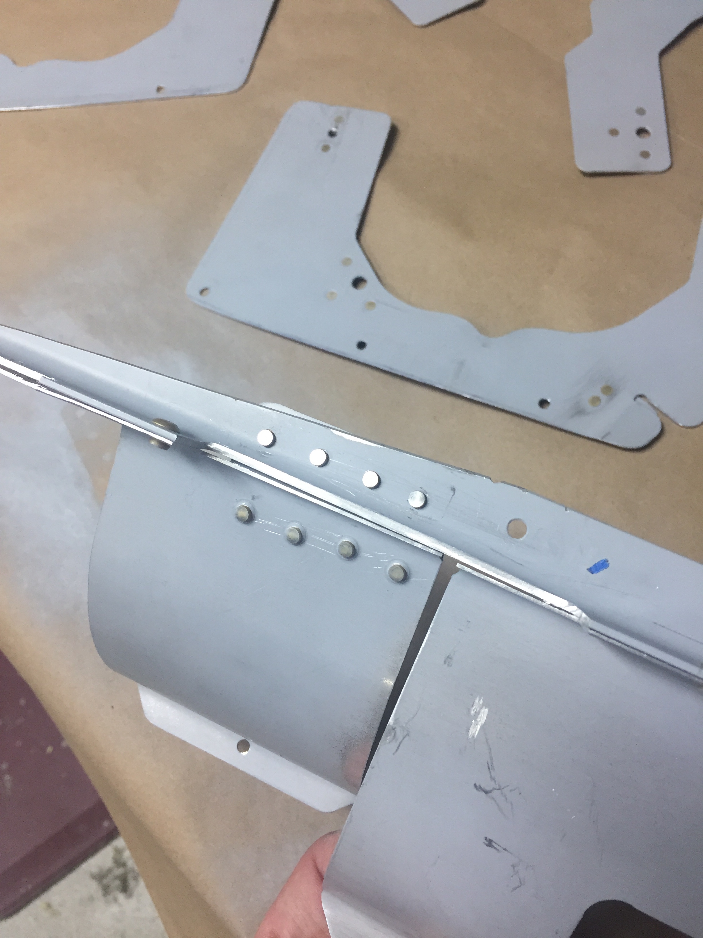
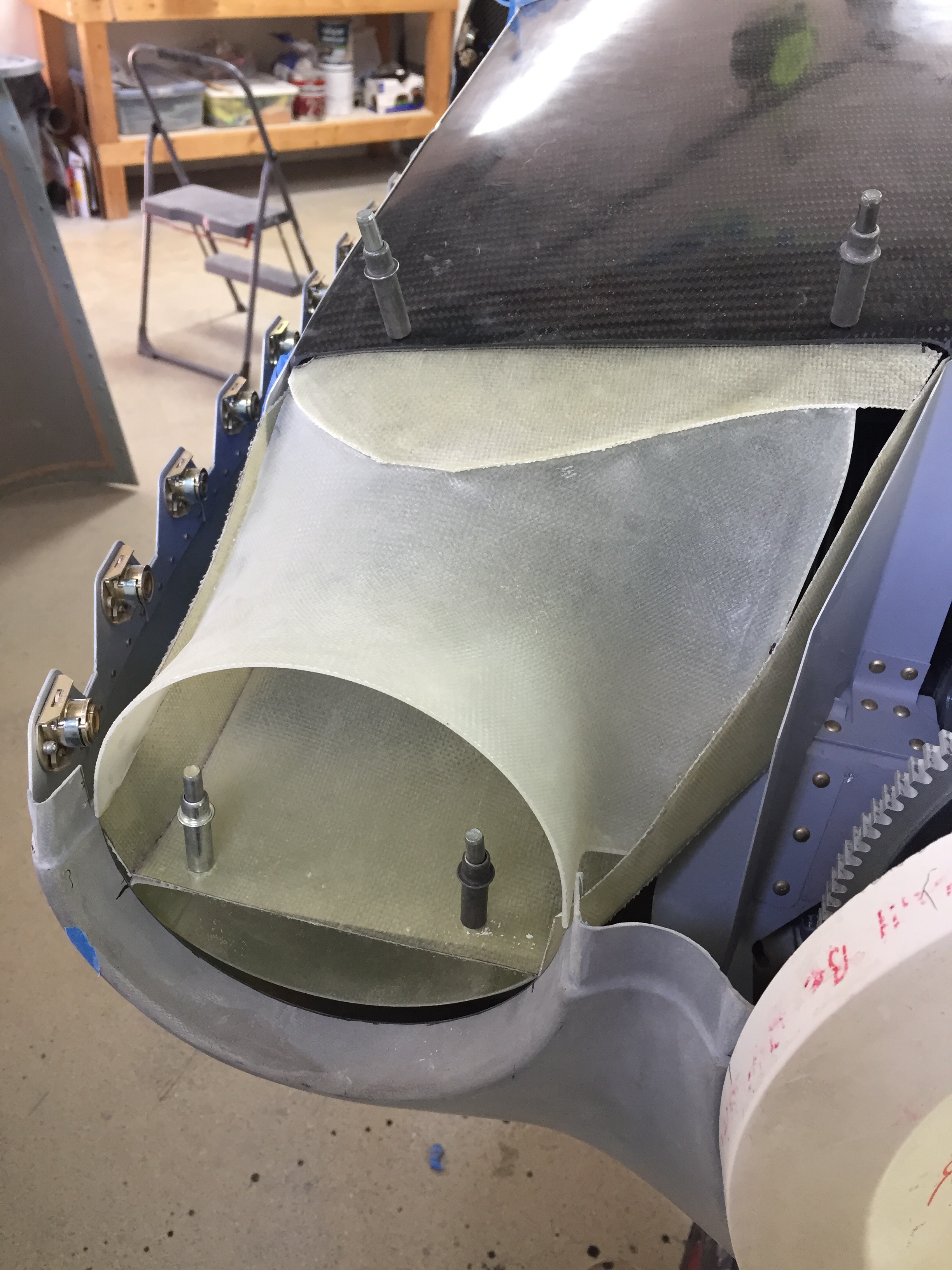
The upper ramps from Show Planes are the same size as the openings, so I started with those as a transition to the plenum. Part of the kit is some thin flatstock fiberglass that I wound up using to create the cooling ducts. I used some manilla folders to create templates and basically pieced it all together using the fiberglass and super glue. Starting on the right side was simple, as there is no modifications needed and it’s a much simpler routing for air to enter the plenum covered area.
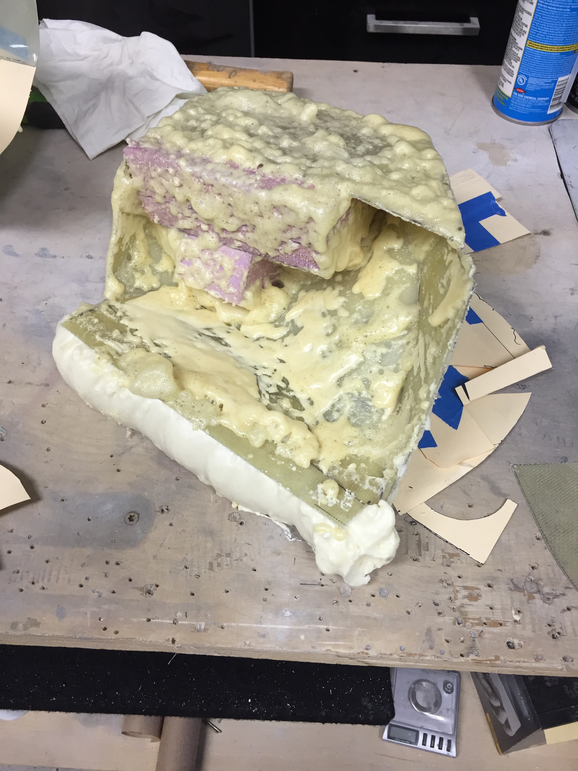
Again, I figured I’d use this rough build up as a mold to create a sleek curvy, sexy, duct that would look like it came from a Formula 1 team. So I got a brilliant idea of filling it with blocks of foam and then using spray foam out of a can to fill in the gaps. I’d then sand, trim, and shape before using it as a mold. Well guess how that worked? Not great, folks. Not great. I didn’t realize that spray foam has to be exposed to air to set up. So me putting the duct in a plastic bag in a box resulted not in a nice firm square, but a grocery bag full of gooy sticky snot.
I then decided I’m making it difficult and should just keep it simple, stupid. So I decided to stick with the original prototypes and just reinforce the joints and smoth as much as possible. While I waited for the disaster to finish curing so I could clean all the foam back off, I started on the left duct. This was much more complicated with the compressor in the way. Not only do I need to get around the compressor, but also the tensioning arm and v-belt. Finally, the prop governor is there too and oh, wait, I forgot, the refrigerant line from the compressor. Again, I used manilla folders cut up as templates and just pieced it all together, maximizing the amount of space and using the upper ramp from Show Planes as the starting point.
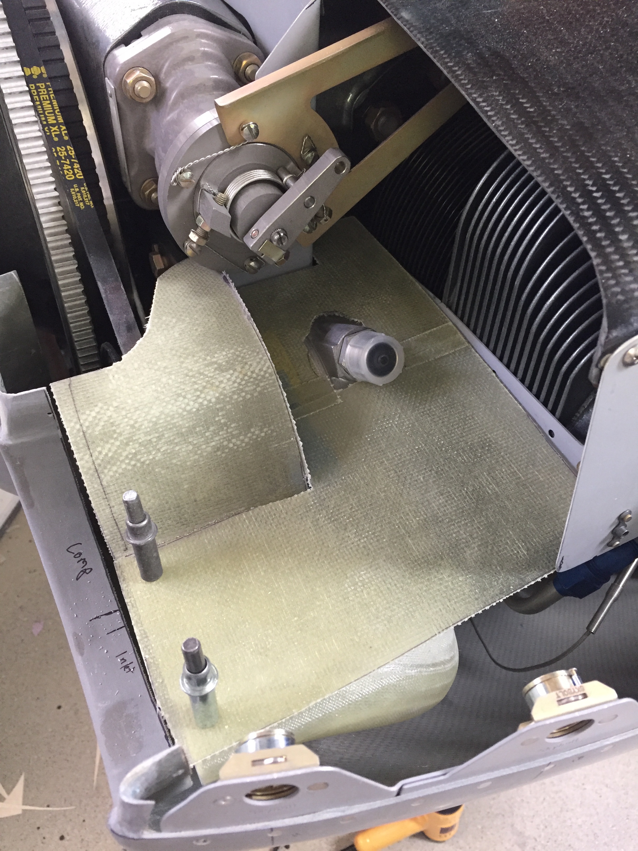
The end result is not too shabby, even if it’s not beautiful. I hope it’s functional. I finished cleaning the foam and set about reinforcing all of the joints with glass tape left over from tip fairings. Once cured, I did a final fit and trim to provide about 3/8″ clearance from the cowl openings and evened them up with the induction ducts below. This clearance allows the engine to vibrate and twist a bit within the cowl without cracking the ducts, as you don’t want the two rigidly attached to each other. I really debated on how to close that gap, thinking about creating flexible ducts from the start or taking what I have at this point and using a rubber strip to seal it. In the end, I copied an idea from the DA-40 I fly and ordered some bulb seal from McMaster Carr. I’m hoping this will keep the air from leaking around the duct but allow the engine to move within the cowling. Again, some testing during first few flights will tell.
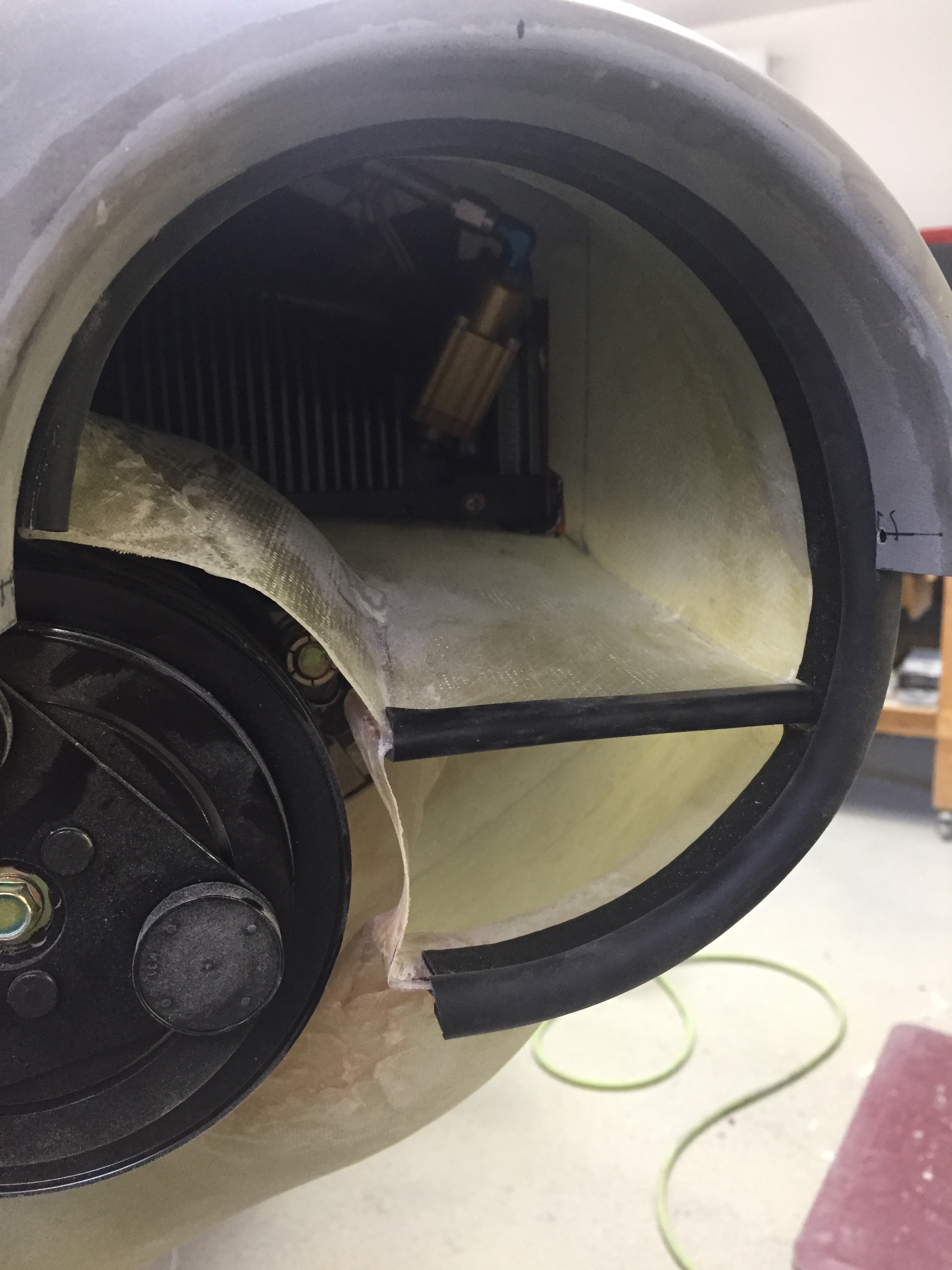
I may go back and cosmetically clean these ducts up before paint just to make them look good, but for now, I shot a coat of black paint on them to mask imperfections. I still need to fabricate up a small ramp that will cover the exposed face of the compressor and help direct smooth air into the ducts. If I find high temps on 1 3 5 clyinders during flight tests, I’ll copy Gaylon and pull the left induction intake to open that entire side to cooling. I’ll be honest, this has really weighed on my mind how to create these ducts. I’m sure there’s a better or fancier way of doing them, but for me, this is a good start. If they work that’s great and if not, I at least have a good starting point. These were the last items needed before cleaning the engine off and sealing the baffles using 3M firestop.
